US3451663A - Heating device for aircraft engines - Google Patents
Heating device for aircraft engines Download PDFInfo
- Publication number
- US3451663A US3451663A US713225A US3451663DA US3451663A US 3451663 A US3451663 A US 3451663A US 713225 A US713225 A US 713225A US 3451663D A US3451663D A US 3451663DA US 3451663 A US3451663 A US 3451663A
- Authority
- US
- United States
- Prior art keywords
- housing
- heating device
- heating
- heater unit
- air
- Prior art date
- Legal status (The legal status is an assumption and is not a legal conclusion. Google has not performed a legal analysis and makes no representation as to the accuracy of the status listed.)
- Expired - Lifetime
Links
- 238000010438 heat treatment Methods 0.000 title description 40
- 239000000446 fuel Substances 0.000 description 14
- 238000010276 construction Methods 0.000 description 8
- 238000005192 partition Methods 0.000 description 7
- 239000007788 liquid Substances 0.000 description 5
- 239000000945 filler Substances 0.000 description 2
- 239000000463 material Substances 0.000 description 2
- 239000004020 conductor Substances 0.000 description 1
- 239000000203 mixture Substances 0.000 description 1
- 238000007789 sealing Methods 0.000 description 1
Images
Classifications
-
- B—PERFORMING OPERATIONS; TRANSPORTING
- B64—AIRCRAFT; AVIATION; COSMONAUTICS
- B64F—GROUND OR AIRCRAFT-CARRIER-DECK INSTALLATIONS SPECIALLY ADAPTED FOR USE IN CONNECTION WITH AIRCRAFT; DESIGNING, MANUFACTURING, ASSEMBLING, CLEANING, MAINTAINING OR REPAIRING AIRCRAFT, NOT OTHERWISE PROVIDED FOR; HANDLING, TRANSPORTING, TESTING OR INSPECTING AIRCRAFT COMPONENTS, NOT OTHERWISE PROVIDED FOR
- B64F5/00—Designing, manufacturing, assembling, cleaning, maintaining or repairing aircraft, not otherwise provided for; Handling, transporting, testing or inspecting aircraft components, not otherwise provided for
- B64F5/20—Ground installations for de-icing aircraft
- B64F5/27—Ground installations for de-icing aircraft by irradiation, e.g. of infrared radiation
Definitions
- a portable heating device for heating aircraft engines comprising a heater unit including a vhousing and having af'burner mechanism therein connected to a source of fuel.
- a plenum housing positioned upon the heater unit and having a transverse horizontal partition therein to define the interior of lthe plenum housing into an upper and lower chamber through which air to b'e yheated passes.
- the heating device 10 is comprised of a'heater unit ⁇ 11.
- This heater unit 11 may be a conventional camp type stove which is commercially available, such las the Coleman Model Two-Burner Standard Camp Stove.
- the heater unit is comprised of a housing 12, including a front wall 13, a rear wall 14, end walls 15 and a bottom wall 16.
- the interior of the housing 12 defines a burner chamber and a pair of burners 117 are positioned therein.
- the housing is completely open at its upper end and is provided with a grill 18, which is hingedly connected tothe rear wall 14 by suitable hingesleeves 19.
- the grill 18 is swingable about anaxis vdened, by the hinge sleeve 19 to permit access tothe interior of the housing.
- the heater unit 1'1 is provided with a fuel receptacle o r'tank 20 which is adapted to contain a predetermined amount of liquid fuel therein.
- the tank 20 has ay filler opening closed by suitable filler cap 21 and is also promechanism 23 is connected to the opening to permit the flow of fuel and Iair through and into a conduit 24 which is connected in communicating relation to a device 25 for admixing the liquid fuel in proper ratio with air.
- the fuel-mixing device 25 is also connected by suitable unle s the en ine is rst heated. However even thou h s g g be intercommunicated selectively w1th the tank 20.
- the present invention is directed to the provision of the rather compact portable heating devicel for use in heating aircraft engines.
- the heating device comprises a relatively small heater unit including a housing having a burner unit therein which is adapted to utilize liquid fuel.
- the heating ldevice alsoin'cludes a plenumhousing which is detachably mounted upon thev heating unit and whose heating chambers are, arrangedk and constructed so that the incoming air is preheated thereby permitting a very eiiicient heat exchange actionto take place.
- the plenum housing is also arranged and constructed whereby the interior thereof is completely sealed lfrom, the burner unit so that the air passing therethrough which is heated, -and which is then directed 'through a conduit by means of a blower mechanism Vinto the aircraft engine carries no volatile materials.
- The' present heater device because of its compact construction, may be readily carried from one place toanother and may be readily operated so that it is ideall for owners of small aircraft..
- valve mechanism 23 is provided with a suitable control knob 26 for controlling movement of the valve element of the valve mechanism so that the conduit 22 may needle valve 27 is also provided to permit very accurate controlling of ow of fuel through the conduit 24.
- the heating unit 11, heretofore described, does not, per se, constitute the present invention. This heating unit as pointed out above is of conventional construction and is commercially available. In this regard, it is pointed out that the tank 20 may be disconnected from the conduit 24 and maybe inserted into the interior of the housing 12 when the unit is not in use. However, the burner unit does form a part of the heating device which constitutes the present invention.
- the heating device 10 includes an air heating unit 28 which is comprised of a plenum housing 29.
- the plenum housing 29 is comprised of an upper wall 30, a lower i wall 31, end walls 32 and side walls 33.
- a horizontally having outturned end flanges 38 is rigidly secured to the -upper wall 30 andthe'partition 34 to define a passage interconnecting the lower chamber 36 with the outlet 39 formed inthe upperwall 30.
- v z. r f One of the end walls 32 has an elongate slot 40 formed -1- therein which extends throughout substantially the entire exploded perspective view of the inven- 1"3 length of the end vwall to dene an inlet opening therein.
- A'wall element 41 is rigidly atlxed to the partition 34 and to lthe lower wall 31 and is spaced inwardly from the end wall 32 in which the opening 40 is formed.
- the lower chamber 36 is closed with respect to the inlet 40 and a vertical passage is defined which communicates with the upper chamber 35.
- the partition 34 has one edge thereof spaced inwardly from one of the endvwalls 32 substantially the width of the partition ⁇ 34 so that an elongate opening 42 is delined to intercommunicate the chambers 35 and 36 remote from the inlet 40.
- the means for causing the air to flow through the housing 28 comprises a blower 43 which is comprised of housing 44 secured to the upper wall 3l) of the plenum,A housing 29 by brackets 44a.
- the blower 43 has a fan therein which is driven by suitable six volt or twelve volt electric motor 45.
- the inlet or intake sleeve 46 of the fan is connected in communicating relation to the outlet 39 in the plenum housing 29.
- the outlet of the fan is detachably connected to one end of an elongate iiexible hose or conduit 47 and the other end of the hose is adapted to be positioned into the engine compartment of a conventional aircraft A.
- the heater unit housing 12 is hingedly connected to the plenum housing 28 by suitable hinge member 48 which are of well-known construction.
- the hinge elements 48 are secured to adjacent side walls of the heater unit housing and plenum housing respectively.
- the heater unit housing 11 is also provided with a pair of latch members 49 while the plenum housing 29 is provided with latch members 50. It will be noted that these latch members 49 and 50 are secured to adjacent side walls of the plenum housing and heater unit housing and actually constitute conventional trunk latches of wellknown construction.
- the plenum housing 29 is also provided with a carrying handle 51 and the heater unit housing may also be provided with a carrier handle if desired.
- the heater unit housing may also be provided with suitable legs 52, one leg structure located adjacent each end and each being swingable between an operative and inoperative position. It is further pointed out that since the heater unit 11 is provided with two burners, a suitable valve device 53 may be provided to permit one of the burners to be closed and rendered inoperative while the other burneris being used.
- an operator will release the latch members 49 from the latch members 50 to allow swinging movement of the air heating unit 28 away from the heater unit housing to permit access to the interior of the latter.
- the tank 20 will be removed therefrom and will be connected to the fuel mixing device 25 by conduit 24 in a well known manner.
- the burners may be then ignited, or in the event that only one burner is to be used, the other burner may be shut olf.
- the air heating unit 28 may then be swung to the closed position to rest upon the grill 18. This ⁇ arrangement permits vertical spacing of the lower wall of the air heating unit above the upper marginal edges of the heater unit housing 12 so that air may readily ow into the heater unit housing.
- a switch 54 for the electric motor 45 will be closed so that the motor is energized.
- the electric motor 45 will be connected by suitable electrical conductors 55 to a source of electrical current, such as the electric power system for the aircraft A.
- the fan of the blower will be revolved and will cause the air to ow through the inlet 40 and transversely through the upper chamber 35.
- the air will then flow downwardly through the opening 42 and circulate through the lower chamber 36 of the air heating unit. Thereafter, the air will flow upwardly through the outlet 39 into the fan housing 44, then through the iiexible conduit 47, and finally into the engine compartment.
- the air By causing the air to circulate through the upper chamber 34 prior to iiowing through the lower chamber, it will be seen that the air is irst preheated by the warmer air flowing through the lower chamber 36.
- a highly etiicient heat exchange action takes place in the uniquely chambered plenum housing 29.
- the present heating device permits the use of a liquid fuel, such as gasoline mixtures used in camping stove equipment. Liquid fuel is much easier to handle and utilize in heating devices than commercial gaseous fuels.
- the apparatus very quickly and etliciently heat an engine compartment with a minimum of effort by user, but there is little, if any, danger that the aircraft or user will be injured through the use of the heating device.
- the tank 20 may be again placed interiorly of the housing 12, the flexible conduit 24 disconnected from the aircraft and from the heating device and the entire apparatus releasably locked in its inoperative transport condition.
- the entire heating device is of relatively small compass and may be easily carried from place to place.
- a portable heating device for heating aircraft engines comprising a heater unit including a housing having an interior and defining a burner chamber, a burner mechanism positioned in said burner chamber,
- a small compact fuel receptacle adapted to contain fuel therein and connected in communicating relation with said burner mechanism
- a plenum housing positioned upon said heater unit housing and including a lower wall and an intermediate transverse horizontal partition whereby the interior of said plenum housing comprises an upper chamber and a lower chamber intercommunicated with each other adjacent one side of said housing,
- blower mechanism on said plenum housing having an inlet intercommunicated with the outlet in said plenum housing, said blower mechanism having an outlet,
- an elongate conduit having one end connected with said outlet of the blower mechanism and having the other end thereof adapted for connection with an aircraft engine for heating the same.
- plenum housing is of generally rectangular configuration and in addition to said lower wall includes an upper wall, side walls and end walls.
- said inlet opening in said plenum housing comprises an elongate opening corresponding in length to substantially the length of one of said end walls of said plenum housing.
Landscapes
- Engineering & Computer Science (AREA)
- Health & Medical Sciences (AREA)
- General Health & Medical Sciences (AREA)
- Toxicology (AREA)
- Manufacturing & Machinery (AREA)
- Transportation (AREA)
- Aviation & Aerospace Engineering (AREA)
- Air-Conditioning For Vehicles (AREA)
Description
June 24, 1969 p 1,VH|| E 3,451,663
HEATING DEVICE FOR AIRCRAFT ENGINES Filed March I4, 1968 llll United States Patent O 3,451,663 HEATING DEVICE FOR AIRCRAFT ENGINES Peter J. Hille, 416 E. 2nd St., Willmar, Minn. 56201 Filed Mar. 14, 1968, Ser.'No. 713,225`` Int. Cl. F23l'15/00 U.S. Cl. 263-19 i ABSTRACT OF THE DISCLOSURE A portable heating device for heating aircraft engines comprising a heater unit including a vhousing and having af'burner mechanism therein connected to a source of fuel. A plenum housing positioned upon the heater unit and having a transverse horizontal partition therein to define the interior of lthe plenum housing into an upper and lower chamber through which air to b'e yheated passes.
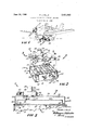
vSummary of theinvention Quite often when `aircraft .engines are subjected @to extremely cold weather, it is diicult to .start .the engine Y i Claims ICC ` Detailed description of the invention erally bythe reference numeral 10, is thereshown. The heating device 10 is comprised of a'heater unit`11. This heater unit 11 may be a conventional camp type stove which is commercially available, such las the Coleman Model Two-Burner Standard Camp Stove. The heater unit is comprised of a housing 12, including a front wall 13, a rear wall 14, end walls 15 and a bottom wall 16. The interior of the housing 12 defines a burner chamber and a pair of burners 117 are positioned therein. It will be noted that the housing is completely open at its upper end and is provided with a grill 18, which is hingedly connected tothe rear wall 14 by suitable hingesleeves 19. Thus the grill 18 is swingable about anaxis vdened, by the hinge sleeve 19 to permit access tothe interior of the housing. v
"The heater unit 1'1 is provided with a fuel receptacle o r'tank 20 which is adapted to contain a predetermined amount of liquid fuel therein. The tank 20 has ay filler opening closed by suitable filler cap 21 and is also promechanism 23 is connected to the opening to permit the flow of fuel and Iair through and into a conduit 24 which is connected in communicating relation to a device 25 for admixing the liquid fuel in proper ratio with air.
The fuel-mixing device 25 is also connected by suitable unle s the en ine is rst heated. However even thou h s g g be intercommunicated selectively w1th the tank 20. A
there vare currently. available some vheating devices for heating aircraft engines, many of these devicesare quite large and difiicultn to handle as |well .as being expensive. Other of these heating devicesbecause y of their particular construction, present certain hazardvsrlduring operation thereof. l Y Y.
The present invention .is directed to the provision of the rather compact portable heating devicel for use in heating aircraft engines. The heating device comprises a relatively small heater unit including a housing having a burner unit therein which is adapted to utilize liquid fuel. The heating ldevice .alsoin'cludes a plenumhousing which is detachably mounted upon thev heating unit and whose heating chambers are, arrangedk and constructed so that the incoming air is preheated thereby permitting a very eiiicient heat exchange actionto take place. The plenum housing is also arranged and constructed whereby the interior thereof is completely sealed lfrom, the burner unit so that the air passing therethrough which is heated, -and which is then directed 'through a conduit by means of a blower mechanism Vinto the aircraft engine carries no volatile materials. The' present heater device, because of its compact construction, may be readily carried from one place toanother and may be readily operated so that it is ideall for owners of small aircraft..
Y `Brief description of the figures ofthe drawingy i ing in the direction of the arrows.
conduits to the burners 17 so that when the valve mechanism 23 is open, fuel will ow to the respective burners. Valve mechanism 23 is provided with a suitable control knob 26 for controlling movement of the valve element of the valve mechanism so that the conduit 22 may needle valve 27 is also provided to permit very accurate controlling of ow of fuel through the conduit 24. The heating unit 11, heretofore described, does not, per se, constitute the present invention. This heating unit as pointed out above is of conventional construction and is commercially available. In this regard, it is pointed out that the tank 20 may be disconnected from the conduit 24 and maybe inserted into the interior of the housing 12 when the unit is not in use. However, the burner unit does form a part of the heating device which constitutes the present invention. 1 fThe heating device 10 includes an air heating unit 28 which is comprised of a plenum housing 29. The plenum housing 29 is comprised of an upper wall 30, a lower i wall 31, end walls 32 and side walls 33. A horizontally having outturned end flanges 38 is rigidly secured to the -upper wall 30 andthe'partition 34 to define a passage interconnecting the lower chamber 36 with the outlet 39 formed inthe upperwall 30. v z. r f One of the end walls 32 has an elongate slot 40 formed -1- therein which extends throughout substantially the entire exploded perspective view of the inven- 1"3 length of the end vwall to dene an inlet opening therein. A'wall element 41 is rigidly atlxed to the partition 34 and to lthe lower wall 31 and is spaced inwardly from the end wall 32 in which the opening 40 is formed. Thus the lower chamber 36 is closed with respect to the inlet 40 and a vertical passage is defined which communicates with the upper chamber 35. In the Vembodiment shown, the partition 34 has one edge thereof spaced inwardly from one of the endvwalls 32 substantially the width of the partition `34 so that an elongate opening 42 is delined to intercommunicate the chambers 35 and 36 remote from the inlet 40. With this arrangement, it will be seen that air passes through the upper chamber 35 and then passes through the lower chamber 36 before it is discharged through the outlet 39.
The means for causing the air to flow through the housing 28 comprises a blower 43 which is comprised of housing 44 secured to the upper wall 3l) of the plenum,A housing 29 by brackets 44a. The blower 43 has a fan therein which is driven by suitable six volt or twelve volt electric motor 45. The inlet or intake sleeve 46 of the fan is connected in communicating relation to the outlet 39 in the plenum housing 29. The outlet of the fan is detachably connected to one end of an elongate iiexible hose or conduit 47 and the other end of the hose is adapted to be positioned into the engine compartment of a conventional aircraft A.
In the embodiment shown, the heater unit housing 12 is hingedly connected to the plenum housing 28 by suitable hinge member 48 which are of well-known construction. The hinge elements 48 are secured to adjacent side walls of the heater unit housing and plenum housing respectively. The heater unit housing 11 is also provided with a pair of latch members 49 while the plenum housing 29 is provided with latch members 50. It will be noted that these latch members 49 and 50 are secured to adjacent side walls of the plenum housing and heater unit housing and actually constitute conventional trunk latches of wellknown construction. The plenum housing 29 is also provided with a carrying handle 51 and the heater unit housing may also be provided with a carrier handle if desired. The heater unit housing may also be provided with suitable legs 52, one leg structure located adjacent each end and each being swingable between an operative and inoperative position. It is further pointed out that since the heater unit 11 is provided with two burners, a suitable valve device 53 may be provided to permit one of the burners to be closed and rendered inoperative while the other burneris being used.
In use, an operator will release the latch members 49 from the latch members 50 to allow swinging movement of the air heating unit 28 away from the heater unit housing to permit access to the interior of the latter. The tank 20 will be removed therefrom and will be connected to the fuel mixing device 25 by conduit 24 in a well known manner. The burners may be then ignited, or in the event that only one burner is to be used, the other burner may be shut olf. The air heating unit 28 may then be swung to the closed position to rest upon the grill 18. This `arrangement permits vertical spacing of the lower wall of the air heating unit above the upper marginal edges of the heater unit housing 12 so that air may readily ow into the heater unit housing. A switch 54 for the electric motor 45 will be closed so that the motor is energized. In this regard, it is pointed out that the electric motor 45 will be connected by suitable electrical conductors 55 to a source of electrical current, such as the electric power system for the aircraft A.
The fan of the blower will be revolved and will cause the air to ow through the inlet 40 and transversely through the upper chamber 35. The air will then flow downwardly through the opening 42 and circulate through the lower chamber 36 of the air heating unit. Thereafter, the air will flow upwardly through the outlet 39 into the fan housing 44, then through the iiexible conduit 47, and finally into the engine compartment. By causing the air to circulate through the upper chamber 34 prior to iiowing through the lower chamber, it will be seen that the air is irst preheated by the warmer air flowing through the lower chamber 36. Thus a highly etiicient heat exchange action takes place in the uniquely chambered plenum housing 29.
By sealing the lower chamber 36 from the interior of the heater unit housing, only heated air liows through the air heating unit and into the conduit 47 for heating the aircraft engine. Thus, there is absolutely no danger that any volatile material will be discharged into the aircraft engine compartment. Further, the present heating device permits the use of a liquid fuel, such as gasoline mixtures used in camping stove equipment. Liquid fuel is much easier to handle and utilize in heating devices than commercial gaseous fuels.
Not only will the apparatus very quickly and etliciently heat an engine compartment with a minimum of effort by user, but there is little, if any, danger that the aircraft or user will be injured through the use of the heating device. After the engine compartment is heated sufficiently, the tank 20 may be again placed interiorly of the housing 12, the flexible conduit 24 disconnected from the aircraft and from the heating device and the entire apparatus releasably locked in its inoperative transport condition. When in this condition, the entire heating device is of relatively small compass and may be easily carried from place to place.
From the foregoing description, it will be seen that I have provided a novel aircraft heating device which may be utilized to very quickly and efficiently heat an aircraft engine by an operator with a minimum of effort. Because of its compact construction, the device may be readily carried from place to place and may be used to heat substantially any conventional aircraft engine.
Thus it will be seen that I have provided a novel heating device for aircraft engines which is not only of simple and inexpensive construction, but one which functions in a more eiiicient manner than any heretofore known comparable device.
It will, of course, be understood that various changes may be made in the form, details, arrangement and proportions of the various parts without departing from the scope of my invention.
What I claim is:
1. A portable heating device for heating aircraft engines comprising a heater unit including a housing having an interior and defining a burner chamber, a burner mechanism positioned in said burner chamber,
a small compact fuel receptacle adapted to contain fuel therein and connected in communicating relation with said burner mechanism,
a plenum housing positioned upon said heater unit housing and including a lower wall and an intermediate transverse horizontal partition whereby the interior of said plenum housing comprises an upper chamber and a lower chamber intercommunicated with each other adjacent one side of said housing,
an inlet opening in said plenum housing communicating with said upper chamber, an outlet in said plenum housing communicating with said lower chamber,
a blower mechanism on said plenum housing having an inlet intercommunicated with the outlet in said plenum housing, said blower mechanism having an outlet,
an elongate conduit having one end connected with said outlet of the blower mechanism and having the other end thereof adapted for connection with an aircraft engine for heating the same.
2. The heating device as deiined in claim 1 and means releasably locking said plenum housing to said heater unit housing.
3. The heating device as defined in claim 1 wherein said plenum housing is of generally rectangular configuration and in addition to said lower wall includes an upper wall, side walls and end walls.
4. The heating device as defined in claim 3 wherein said outlet in said plenum housing extends vertically through the partition in said upper wall, and wherein said blower mechanism is mounted on the upper wall of said plenum housing.
5. The heating device as defined in claim 1 wherein said bottom wall of said plenum housing is of substantially imperforate construction to seal said lower chamber of the plenum housing from the burner chamber of said heater unit.
6. The heating device as defined in claim 3 wherein said inlet opening in said plenum housing comprises an elongate opening corresponding in length to substantially the length of one of said end walls of said plenum housing.
6 References Cited UNITED STATES PATENTS 6/1932 Gilly 2-63-19 9/1942 King 263-19
Applications Claiming Priority (1)
| Application Number | Priority Date | Filing Date | Title |
|---|---|---|---|
| US71322568A | 1968-03-14 | 1968-03-14 |
Publications (1)
| Publication Number | Publication Date |
|---|---|
| US3451663A true US3451663A (en) | 1969-06-24 |
Family
ID=24865296
Family Applications (1)
| Application Number | Title | Priority Date | Filing Date |
|---|---|---|---|
| US713225A Expired - Lifetime US3451663A (en) | 1968-03-14 | 1968-03-14 | Heating device for aircraft engines |
Country Status (1)
| Country | Link |
|---|---|
| US (1) | US3451663A (en) |
Cited By (6)
| Publication number | Priority date | Publication date | Assignee | Title |
|---|---|---|---|---|
| US3809527A (en) * | 1973-04-16 | 1974-05-07 | R Newman | Portable heater for an automobile |
| US4445469A (en) * | 1982-04-05 | 1984-05-01 | Louis Suhayda | Engine heater |
| US5121739A (en) * | 1990-07-23 | 1992-06-16 | Barker Stanley G | Portable heat dispensing unit |
| US6941677B2 (en) | 2001-08-10 | 2005-09-13 | Taps, Llc | Portable air heating system |
| US20070267536A1 (en) * | 2005-05-27 | 2007-11-22 | Hill Herbert A | Method and apparatus for pre-heating an aircraft engine |
| US7997004B1 (en) | 2001-08-10 | 2011-08-16 | Taps, Llc | Portable air heating system |
Citations (2)
| Publication number | Priority date | Publication date | Assignee | Title |
|---|---|---|---|---|
| US1862114A (en) * | 1930-07-07 | 1932-06-07 | Charles G Gilly | Airplane engine heater |
| US2295177A (en) * | 1940-07-29 | 1942-09-08 | Leo M Harvey | Preheater for aircraft |
-
1968
- 1968-03-14 US US713225A patent/US3451663A/en not_active Expired - Lifetime
Patent Citations (2)
| Publication number | Priority date | Publication date | Assignee | Title |
|---|---|---|---|---|
| US1862114A (en) * | 1930-07-07 | 1932-06-07 | Charles G Gilly | Airplane engine heater |
| US2295177A (en) * | 1940-07-29 | 1942-09-08 | Leo M Harvey | Preheater for aircraft |
Cited By (7)
| Publication number | Priority date | Publication date | Assignee | Title |
|---|---|---|---|---|
| US3809527A (en) * | 1973-04-16 | 1974-05-07 | R Newman | Portable heater for an automobile |
| US4445469A (en) * | 1982-04-05 | 1984-05-01 | Louis Suhayda | Engine heater |
| US5121739A (en) * | 1990-07-23 | 1992-06-16 | Barker Stanley G | Portable heat dispensing unit |
| US6941677B2 (en) | 2001-08-10 | 2005-09-13 | Taps, Llc | Portable air heating system |
| US7997004B1 (en) | 2001-08-10 | 2011-08-16 | Taps, Llc | Portable air heating system |
| US8819957B1 (en) | 2001-08-10 | 2014-09-02 | Taps, Llc | Portable air heating system |
| US20070267536A1 (en) * | 2005-05-27 | 2007-11-22 | Hill Herbert A | Method and apparatus for pre-heating an aircraft engine |
Similar Documents
| Publication | Publication Date | Title |
|---|---|---|
| US3451663A (en) | Heating device for aircraft engines | |
| US3768458A (en) | Instant water heater | |
| US2285725A (en) | Air conditioner | |
| US3383778A (en) | Mobile hair dryer | |
| US2026929A (en) | Heater and ventilator for motor vehicles | |
| US2055577A (en) | Pneumatic vacuum cleaner | |
| US2015982A (en) | Portable electric prewarmer for airship engines | |
| US3192916A (en) | Portable hot water heater | |
| US4108143A (en) | Forced air heater blower | |
| GB884918A (en) | Improvements in or relating to combined heating and cooling apparatus for vehicles | |
| US3076604A (en) | Control system for air heater | |
| US2188388A (en) | Automobile heater and defroster | |
| GB1109649A (en) | Heat storage apparatus | |
| US3666174A (en) | Blower apparatus for air-supported structures | |
| US1150619A (en) | Kerosene-carbureter. | |
| US3582496A (en) | Thermal fogger | |
| US2237452A (en) | Heating and ventilating apparatus for automobiles | |
| US1936875A (en) | Ventilating and heating apparatus | |
| US1226849A (en) | Electric water-heater. | |
| US4392609A (en) | Portable preheating system for internal combustion engines | |
| US3272966A (en) | Device for drying hair and fingernails | |
| US2077545A (en) | Sewage sludge treatment plant | |
| US2038773A (en) | Humidifier | |
| GB363370A (en) | Improvements in and relating to means for heating, cooling, and ventilating enclosures | |
| US2858823A (en) | Liquid heating device for warming engines and the like |