US3441272A - Adjustable stilts - Google Patents
Adjustable stilts Download PDFInfo
- Publication number
- US3441272A US3441272A US622013A US3441272DA US3441272A US 3441272 A US3441272 A US 3441272A US 622013 A US622013 A US 622013A US 3441272D A US3441272D A US 3441272DA US 3441272 A US3441272 A US 3441272A
- Authority
- US
- United States
- Prior art keywords
- stilt
- lock
- foot mount
- foot
- release pin
- Prior art date
- Legal status (The legal status is an assumption and is not a legal conclusion. Google has not performed a legal analysis and makes no representation as to the accuracy of the status listed.)
- Expired - Lifetime
Links
- 241000272165 Charadriidae Species 0.000 title description 79
- 238000010276 construction Methods 0.000 description 4
- 210000003813 thumb Anatomy 0.000 description 4
- 230000006835 compression Effects 0.000 description 2
- 238000007906 compression Methods 0.000 description 2
- 230000000994 depressogenic effect Effects 0.000 description 2
- 238000000034 method Methods 0.000 description 2
- 239000011435 rock Substances 0.000 description 2
- 102100028029 SCL-interrupting locus protein Human genes 0.000 description 1
- 210000004247 hand Anatomy 0.000 description 1
- 238000003780 insertion Methods 0.000 description 1
- 230000037431 insertion Effects 0.000 description 1
- 238000004519 manufacturing process Methods 0.000 description 1
- 239000000463 material Substances 0.000 description 1
- 239000012858 resilient material Substances 0.000 description 1
Images
Classifications
-
- A—HUMAN NECESSITIES
- A63—SPORTS; GAMES; AMUSEMENTS
- A63B—APPARATUS FOR PHYSICAL TRAINING, GYMNASTICS, SWIMMING, CLIMBING, OR FENCING; BALL GAMES; TRAINING EQUIPMENT
- A63B25/00—Stilts or the like
Definitions
- An object of this invention is to provide an inner support stilt member enhoused by an outer vertically moveable stilt member to which is hinged; a biased, horizontally arcuated foot mount carrying a stilt lock and release mechanism to assure for positive locking engagement with the inner support stilt member.
- Still another object of the present invention is to provide for manual adjustment of the foot mount biasing mechanism so as to bias the foot mount either inwardly against the outer stilt support member with the locking mechanism engaging the inner stilt support member forming a rigid stilt or biasing the foot mount outwardly from the outer stilt member extracting the lock and release mechanism from the inner support stilt member and thus freeing the outer stilt member to move vertically on the inner stilt member.
- Another object of this invention is to provide for a stilt which is locked, forming a rigid stilt which the user, in use, unlocks for vertical movement; or the same stilt which is unlocked for vertical movement and the user, in use, locks to form a'rigid stilt.
- a further object of the present invention is to provide the inner support stilt member with vertically disposed through holes in one wall where by a portion of the wall immediately above and including material forming the upper portion of the hole is depressed to form a vertically extending incline terminating at the lower end thereof in the upper portion of the hole. This portion of the hole is recessed somewhat below the lower portion of the hole, thus forming a ledge like abutment to encounter the stilt lock and release mechanism.
- Still another object of the invention is to provide for a pair of stilts which are interchangeable, with all parts performing the same function interchangeable between the stilts; thus simplifying manufacture.
- FIGURE 1 is a side elevation view of an adjustable stilt made in accordance with the present invention with the foot mount biased inwardly.
- FIGURE 2 is a side elevation, partly broken away, with the foot mount biased outwardly.
- FIGURE 3 is a cross sectional view taken along line 33 of FIGURE 2, showing the interior of the foot mount.
- numeral 1 indicates the outer stilt member which may be round, rectangular or of any suitable cross section.
- the inner support stilt member 2 Vertically moveable within the outer stilt member 1 is the inner support stilt member 2.
- the inner stilt member is provided with a cup 3; the inner vertical walls of which frictionally engage the lower, outer walls of the inner member 2.
- the upper walls of this cup extend above the surface engaging resilient material of the shoe 19 so as to abut the lower end of the outer member and terminate the vertical movement of the inner member into the outer member.
- a U shaped shim 17 is attached to the lower inner portion of the outer stilt member with the open end of the U facing the foot mount 5.
- U shaped shims 18 and 1811 are attached to the upper end of the inner stilt member and are oriented as is shim 17. The outward vertical movement of the inner stilt member is terminated by shim 18 abutting shim 17. Shims 18 and 18a are so spaced apart so as to maintain strength and stability of the stilt upon terminated outward vertical movement of the inner stilt member.
- the inner stilt member is provided with a plurality of vertically spaced apart through holes 4 which receive stilt lock and release pin 10, an integral component of foot mount 5. It will be noted holes 4 extend from above cup 3 to just below the U shaped shim 18 so as to provide that the inner stilt member may be locked at any desired height by the user. It also will be noted the portion immediately above and including the upper half arc of holes 4 is recessed inwardly to provide for positive locking and eliminate slippage of lock pin 10 as it engages hole 4.
- Lock and release pin 10 is axially aligned, spring loaded and pivotally adjustable within the foot mount 5.
- Spring loading of the lock and release pin is accomplished by compression spring 12 exerting inward pressure against shoulder 13 of the lock pin.
- the horizontal movement of lock and release pin 10 may be terminated by the lock and release pin not aligning with hole 4; but, instead, abutting the face area of the inner stilt member between holes 4.
- the lock and release pin has stopped and the foot mount arcs on inwardly until it is terminated by abutting the outer stilt member; thus the compression spring, in combination with the retaining mechanism, loads the lock and release pin and drives it into hole 4 upon alignment.
- lock and release pin 10 into holes 4 is predetermined and maintained by shoulder 13 of the lock and release pin abutting the inner portion of the lock and release pin retaining mechanism 11, which is attached to foot mount 5.
- the inner hole of this retaining mechanism is vertically elongated to provide for lock and release pin drift as the lock and release pin is inserted or extracted from hole 4. This necessity can be understood if you consider the arc scribed by the foot mount and that scribed by the lock and release pin in sliding through aligning hole 2a in the wall of the outer stilt member.
- Lock and release pin 10 as pictured in FIGURE 1, has an upper extending portion 10a and an inward extending portion 10b extending parallel to the foot mount.
- Foot mount 5 as pictured in FIGURE 1, is biased inwardly by the biasing action provided by leaf spring 14 exerting pressure to rock shaft 8 which freely pivots in mount bracket 9 and is attached at its outer ends to foot mount arms 6 which in turn are attached to the foot mount.
- This inward biasing to the foot mount as pictured in FIGURE 1 as opposed to outward biasing of the foot mount as pictured in FIGURE 2 is accomplished by lower end portion 15a of thumb slide 15 maintaining outward pressure to the lower end portion of leaf spring 14. Thumb slide 15 is firictionally held in place as pictured in FIGURE 1 by stop 16a.
- lock and release pin 10 will be maintained at any desired point of rotation by the frictional engagement between the lock and release pin shoulder 19 and the inner, upright portion of the lock and release pin retaining mechanism 11.
- a device of this class constituting an outer stilt member and an inner support stilt member mounted for vertical movement relative to one another; a biased, horizontally arcuated foot mount; hinged to the lower end of the outer stilt member; said foot mount carrying a stilt lock and release mechanism into and out of engagement with vertically spaced apart through holes in the upright wall of the inner support member; said foot mount biasing means being adjustable to bias the foot mount either inwardly against the outer stilt member or outwardly from said outer stilt member.
- a vertically adjustable stilt constructed in accordance with claim 1 wherein said foot mount is hinged to are perpendicular to said vertical stilt members.
- a vertically adjustable stilt constructed in accordance with claim 1 wherein the bias to the foot mount may be manually adjusted.
- a vertically adjustable stilt constructed in accordance with claim 1 wherein said stilt lock and release mechanism is axially aligned, spring loaded, and pivotally adjustable within said foot mount.
- a vertically adjustable stilt constructed in accordance with claim 1 wherein said stilt lock and release mechanism may be rotated on said foot mount.
- a vertically adjustable stilt constructed in accord ance with claim 1 wherein said stilt lock and release mechanism is spring loaded relative to said foot mount.
- a vertically adjustable stilt constructed in accordance with claim 1 wherein a portion of the Wall between said holes of said inner support stilt member is depressed obliquely inward terminating in the upper half are of each hole.
Landscapes
- Health & Medical Sciences (AREA)
- General Health & Medical Sciences (AREA)
- Physical Education & Sports Medicine (AREA)
- Orthopedics, Nursing, And Contraception (AREA)
Description
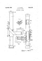
April 29, 1969 F. W. MANN ADJUSTABLE STIL'IS Filed Feb. 20, 1967 FIG! FIG. 2
INVENTOR.
V M) WM United States Patent 3,441,272 ADJUSTABLE STILTS Frederick W. Mann, 222 E. Front St., Waterville, Kans. 65548 Filed Feb. 20, 1967, Ser. No. 622,013 Int. Cl. A63b 25/00 US. Cl. 27270.1 8 Claims ABSTRACT OF THE DISCLOSURE This invention relates to improvements in the use and construction of vertically adjustable stilts.
An object of this invention is to provide an inner support stilt member enhoused by an outer vertically moveable stilt member to which is hinged; a biased, horizontally arcuated foot mount carrying a stilt lock and release mechanism to assure for positive locking engagement with the inner support stilt member.
Still another object of the present invention is to provide for manual adjustment of the foot mount biasing mechanism so as to bias the foot mount either inwardly against the outer stilt support member with the locking mechanism engaging the inner stilt support member forming a rigid stilt or biasing the foot mount outwardly from the outer stilt member extracting the lock and release mechanism from the inner support stilt member and thus freeing the outer stilt member to move vertically on the inner stilt member.
It will now become apparent another object of this invention is to provide for a stilt which is locked, forming a rigid stilt which the user, in use, unlocks for vertical movement; or the same stilt which is unlocked for vertical movement and the user, in use, locks to form a'rigid stilt.
A further object of the present invention is to provide the inner support stilt member with vertically disposed through holes in one wall where by a portion of the wall immediately above and including material forming the upper portion of the hole is depressed to form a vertically extending incline terminating at the lower end thereof in the upper portion of the hole. This portion of the hole is recessed somewhat below the lower portion of the hole, thus forming a ledge like abutment to encounter the stilt lock and release mechanism.
Still another object of the invention is to provide for a pair of stilts which are interchangeable, with all parts performing the same function interchangeable between the stilts; thus simplifying manufacture.
Still additional objects, benefits, and advantages of this invention will become evident from a study of the following detailed description taken in conjunction with the accompanying drawing, in which:
FIGURE 1 is a side elevation view of an adjustable stilt made in accordance with the present invention with the foot mount biased inwardly.
FIGURE 2 is a side elevation, partly broken away, with the foot mount biased outwardly.
FIGURE 3 is a cross sectional view taken along line 33 of FIGURE 2, showing the interior of the foot mount.
Referring now more particularly to the accompanying drawing, where in like numerals of reference indicate like 3,441,272 Patented Apr. 29, 1969 parts through out the different views, numeral 1 indicates the outer stilt member which may be round, rectangular or of any suitable cross section.
Vertically moveable within the outer stilt member 1 is the inner support stilt member 2. The inner stilt member is provided with a cup 3; the inner vertical walls of which frictionally engage the lower, outer walls of the inner member 2. The upper walls of this cup extend above the surface engaging resilient material of the shoe 19 so as to abut the lower end of the outer member and terminate the vertical movement of the inner member into the outer member.
A U shaped shim 17 is attached to the lower inner portion of the outer stilt member with the open end of the U facing the foot mount 5. U shaped shims 18 and 1811 are attached to the upper end of the inner stilt member and are oriented as is shim 17. The outward vertical movement of the inner stilt member is terminated by shim 18 abutting shim 17. Shims 18 and 18a are so spaced apart so as to maintain strength and stability of the stilt upon terminated outward vertical movement of the inner stilt member.
The inner stilt member is provided with a plurality of vertically spaced apart through holes 4 which receive stilt lock and release pin 10, an integral component of foot mount 5. It will be noted holes 4 extend from above cup 3 to just below the U shaped shim 18 so as to provide that the inner stilt member may be locked at any desired height by the user. It also will be noted the portion immediately above and including the upper half arc of holes 4 is recessed inwardly to provide for positive locking and eliminate slippage of lock pin 10 as it engages hole 4.
Lock and release pin 10 is axially aligned, spring loaded and pivotally adjustable within the foot mount 5. Spring loading of the lock and release pin is accomplished by compression spring 12 exerting inward pressure against shoulder 13 of the lock pin. It will be noted that when the user places his Weight on the foot mount, arcing the foot mount inward, the horizontal movement of lock and release pin 10 may be terminated by the lock and release pin not aligning with hole 4; but, instead, abutting the face area of the inner stilt member between holes 4. At this instant the lock and release pin has stopped and the foot mount arcs on inwardly until it is terminated by abutting the outer stilt member; thus the compression spring, in combination with the retaining mechanism, loads the lock and release pin and drives it into hole 4 upon alignment. It will also be noted the insertion depth of lock and release pin 10 into holes 4 is predetermined and maintained by shoulder 13 of the lock and release pin abutting the inner portion of the lock and release pin retaining mechanism 11, which is attached to foot mount 5. The inner hole of this retaining mechanism is vertically elongated to provide for lock and release pin drift as the lock and release pin is inserted or extracted from hole 4. This necessity can be understood if you consider the arc scribed by the foot mount and that scribed by the lock and release pin in sliding through aligning hole 2a in the wall of the outer stilt member. Lock and release pin 10, as pictured in FIGURE 1, has an upper extending portion 10a and an inward extending portion 10b extending parallel to the foot mount.
Outward biasing of the foot mount is accomplished by the thumb slide being in the position as pictured in FIG- URE 2. The upper end of the thumb slide 15 is now engaging the upper most portion of leaf spring 14 ramping it outward, thus exerting bias to rock shaft 8 which in turn biases the foot mount outward. The outward arc of the foot mount is terminated by stop 7.
It will be noted lock and release pin 10 will be maintained at any desired point of rotation by the frictional engagement between the lock and release pin shoulder 19 and the inner, upright portion of the lock and release pin retaining mechanism 11.
The operation of this device will now be readily understood. Assuming the foot mount 5 of a pair of stilts is biased as in FIGURE 1 of the drawing and the lock and release pin 10 is rotated so that portion 10b is above the vfoot mount; the user grasps the outer stilt member 1 at a comfortable height and places his foot upon the foot mount under portion 10b of the lock and release pin 10 and balances his self on the stilts. Upon becoming adept at the starting position and wishing to ascend the user merely raises his foot upward from the foot mount; contacting portion 10b of the lock and release pin and arcing the foot mount outward; extracting the lock and release pin 10 from the hole 4 of the inner member 2; unlocking the stilts and carrying the outer stilt member 1 upward on the inner stilt member 2. Upon reaching a desired stepping height the user again steps on the foot mount, which carries the lock and release pin which engages the inner stilt member; again locking the stilts. Repeated procedure of each stilt will ascend the user to the apex of the stilts. Upon wishing to walk at a desired height the user must avoid arcing the foot mount outward. This is accomplished by maintaining contact with the foot mount by raising the outer stilt member with the hand when taking a step. Upon wishing to descend the user raises his foot into portion 10b and forces the outer stilt member downward until a downward stepping descension is accomplished and halting the outer stilt member with his hands; with his foot continuing downward, the foot mount is reelased and allowed to bias inward; again locking the stilts. Repeated procedure on each stilt will lower the user back to the starting position.
Now assuming the foot mount is biased outward as pictured in FIGURE 2 and the lock and release pin 10 is rotated so portion 10b is at a lower level than the foot mount and assuming the stilts are in the starting position the user grasps the upper portion of each of the outer stilt members and places a foot on each foot mount; arcing the outwardly biased foot mount inwardly; inserting the lock and release pin 10 into hole 4 of the inner stilt member; thus locking the stilts. Upon desiring to ascend the user merely lifts his foot high enough above the foot mount to allow the biased foot mount to are outward; extracting the lock and release pin from the inner member; unlocking the stilts and raising the outer stilt member upward with his hand until a desired step in height is reached; again steps down onto the foot mount, arcing the outward biased foot mount inward; carrying the lock and reelase pin 10 which engaged the inner member; again locking the stilts.
While this invention has been described with particular reference to the construction shown in the drawing and while various changes may be made in the detail construction, it shall be understood that such changes shall be within the spirit and scope of the present invention as defined by the appended claims.
Having thus completely and fully described the invention, what is now claimed as new and desired to be protected by Letters Patent of the United States is:
1. In a device of this class constituting an outer stilt member and an inner support stilt member mounted for vertical movement relative to one another; a biased, horizontally arcuated foot mount; hinged to the lower end of the outer stilt member; said foot mount carrying a stilt lock and release mechanism into and out of engagement with vertically spaced apart through holes in the upright wall of the inner support member; said foot mount biasing means being adjustable to bias the foot mount either inwardly against the outer stilt member or outwardly from said outer stilt member.
2. A vertically adjustable stilt constructed in accordance with claim 1 wherein said foot mount is hinged to are perpendicular to said vertical stilt members.
3. A vertically adjustable stilt constructed in accordance with claim 1 wherein the bias to the foot mount may be manually adjusted.
4. A vertically adjustable stilt constructed in accordance with claim 1 wherein said stilt lock and release mechanism is axially aligned, spring loaded, and pivotally adjustable within said foot mount.
5. A vertically adjustable stilt construction in accordance with claim 1 wherein said stilt lock and release mechanism extends to a point outside of said foot mount and extends parallel to a portion thereof.
6. A vertically adjustable stilt constructed in accordance with claim 1 wherein said stilt lock and release mechanism may be rotated on said foot mount.
7. A vertically adjustable stilt constructed in accord ance with claim 1 wherein said stilt lock and release mechanism is spring loaded relative to said foot mount.
8. A vertically adjustable stilt constructed in accordance with claim 1 wherein a portion of the Wall between said holes of said inner support stilt member is depressed obliquely inward terminating in the upper half are of each hole.
References Cited UNITED STATES PATENTS 1,708,030 4/ 1929 Petersen 27270.2 2,057,013 10/1936 Curtis 27270.1 2,504,922 4/1950 Dowell 27270.1 2,837,335 6/1958 Koening 272-701 ANTON O. OECHSLE, Primary Examiner.
RICHARD W. DIAZ, IR., Assistant Examiner.
Applications Claiming Priority (1)
| Application Number | Priority Date | Filing Date | Title |
|---|---|---|---|
| US62201367A | 1967-02-20 | 1967-02-20 |
Publications (1)
| Publication Number | Publication Date |
|---|---|
| US3441272A true US3441272A (en) | 1969-04-29 |
Family
ID=24492594
Family Applications (1)
| Application Number | Title | Priority Date | Filing Date |
|---|---|---|---|
| US622013A Expired - Lifetime US3441272A (en) | 1967-02-20 | 1967-02-20 | Adjustable stilts |
Country Status (1)
| Country | Link |
|---|---|
| US (1) | US3441272A (en) |
Cited By (7)
| Publication number | Priority date | Publication date | Assignee | Title |
|---|---|---|---|---|
| US3673615A (en) * | 1970-04-27 | 1972-07-04 | Forest M Ellis | Body attached stilts with vertically adjustable steps |
| US4415063A (en) * | 1982-07-26 | 1983-11-15 | James Hutchison | Stilt device |
| US4711446A (en) * | 1986-02-25 | 1987-12-08 | Nielsen Orlan S | Stilt |
| WO1992014518A1 (en) * | 1991-02-25 | 1992-09-03 | Peter Leder | Adjustable stilts |
| US5593373A (en) * | 1995-03-07 | 1997-01-14 | Hale; Russell S. | Economical foot connected stilt assembly |
| FR2754721A1 (en) * | 1996-10-23 | 1998-04-24 | Chafai Djemil | FOOT STUDS |
| US20040107983A1 (en) * | 2002-10-22 | 2004-06-10 | Hsueh-Hu Liao | Joint mechanism |
Citations (4)
| Publication number | Priority date | Publication date | Assignee | Title |
|---|---|---|---|---|
| US1708030A (en) * | 1927-05-02 | 1929-04-09 | Petersen Ludwig | Stilt |
| US2057013A (en) * | 1935-07-08 | 1936-10-13 | Franklin J Curtis | Stilt |
| US2504922A (en) * | 1948-05-17 | 1950-04-18 | Projects Inc | Stilt |
| US2837335A (en) * | 1955-03-16 | 1958-06-03 | Frederick C Koenig | Stilt construction |
-
1967
- 1967-02-20 US US622013A patent/US3441272A/en not_active Expired - Lifetime
Patent Citations (4)
| Publication number | Priority date | Publication date | Assignee | Title |
|---|---|---|---|---|
| US1708030A (en) * | 1927-05-02 | 1929-04-09 | Petersen Ludwig | Stilt |
| US2057013A (en) * | 1935-07-08 | 1936-10-13 | Franklin J Curtis | Stilt |
| US2504922A (en) * | 1948-05-17 | 1950-04-18 | Projects Inc | Stilt |
| US2837335A (en) * | 1955-03-16 | 1958-06-03 | Frederick C Koenig | Stilt construction |
Cited By (8)
| Publication number | Priority date | Publication date | Assignee | Title |
|---|---|---|---|---|
| US3673615A (en) * | 1970-04-27 | 1972-07-04 | Forest M Ellis | Body attached stilts with vertically adjustable steps |
| US4415063A (en) * | 1982-07-26 | 1983-11-15 | James Hutchison | Stilt device |
| US4711446A (en) * | 1986-02-25 | 1987-12-08 | Nielsen Orlan S | Stilt |
| WO1992014518A1 (en) * | 1991-02-25 | 1992-09-03 | Peter Leder | Adjustable stilts |
| US5593373A (en) * | 1995-03-07 | 1997-01-14 | Hale; Russell S. | Economical foot connected stilt assembly |
| FR2754721A1 (en) * | 1996-10-23 | 1998-04-24 | Chafai Djemil | FOOT STUDS |
| US20040107983A1 (en) * | 2002-10-22 | 2004-06-10 | Hsueh-Hu Liao | Joint mechanism |
| US7270138B2 (en) | 2002-10-22 | 2007-09-18 | Hsueh-Hu Liao | Joint mechanism |
Similar Documents
| Publication | Publication Date | Title |
|---|---|---|
| US5052461A (en) | Security gate operable with one hand | |
| US3441272A (en) | Adjustable stilts | |
| AU605910B2 (en) | Security gate operable with one hand | |
| US4415063A (en) | Stilt device | |
| US6273834B1 (en) | Quick-release self-adjusting latch for adjustable basketball goal assembly | |
| US20020121749A1 (en) | Roller skate shoes | |
| CN102378588A (en) | Folding high chair with table | |
| KR100768461B1 (en) | Reformer exercise apparatus anchor bar and carriage stop assembly | |
| KR101078332B1 (en) | weight adjustment apparatus for weight training machine | |
| US2549584A (en) | Motion-picture projection screen stand | |
| US5492292A (en) | Device for supporting and stabilizing furniture | |
| US4856761A (en) | Position adjustable handrail for use along stairways | |
| US20180230747A1 (en) | Ladder stabiliser | |
| US4968071A (en) | Security gate operable with one hand | |
| US20180027937A1 (en) | Extendable sled device and a method for its use | |
| US4939876A (en) | Position adjustable handrail for use along stairways | |
| US3032048A (en) | Crutch | |
| US11795732B2 (en) | Self-locking gate assembly | |
| US20180078845A1 (en) | Snowboard | |
| US1592637A (en) | Lock | |
| KR101605256B1 (en) | Lifting device consisting of a hert-shaped cam | |
| CN223055000U (en) | Sports equipment | |
| US557134A (en) | Island | |
| JPH08131263A (en) | Lifting table | |
| KR101999257B1 (en) | Furniture fall prevention device |