US3441265A - Adjustable clamp - Google Patents
Adjustable clamp Download PDFInfo
- Publication number
- US3441265A US3441265A US594329A US3441265DA US3441265A US 3441265 A US3441265 A US 3441265A US 594329 A US594329 A US 594329A US 3441265D A US3441265D A US 3441265DA US 3441265 A US3441265 A US 3441265A
- Authority
- US
- United States
- Prior art keywords
- slide bar
- sleeve
- movable jaw
- clamp
- jaw member
- Prior art date
- Legal status (The legal status is an assumption and is not a legal conclusion. Google has not performed a legal analysis and makes no representation as to the accuracy of the status listed.)
- Expired - Lifetime
Links
- 125000006850 spacer group Chemical group 0.000 description 9
- 230000007246 mechanism Effects 0.000 description 8
- 230000009471 action Effects 0.000 description 4
- 230000004048 modification Effects 0.000 description 2
- 238000012986 modification Methods 0.000 description 2
- 238000003466 welding Methods 0.000 description 2
- 241000220317 Rosa Species 0.000 description 1
- 229910000831 Steel Inorganic materials 0.000 description 1
- 238000004026 adhesive bonding Methods 0.000 description 1
- 230000006835 compression Effects 0.000 description 1
- 238000007906 compression Methods 0.000 description 1
- 230000000694 effects Effects 0.000 description 1
- 238000004519 manufacturing process Methods 0.000 description 1
- 239000010959 steel Substances 0.000 description 1
Images
Classifications
-
- B—PERFORMING OPERATIONS; TRANSPORTING
- B23—MACHINE TOOLS; METAL-WORKING NOT OTHERWISE PROVIDED FOR
- B23Q—DETAILS, COMPONENTS, OR ACCESSORIES FOR MACHINE TOOLS, e.g. ARRANGEMENTS FOR COPYING OR CONTROLLING; MACHINE TOOLS IN GENERAL CHARACTERISED BY THE CONSTRUCTION OF PARTICULAR DETAILS OR COMPONENTS; COMBINATIONS OR ASSOCIATIONS OF METAL-WORKING MACHINES, NOT DIRECTED TO A PARTICULAR RESULT
- B23Q3/00—Devices holding, supporting, or positioning work or tools, of a kind normally removable from the machine
- B23Q3/02—Devices holding, supporting, or positioning work or tools, of a kind normally removable from the machine for mounting on a work-table, tool-slide, or analogous part
- B23Q3/06—Work-clamping means
-
- B—PERFORMING OPERATIONS; TRANSPORTING
- B23—MACHINE TOOLS; METAL-WORKING NOT OTHERWISE PROVIDED FOR
- B23Q—DETAILS, COMPONENTS, OR ACCESSORIES FOR MACHINE TOOLS, e.g. ARRANGEMENTS FOR COPYING OR CONTROLLING; MACHINE TOOLS IN GENERAL CHARACTERISED BY THE CONSTRUCTION OF PARTICULAR DETAILS OR COMPONENTS; COMBINATIONS OR ASSOCIATIONS OF METAL-WORKING MACHINES, NOT DIRECTED TO A PARTICULAR RESULT
- B23Q2703/00—Work clamping
- B23Q2703/02—Work clamping means
Definitions
- My invention relates generally to clamping devices and is directed particularly to improvements in clamps of the type employed in holding workpieces in relatively fixed position for any purpose or operation in manufacture, such as for the welding, bolting, gluing or fitting together of parts.
- Means including a screw bolt engageable against an edge portion of the support bar is provided for adjustably securing the movable jaw mechanism in place and in clamping engagement with the workpiece to be held. It is the principal object of this invention to improve upon the clamp mechanisms disclosed in the above prior applications by the provision of new and improved mechanism for securing the movable jaw in any adjusted position along the vertical support bar of the clamp structure.
- a more particular object of the invention is to provide an improved clamp of the above nature wherein the movable jaw mechanism includes a screw-threaded clamping handle which clamps directly down upon the workpiece to be held, and through which reactive forces are applied to a relatively movable pinch sleeve member forming part of the movable jaw mechanism for securing the jaw mechanism in fixed relation along the support bar at any position of adjustment therealong.
- Yet another object is to provide an improved clamp of the character described wherein the reactive forces upon clamping are so operative as to more securely fix the movable jaw mechanism with respect to its adjusted position along the support bar, the tighter the workpiece being clamped is clamped in place by the clamping handle.
- This may be considered a servo mechanical device, wherein the clamping pressure feeds back to the holding means upon the bar. Therefore the greater the clamping pressure, the greater the holding means upon the bar.
- the object of the invention is to provide a simple clamp or clamps for almost any application, wherein quick and infinite adjustment is needed, and wherein sure and powerful clamping pressure is needed.
- Yet another object is to provide a clamp wherein the holding components are simple yet do not mar the slide bar.
- Another object of my invention is to provide an adjustable clamp of the character described that can readily and inexpensively be manufactured for the most part of 3,441,265 Patented Apr. 29, 1969 "ice plate steel, and which can be quickly and easily adjusted and locked in clamping position.
- Still another object is to provide an adjustable clamp of the above nature which is simple and compact in structure, while at the same time being powerful and durable in use.
- FIG. 1 illustrates, in side elevation, a form of a clamp embodying the invention
- FIG. 2 is a horizontal cross-sectional view taken along the line 77 of FIG. 1 in the direction of the arrows;
- FIG. 3 is a partial elevational view of the clamp shown in FIG. 1, portions thereof being in vertical section to illustrate mechanical details;
- FIG. 4 is still another form of adjustable clamp em bodyin'g the invention.
- FIG. 5 is a horizontal cross-sectional view taken along the line 1414 of FIG. 4;
- FIG. 6 is a partial view of the clamp illustrated in FIG. 4, portions thereof being in vertical section to illustrate mechanical details;
- FIG. 7 is a vertical cross-sectional view taken along the line 16-16 of FIG. 4 in the direction of the arrows;
- FIG. 8 is a vertical cross-sectional view taken along the line 1717 of FIG. 4 in the direction of the arrows;
- FIG. 9 is a vertical crosssectional view taken along the line 18-18 of FIG. 4 in the direction of the arrows;
- FIG. 10 illustrates, in side elevation, yet another modification of adjustable clamp embodying the invention
- FIG. 11 is a vertical cross-sectional view taken along the line 20-20 of FIG. 10 in the direction of the arrows:
- FIG. 12 is a horizontal cross-sectional view taken along the line 21-21 of FIG. 10 in the direction of the arrows;
- the movable jaw member 34 comprises a pair of spaced, parallel side plate members 36, 37 secured in spaced relation in the front by a first or outer internally threaded, vertically disposed sleeve member 38 welded therebetween, and a second sleeve member 39 also welded therebetween in back of said first sleeve member.
- a splash shield 40 having a front wall 41 and opposed side walls 42, 43 surrounds the front end of the movable jaw member 34 and is ad justably positioned in the vertical direction with respect thereto by means of a bottom plate 41a against which the lower end of a clamp screw 42a abuts.
- the splash shield 40 is normally held in its uppermost position with respect to the clamp screw 42a by means of a compression spring 43a constrained between the underside of the head of an adjustment bolt 44 and the inside of an annular bottom plate 45 welded or otherwise secured against the underside of the sleeve 39, said adjustment bolt being threadingly received in a threaded opening 45a in said bottom plate.
- the underside of the bottom plate 41a of the splash shield 40 has afiixed thereto, as by welding, a jaw grip plate 46 which, as illustrated in FIG. 1, is located vertically above the jaw block 47 of the slide bar and lower jaw member 33.
- the sleeve member 35 comprises a pair of spaced parallel side plate 48, 49 secured in spaced relation at their outer ends by spacer member 50 welded or otherwise affixed therebetween, and a rear spacer member 51 aflixed between said plates at the rear ends thereof.
- the sleeve member 35 is of such thickness as to fit loosely between the side plate members 36, 37 of the movable jaw member 34, and has its forward end pivotally attached thereto as by a bolt 52 extending transversely through openings in said movable jaw member and said sleeve. Pivotal or swinging movement of the sleeve member 35 with respect to the movable jaw member 34 is limited in the counterclockwise direction (as illustrated in FIG.
- a stud screw 54 is threadingly received in a threaded sleeve or nut 55 welded or otherwise affixed between the side plates 36, 37 at upper inner end portions thereof.
- a jam nut 56 threaded on the upwardly and outwardly extending end of the stud screw 54 permits positional adjustment thereof.
- Slidingly received between the side plates 48, 49 of the sleeve member 35 is a wedge member 57 having convergent outer and inner edge surfaces 58, 59, respectively.
- the outer surface 58 of the wedge member 57 bears in face-to-face engagement against the inner edge of the front spaced rnember 50, and the lower end of said wedge member rests against the upper surface of the abutment bar 53. Upward sliding movement of the wedge member 57 is limited by the upper end thereof abutting the lower end of the stud screw 54.
- the vertical support member 79 comprises a rectangular base portion 82 upstanding from which is a slide bar portion 83 of rectangular cross-section.
- the base 82 is adapted to be secure against the flat upper surface of a work table T, and for this purpose is provided with a vertical bore 84 through which a T-bolt 85 slidable along a groove 86 in said work table can extend for securement in adjusted position on the table as by a nut 87.
- the movable jaw member 80 comprises a pair of spaced, parallel side members 88, 89 the front ends of which are held in spaced, parallel relation by a threaded sleeve 90 welded therebetween in vertical disposition. Threadingly received within the sleeve 90 is a threaded stud 91 the upper end of which is provided with an angular cross bar 92 used as a handle to turn down the stud member 91 in clamping engagement against the table T of a workpiece W (see FIG. 4). The rear ends of the spaced parallel side members 88, 89 are inclined somewhat upwardly as seen in FIG.
- the sleeve clamp sleeve member 81 comprises a pair of spaced, parallel side bars 96, 97 so spaced as to slidingly admit therebetween the slide bar portion 83 of the vertical support member 79.
- the side plates 96, 97 of the clamp sleeve member 81 are secured in spaced relation by a vertically extending spacer bar 98.
- the slide bar portion 83 of the vertical support member 79 is received between the side plates 96, 97 of the clamp sleeve member 81 with the front edge of said slide bar portion in face-to-face engagement against the inner edge of the spacer mem ber 98.
- the link rod 101 is located in spaced relation somewhat to the rear edge of the slide bar portion 83 of the vertical support member 79, and besides securing the movable jaw member and clamp sleeve member 81 in interconnected relation, extends through a side opening 103 in a wedge member 104 fitted within said clamp sleeve member between the rear edge of the slide bar portion 83 and the inner inclined edge of the spacer bar 99. As illustrated in FIG.
- the lower end of the threaded stud 108 has aflixed thereto a crank handle 114 for manually turning said stud screw for vertical adjustment of the lower jaw block 111 in clamping a workpiece in place. It will be understood that upon such clamping action, a reactive turning force will be applied to the movable jaw member 80a, effecting locking thereof with respect to the Vertical slide bar member 105 as described in the embodiment of the invention illustrated in FIGS. 4 through 9.
- An adjustable clamp as defined in claim 2 wherein said movable jaw member comprises a pair of spaced, parallel side plate members extending past each side of said slide bar and to the rear thereof, said pivot pin being arranged to the rear of said slide bar.
- An adjustable clamp as defined in claim 2 including mechanism for adjusting the vertical position of said upwardly facing workpiece-engaging member with respect to said lower jaw member.
Description
April 29,1969 H.AL.BERT 3,4 5",
ADJUSTABLE CLAMP Filed 0C1 28, 1966 Sheet of 3.
' 'INVENTOR.
47 /1 erm n :9 /be r 7 April 29, 1969 Filed Oct. 28, I966 H. ALBERT ADJUSTABLE CLAMP INVENTOR. W mer/7 fi/kerf April 29, 1969 'H. ALBERT ADJUSTABLE CLAMP Sheet Filed Oct. 28, 1966 INVENTOR. Herman A/he r United States Patent 3,441,265 ADJUSTABLE CLAMP Herman Albert, 4 Manor Road,
Paterson, NJ. 07514 Continuation-impart of application Ser. No. 452,161,
Apr. 30, 1965. This application Oct. 28, 1966, Ser.
Int. Cl. B25d /02 U.S. Cl. 269-203 5 Claims ABSTRACT OF THE DISCLOSURE This application is a continuation-in-part of my prior application Ser. No. 452,161, filed Apr. 30, 1965, now U.S. Patent No. 3,383,101, which was a continuation-inpart of my prior application Ser. No. 437,151, filed Mar. 4, 1965, now abandoned.
My invention relates generally to clamping devices and is directed particularly to improvements in clamps of the type employed in holding workpieces in relatively fixed position for any purpose or operation in manufacture, such as for the welding, bolting, gluing or fitting together of parts.
Means including a screw bolt engageable against an edge portion of the support bar is provided for adjustably securing the movable jaw mechanism in place and in clamping engagement with the workpiece to be held. It is the principal object of this invention to improve upon the clamp mechanisms disclosed in the above prior applications by the provision of new and improved mechanism for securing the movable jaw in any adjusted position along the vertical support bar of the clamp structure.
A more particular object of the invention is to provide an improved clamp of the above nature wherein the movable jaw mechanism includes a screw-threaded clamping handle which clamps directly down upon the workpiece to be held, and through which reactive forces are applied to a relatively movable pinch sleeve member forming part of the movable jaw mechanism for securing the jaw mechanism in fixed relation along the support bar at any position of adjustment therealong.
Yet another object is to provide an improved clamp of the character described wherein the reactive forces upon clamping are so operative as to more securely fix the movable jaw mechanism with respect to its adjusted position along the support bar, the tighter the workpiece being clamped is clamped in place by the clamping handle.
This may be considered a servo mechanical device, wherein the clamping pressure feeds back to the holding means upon the bar. Therefore the greater the clamping pressure, the greater the holding means upon the bar.
The object of the invention is to provide a simple clamp or clamps for almost any application, wherein quick and infinite adjustment is needed, and wherein sure and powerful clamping pressure is needed.
Yet another object is to provide a clamp wherein the holding components are simple yet do not mar the slide bar.
Another object of my invention is to provide an adjustable clamp of the character described that can readily and inexpensively be manufactured for the most part of 3,441,265 Patented Apr. 29, 1969 "ice plate steel, and which can be quickly and easily adjusted and locked in clamping position.
Still another object is to provide an adjustable clamp of the above nature which is simple and compact in structure, while at the same time being powerful and durable in use.
Other objects, features and advantages of the invention will be apparent from the following description when read with reference to the accompanying drawings. In the drawings, wherein like reference numerals denote corresponding parts throughout the several views:
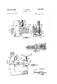
FIG. 1 illustrates, in side elevation, a form of a clamp embodying the invention;
FIG. 2 is a horizontal cross-sectional view taken along the line 77 of FIG. 1 in the direction of the arrows;
FIG. 3 is a partial elevational view of the clamp shown in FIG. 1, portions thereof being in vertical section to illustrate mechanical details;
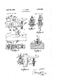
FIG. 4 is still another form of adjustable clamp em bodyin'g the invention;
FIG. 5 is a horizontal cross-sectional view taken along the line 1414 of FIG. 4;
FIG. 6 is a partial view of the clamp illustrated in FIG. 4, portions thereof being in vertical section to illustrate mechanical details;
FIG. 7 is a vertical cross-sectional view taken along the line 16-16 of FIG. 4 in the direction of the arrows;
FIG. 8 is a vertical cross-sectional view taken along the line 1717 of FIG. 4 in the direction of the arrows;
FIG. 9 is a vertical crosssectional view taken along the line 18-18 of FIG. 4 in the direction of the arrows;
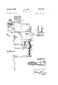
FIG. 10 illustrates, in side elevation, yet another modification of adjustable clamp embodying the invention;
FIG. 11 is a vertical cross-sectional view taken along the line 20-20 of FIG. 10 in the direction of the arrows: and
FIG. 12 is a horizontal cross-sectional view taken along the line 21-21 of FIG. 10 in the direction of the arrows;
Referring now in detail to the drawings, in particular to FIGS. 1 through 3, the same comprises generally, a slide bar and lower jaw member 33 a movable jaw member 34 and a sleeve member 35. The movable jaw member 34 comprises a pair of spaced, parallel side plate members 36, 37 secured in spaced relation in the front by a first or outer internally threaded, vertically disposed sleeve member 38 welded therebetween, and a second sleeve member 39 also welded therebetween in back of said first sleeve member. A splash shield 40 having a front wall 41 and opposed side walls 42, 43 surrounds the front end of the movable jaw member 34 and is ad justably positioned in the vertical direction with respect thereto by means of a bottom plate 41a against which the lower end of a clamp screw 42a abuts. The splash shield 40 is normally held in its uppermost position with respect to the clamp screw 42a by means of a compression spring 43a constrained between the underside of the head of an adjustment bolt 44 and the inside of an annular bottom plate 45 welded or otherwise secured against the underside of the sleeve 39, said adjustment bolt being threadingly received in a threaded opening 45a in said bottom plate. The underside of the bottom plate 41a of the splash shield 40 has afiixed thereto, as by welding, a jaw grip plate 46 which, as illustrated in FIG. 1, is located vertically above the jaw block 47 of the slide bar and lower jaw member 33.
The sleeve member 35 comprises a pair of spaced parallel side plate 48, 49 secured in spaced relation at their outer ends by spacer member 50 welded or otherwise affixed therebetween, and a rear spacer member 51 aflixed between said plates at the rear ends thereof. The sleeve member 35 is of such thickness as to fit loosely between the side plate members 36, 37 of the movable jaw member 34, and has its forward end pivotally attached thereto as by a bolt 52 extending transversely through openings in said movable jaw member and said sleeve. Pivotal or swinging movement of the sleeve member 35 with respect to the movable jaw member 34 is limited in the counterclockwise direction (as illustrated in FIG. 1) by an abutment bar 53 welded between the inner ends of the side plate members 36, 37 at the lower ends thereof. For the purpose hereinafter appearing, a stud screw 54 is threadingly received in a threaded sleeve or nut 55 welded or otherwise affixed between the side plates 36, 37 at upper inner end portions thereof. A jam nut 56 threaded on the upwardly and outwardly extending end of the stud screw 54 permits positional adjustment thereof. Slidingly received between the side plates 48, 49 of the sleeve member 35 is a wedge member 57 having convergent outer and inner edge surfaces 58, 59, respectively. The outer surface 58 of the wedge member 57 bears in face-to-face engagement against the inner edge of the front spaced rnember 50, and the lower end of said wedge member rests against the upper surface of the abutment bar 53. Upward sliding movement of the wedge member 57 is limited by the upper end thereof abutting the lower end of the stud screw 54. Considering now the operation of the embodiment of my invention illustrated in FIGS. 1 through 3, it will be seen that as the movable jaw member 34 is constrained clockwise with respect to the sleeve member 35, through which the vertical slide bar portion 34a of the movable jaw member 34 extends, as occurs when a workpiece (not illustrated) is being clamped, the wedge member 57 will be forced downwardly in the sleeve member 35 to bring its inner edge 59 closer to the inner edge of the rear spacer member 51, thereby to clamp said sleeve member securely in place in preadjusted position suitable for the work piece to be held. Upon release of the workpiece being clamped slight clockwise movement of the movable jaw member 34 will release the wedge member 57 to permit infinite positional adjustment of the sleeve member 35 along the vertical slide bar portion 34a.
Referring now to the fourth embodiment of my invention illustrated in FIGS. 4 through 9, the same comprises, generally, a vertical support member 79, a movable jaw member 80 and a clamp sleeve member 81. The vertical support member 79 comprises a rectangular base portion 82 upstanding from which is a slide bar portion 83 of rectangular cross-section. The base 82 is adapted to be secure against the flat upper surface of a work table T, and for this purpose is provided with a vertical bore 84 through which a T-bolt 85 slidable along a groove 86 in said work table can extend for securement in adjusted position on the table as by a nut 87. The movable jaw member 80 comprises a pair of spaced, parallel side members 88, 89 the front ends of which are held in spaced, parallel relation by a threaded sleeve 90 welded therebetween in vertical disposition. Threadingly received within the sleeve 90 is a threaded stud 91 the upper end of which is provided with an angular cross bar 92 used as a handle to turn down the stud member 91 in clamping engagement against the table T of a workpiece W (see FIG. 4). The rear ends of the spaced parallel side members 88, 89 are inclined somewhat upwardly as seen in FIG. 4, and are secured in spaced, parallel relation at their rear upper end by an internally threaded, vertically extending sleeve 93 threadingly received in which is a threaded stud 94 adjustably secured in place by a lock nut 95 for the purpose hereinafter appearing. The sleeve clamp sleeve member 81 comprises a pair of spaced, parallel side bars 96, 97 so spaced as to slidingly admit therebetween the slide bar portion 83 of the vertical support member 79. The side plates 96, 97 of the clamp sleeve member 81 are secured in spaced relation by a vertically extending spacer bar 98. The rear ends of the side plates 96, 97
are similarly held in spaced relation by a spacer bar 99 welded therebetween, said spacer bar having an inclined inner edge surface 100 extending in the inward direction from top to bottom. The clamp sleeve member 81 is of such overall width as to fit slidingly between the side members 88, 89 of the movable jaw member 80, and is pivotally linked therebetween by a link rod 101 extending transversely through openings in said jaw member and said clamp sleeve member, and fixed in place against axial movement as by cotter pins 102 at each end. As illustrated in FIG. 4, the slide bar portion 83 of the vertical support member 79 is received between the side plates 96, 97 of the clamp sleeve member 81 with the front edge of said slide bar portion in face-to-face engagement against the inner edge of the spacer mem ber 98. The link rod 101 is located in spaced relation somewhat to the rear edge of the slide bar portion 83 of the vertical support member 79, and besides securing the movable jaw member and clamp sleeve member 81 in interconnected relation, extends through a side opening 103 in a wedge member 104 fitted within said clamp sleeve member between the rear edge of the slide bar portion 83 and the inner inclined edge of the spacer bar 99. As illustrated in FIG. 4, upon clamping down upon a workpiece W, reactive counterclockwise turning of the movable jaw member 80 will cause the lower end of the stud 94 to bear down upon the upper end of the wedge member 104, jamming it in place between the outer edge of the slide bar member 83 and the inner inclined edge 100 of the spacer member 99. It will thus be evident that the tighter the workpiece W is clamped in place by the use of the cross-bar handle 92, the greater will be the pinching force exerted by the wedge member 104, thereby to securely fix the movable jaw member 80 in preadjusted position along the slide bar portion 83 of the vertical support member 79. Positional adjustment of the threaded stud 94 permits optimal adjustment of the reactive position at which the movable jaw member 80 effects clamping action with respect to the vertical slide member 83.
FIGS. 10 through 12 illustrate still another embodiment of the invention, which differs from the embodiment illustrated in FIGS. 4 through 9, just described, only in that clamping engagement of the workpiece is effected by manual adjustment of a bottom jaw member. To this end, the vertical slide bar member 105, for example, is formed at its lower end with a forwardlyextending portion 106, the outer end of which has welded or otherwise secured thereto an internally threaded sleeve 107 threadingly received within which is a threaded stud 108. The upper end of the stud 108 bears against the underside of a jaw member 109 secured at its inner end to a rectangular sleeve member 110. Fixed upon the upper surface of the jaw member 109 at the outer end thereof is a lower jaw block 111 in vertical alignment below an upper jaw block member 112 fixed against the underside of the movable jaw member 80a, which upper jaw block member replaces the threaded sleeve 90 and threaded stud 91 of the embodiment of the invention illustrated in FIGS. 4 through 9. The jaw member 109 is resiliently constrained in its lowermost position along the vertical slide bar by means of a tension spring 113 having one end affixed to the underside of said jaw member and the other end afiixed to the upper surface of the forwardly extending portion 106 of the slide bar member 105. The lower end of the threaded stud 108 has aflixed thereto a crank handle 114 for manually turning said stud screw for vertical adjustment of the lower jaw block 111 in clamping a workpiece in place. It will be understood that upon such clamping action, a reactive turning force will be applied to the movable jaw member 80a, effecting locking thereof with respect to the Vertical slide bar member 105 as described in the embodiment of the invention illustrated in FIGS. 4 through 9.
While I have illustrated and described herein only five forms in which my invention may conveniently be embodied in practice, it is to be understood that these forms are given by way of example only and not in a limiting sense. My invention, in brief, comprises all the modifications and embodiments coming Within the scope and spirit of the following claims.
What I claim as new and desire to secure by Letters Patent is:
1. An adjustable clamp comprising, in combination, a vertical slide bar, a lower jaw member fixed with respect to said vertical slide bar at a position laterally spaced therefrom and having an upwardly facing workpieceengaging member, a movable jaw member, a sleeve member surrounding said slide bar and movable therealong, means pivotally interlinking said movable jaw member and said sleeve member for their movement in unison along said slide bar, said movable jaw member having a laterally extending arm portion in vertical alignment with said upwardly extending workpiece-engaging member, vertically adjustable screw-threaded means in said laterally extending portion of said movable jaw member for bearing down on a workpiece positioned on said upwardly facing workpiece-engaging member for clamping said workpiece in place, and means controlled by the reactive turning movement of said movable jaw member upon clamping a workpiece for simultaneously clamp-ing said sleeve member in preselected fixed position along and with respect to said vertical slide bar, said sleeve clamping means comprising a first abutment member in said sleeve member and in face-to-face relative disposition with respect to one edge portion of said slide bar, a second abutment member in spaced relation with respect to an opposite edge portion of said slide bar, and having an inwardly facing edge inclined with respect to said opposite edge portion of said slide bar, and a wedge member disposed within said sleeve member and between said inclined inwardly facing edge and said opposite edge portion of said bar, and means controlled by the turning of said movable jaw member for forcing said wedge member into the space between said inwardly facing edge and said opposite edge portion, and adjustable abutment means between said movable jaw member and an outer end portion of said wedge for controlling the clamping action of said sleeve clamping means.
2. An adjustable clamp comprising, in combination, a vertical slide bar, a lower jaw member fixed with respect to said vertical slide bar at a position laterally spaced therefrom and having an upwardly facing workpieceengaging member, a movable jaw member, a sleeve member surrounding said slide bar and movable therealong, means pivotally interlinking said movable jaw member and said sleeve member for their movement in unison along said slide bar, said jaw member having a laterally extending arm portion in vertical alignment with said upwardly extending workpiece-engaging member, vertically adjustable screw-threaded means in said laterally extending portion of said movable jaw member for hearing down on a workpiece positioned on said upwardly facing workpiece-engaging member for clamping said workpiece in place, and means controlled by the reactive turning movement of said movable jaw member upon clamping a workpiece for simultaneously clamping said sleeve member in preselected fixed position along and with respect to said vertical slide bar, said sleeve clamping means comprising a first abutment member in said sleeve member and in face-to-face relative disposition with respect to one edge portion of said slide bar, a second abutment member in spaced relation with respect to an opposite edge portion of said slide bar, and having an inwardly facing edge inclined with respect to said opposite edge portion of said slide bar, and a wedge member disposed within said sleeve member and between said inclined inwardly facing edge and said opposite edge portion of said bar, and means controlled by the turning of said movable jaw member for forcing said wedge member into the space between said inwardly facing edge and said opposite edge portion, wherein said wedge member includes a side-to-side through opening, and wherein said pivotally interlinking means comprises a pivot pin extending transversely through said wedge opening.
3. An adjustable clamp as defined in claim 2 wherein said movable jaw member comprises a pair of spaced, parallel side plate members extending past each side of said slide bar and to the rear thereof, said pivot pin being arranged to the rear of said slide bar.
4. An adjustable clamp as defined in claim 3 including adjustable abutment means between said movable jaw member and an outer end portion of said wedge for controlling the clamping action of said sleeve clamping means.
5. An adjustable clamp as defined in claim 2 including mechanism for adjusting the vertical position of said upwardly facing workpiece-engaging member with respect to said lower jaw member.
References Cited UNITED STATES PATENTS 140,852 7/ 1873 Sinclair -269-166 1,741,923 12/ 1929 Dohnal 269-171.S 1,948,134 2/ 1934 Rose 269-205 X FOREIGN PATENTS 75,695 6/ 1961 France. 286,042 5/ 1931 Italy.
LESTER M. SWINGLE, Primary Examiner. JAMES F. MCKEOWN, Assistant Examiner.
US. Cl. X.R. 74-20; 250-55
Applications Claiming Priority (1)
| Application Number | Priority Date | Filing Date | Title |
|---|---|---|---|
| US59432966A | 1966-10-28 | 1966-10-28 |
Publications (1)
| Publication Number | Publication Date |
|---|---|
| US3441265A true US3441265A (en) | 1969-04-29 |
Family
ID=24378447
Family Applications (1)
| Application Number | Title | Priority Date | Filing Date |
|---|---|---|---|
| US594329A Expired - Lifetime US3441265A (en) | 1966-10-28 | 1966-10-28 | Adjustable clamp |
Country Status (1)
| Country | Link |
|---|---|
| US (1) | US3441265A (en) |
Cited By (4)
| Publication number | Priority date | Publication date | Assignee | Title |
|---|---|---|---|---|
| US4121815A (en) * | 1976-11-05 | 1978-10-24 | Roy Alan Paterson | Clamps |
| US4572481A (en) * | 1981-10-14 | 1986-02-25 | Chambers Henry B | Releasable clamping assembly for use with hydraulic jacking apparatus |
| US5174553A (en) * | 1990-04-27 | 1992-12-29 | Brian Challis | Adjustable lock mechanism |
| ITFI20120087A1 (en) * | 2012-05-07 | 2013-11-08 | Paolino Bacci Srl | "MULTIPLE WORKING CENTER" |
Citations (4)
| Publication number | Priority date | Publication date | Assignee | Title |
|---|---|---|---|---|
| US140852A (en) * | 1873-07-15 | Improvement in clamps | ||
| US1741923A (en) * | 1928-01-31 | 1929-12-31 | Dohnal Jan | Screw clamp |
| US1948134A (en) * | 1932-02-18 | 1934-02-20 | George W Rose | Clamp |
| FR75695E (en) * | 1959-05-12 | 1961-07-28 | Clamp |
-
1966
- 1966-10-28 US US594329A patent/US3441265A/en not_active Expired - Lifetime
Patent Citations (4)
| Publication number | Priority date | Publication date | Assignee | Title |
|---|---|---|---|---|
| US140852A (en) * | 1873-07-15 | Improvement in clamps | ||
| US1741923A (en) * | 1928-01-31 | 1929-12-31 | Dohnal Jan | Screw clamp |
| US1948134A (en) * | 1932-02-18 | 1934-02-20 | George W Rose | Clamp |
| FR75695E (en) * | 1959-05-12 | 1961-07-28 | Clamp |
Cited By (5)
| Publication number | Priority date | Publication date | Assignee | Title |
|---|---|---|---|---|
| US4121815A (en) * | 1976-11-05 | 1978-10-24 | Roy Alan Paterson | Clamps |
| US4572481A (en) * | 1981-10-14 | 1986-02-25 | Chambers Henry B | Releasable clamping assembly for use with hydraulic jacking apparatus |
| US5174553A (en) * | 1990-04-27 | 1992-12-29 | Brian Challis | Adjustable lock mechanism |
| ITFI20120087A1 (en) * | 2012-05-07 | 2013-11-08 | Paolino Bacci Srl | "MULTIPLE WORKING CENTER" |
| WO2013168062A1 (en) * | 2012-05-07 | 2013-11-14 | Paolino Bacci S.R.L. | Machining center for multiple machining |
Similar Documents
| Publication | Publication Date | Title |
|---|---|---|
| US3397880A (en) | Vise clamp | |
| US1811518A (en) | Clamp | |
| US7114713B2 (en) | Connector assembly for clamping tool and system utilizing same | |
| US4747588A (en) | Universal clamping tool | |
| CZ288225B6 (en) | Pivoting and sliding jack clamp | |
| US3984092A (en) | Article gripping adapter for clamps | |
| US10632592B2 (en) | Quick clamp pipe vise and method | |
| US4331326A (en) | Stud mounted toggle clamp with a secondary release mechanism | |
| US3063707A (en) | Machine shop vise | |
| US3441265A (en) | Adjustable clamp | |
| US3020041A (en) | Vise | |
| US5791213A (en) | Pipe wrench stand | |
| US2988122A (en) | Toggle clamp | |
| US5033724A (en) | Machine tool vise | |
| US3424450A (en) | Shaping template clamp | |
| US2569239A (en) | Jar vise | |
| US5127639A (en) | Adjustable vise | |
| US3630512A (en) | Clamping device, particularly for a machine tool | |
| US4949946A (en) | Quick-acting clamping device | |
| US3266812A (en) | Chuck with work-piece seating means | |
| US3186706A (en) | Vise construction | |
| US3357697A (en) | Bench vise | |
| US5031887A (en) | Locking system for precision vise | |
| US2723579A (en) | Two-way vise | |
| US3383101A (en) | Adjustable clamp |