US3441241A - Bow holder - Google Patents
Bow holder Download PDFInfo
- Publication number
- US3441241A US3441241A US592250A US3441241DA US3441241A US 3441241 A US3441241 A US 3441241A US 592250 A US592250 A US 592250A US 3441241D A US3441241D A US 3441241DA US 3441241 A US3441241 A US 3441241A
- Authority
- US
- United States
- Prior art keywords
- bow
- holder
- top member
- pin
- arrow
- Prior art date
- Legal status (The legal status is an assumption and is not a legal conclusion. Google has not performed a legal analysis and makes no representation as to the accuracy of the status listed.)
- Expired - Lifetime
Links
- 210000003813 thumb Anatomy 0.000 description 12
- 238000003780 insertion Methods 0.000 description 8
- 230000037431 insertion Effects 0.000 description 8
- 230000006378 damage Effects 0.000 description 3
- 210000004247 hand Anatomy 0.000 description 3
- 230000003584 silencer Effects 0.000 description 3
- 238000010276 construction Methods 0.000 description 2
- 239000002184 metal Substances 0.000 description 2
- 238000012986 modification Methods 0.000 description 2
- 230000004048 modification Effects 0.000 description 2
- 239000007779 soft material Substances 0.000 description 2
- 239000002689 soil Substances 0.000 description 2
- 206010013710 Drug interaction Diseases 0.000 description 1
- 208000027418 Wounds and injury Diseases 0.000 description 1
- 230000009471 action Effects 0.000 description 1
- 230000008859 change Effects 0.000 description 1
- 230000003292 diminished effect Effects 0.000 description 1
- 230000030279 gene silencing Effects 0.000 description 1
- 208000014674 injury Diseases 0.000 description 1
- 230000003993 interaction Effects 0.000 description 1
- 238000012423 maintenance Methods 0.000 description 1
- 239000000463 material Substances 0.000 description 1
- 230000007246 mechanism Effects 0.000 description 1
- 239000004033 plastic Substances 0.000 description 1
- 230000000284 resting effect Effects 0.000 description 1
Images

Classifications
-
- F—MECHANICAL ENGINEERING; LIGHTING; HEATING; WEAPONS; BLASTING
- F41—WEAPONS
- F41B—WEAPONS FOR PROJECTING MISSILES WITHOUT USE OF EXPLOSIVE OR COMBUSTIBLE PROPELLANT CHARGE; WEAPONS NOT OTHERWISE PROVIDED FOR
- F41B5/00—Bows; Crossbows
- F41B5/14—Details of bows; Accessories for arc shooting
Definitions
- This invention relates generally to a bow holder, and more particularly, to the creation of a self-supporting bow holder to be used to hold or support a bow, and more particularly, a hunting bow, in a generally upright and fixed position for a multitude of purposes.
- a further object of this invention is to provide means for supporting a bow in a generally upright, fixed, and ready position to eliminate the necessity otherwise of wearying the user by constant holding of the bow, and to eliminate the placing of the bow on the ground.
- a further object of this invention is to provide in particular a support for a hunting bow in a generally upright and fixed position, near ready position, enabling a hunter by how and arrow to place his bow directly in front of his position, and enabling the user, upon the appearance of game, to silently grasp the bow, move the bow silently toward the user with a slight lift, freeing it silently from its holder, and preventing otherwise scuflling noises which usually would frighten off game.
- a further object of this invention is to provide a bow holder which will prevent undue damage to the bow and its finish and its appurtenances while the bow is being used in the field, such damage being that normally caused by placing the bow on the ground in dampness, leaning it against trees, bushes, and shrubs.
- a further object of this invention to provide a bow holder to particularly support a hunting bow in a generally vertical or fixed or ready position with an arrow nocked on the bow string at all times while the hunter waits for game either in or out of a blind.
- the holder can provide for the holding of the bow and nocked arrow with the broad head point pointing away from the user. Since there is no need for the movement of the bow or the arrow until game appears, the chances of accidentally ,causing the arrow to come loose from its nocked position are greatly diminished.
- a further object of the bow holder is to provide means for holding a bow while its user rests, relaxes, eats either in the field or at a target range.
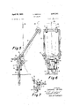
- FIG. 1 is a front elevation of the bow holder in its collapsed or carrying position
- FIG. 2 is a side elevation of FIG. 1
- FIG. 3 is a section taken through the set up holder with pin engaged, and with top member in 'the position shown in FIG. 5
- FIG. 4 is a section taken on line IV--IV through FIG. 3, but with pin retracted
- FIG. 5 is a side elevation showing the holder in its set up position with bow in place
- FIG. 6 is a rear elevation of FIG. 5 with bow in place
- FIG. 7 is a fragmentary side elevation with silencer in contact with lower member after bow has been removed and top member has collapsed.
- the bow holder may be constructed, as previously mentioned, without the thumb screw, and tension means for the automatic collapsing of the holder.
- the bow holder 1 comprises generally a folding rectangular top member 2 equipped with means for enabling it to rotate through an arc of nearly 360.
- the means of rotation are anchored in the top portion of the generally rectangular bottom member 4 of the bow holder, and the top member 2 rotates in a nearly complete circle from one side of the bottom member to the other:
- the top member 2 is equipped with means 5 shown in the drawing as a thumb screw which provides means for adjusting the bow holder to any desirable position, and to accommodate any recurve bow that the user may wish to set in position in the holder, the -bow to be set in the holder in an upright position.
- the means of adjustment 5 is of importance inasmuch as most recurve bows differ slightly in the degree of recurve. Such adjustment also provides a means of compensation to the archer who may fail to insert the lower member vertically in the ground.
- the bow holder 1 is equipped in such manner that the removal of the weight of the bow from its position within the top member 2 during use causes the top member 2 to fall forward and away from the bow.
- the bow holder 1 is further equipped with means 6 to provide that when the top member 2 falls forward and away from the bow, it falls silently.
- the attached drawing shows the silencing members 6 to be two rubber silencers located near the bottom end of the top member, such rubber silencers being generally round and designed to prevent metal to metal contact as the top member 2 falls forward and away from the bow as the bow is removed from the use position of the bow holder.
- the bow holder is further equipped with means 7 and shown as four generally round, adjustable, rubber guides, one set appearing on the top portion of the top member 2, and one set appearing on bracket 8 aflixed to the top portion of the lower member 4.
- the rubber guides 7 are adjustable inwardly and outwardly, and are used to prevent sliding from side to side of the lower portion of the bow when it is inserted in the use position in the bow holder.
- the bow inserted in the holder 2 generally makes physical contact with the top portion of the top member 2 and with the bracket 8 upon which one set of the adjustable rubber guides 7 move back and forth and each set of guides 7 may, following insertion of the bow, be pushed inwardly to rest easily against the sides of the bow.
- the silencers 6 may be equipped in such manner as to stop the forward fall of the top member 2 in a position at an approximate right angle to the bottom member 4 by causing the silencers to come in physical contact with and be stopped by the bracket 8 upon which one set of adjustable rubber guides 7 ride.
- the rubber silencers 6 are also adjustable in that they may be raised and lowered on the top member 2 and may be of varying sizes to stop the forward movement of the top member 2 in any desirable position.
- the top portion of the member 4 is equipped with tension means to hold the top member in position while setting the top member 2 in proper position with respect to the bottom member 4 for the insertion of and the holding of a recurve bow.
- the tension means comprises a knurled, threaded nut 9, a pin 10, a rubber washer 11, and a tension spring 12.
- the tension means holds the top member 2 in position until the bow is removed from the holder, and through the action of the spring 12 causes the release of the top member simultaneously with the removal of the bow permitting the top member 2 to fall forward and away from the bow itself.
- a thumb screw inserted in a cylindrical member 13, and which cylindrical member is equipped with a depression 14 designed to receive pin 10.
- the thumb screw is equipped in such manner as when tightened to cause the thumb screw 5 and the cylindrical member 13 to rotate in unison with the top member 2.
- the loosening of the thumb screw 5 permits the top member 2 to rotate freely without causing the cylindrical member 13 and the thumb screw to rotate simultaneously.
- the thumb screw may be tightened to lock the top portion 2 in the proper position or angle in respect to the lower portion 4 to receive the bow.
- the depression 14 is lined in such way as to receive the upper portion of pin which when engaged in the depression, holds pin 10 in the depression while the force of the bow is being applied forwardly on the top member 2 and backwardly on the bracket 8.
- the position of the bow may be adjusted by loosening thumb screw 5, and rotating the bow and top member 2 to near vertical position, and then tightening the thumb screw 5.
- nut 9 may be loosened to provide the means and opportunity for pin 10 to retract from depression 14 when the frictional engagement between pin 10 and depression 14 is eliminated by removal of the bow, the force of spring 12 causing the retraction.
- the bow during set-up position holds top member 2 in its position until the bow is removed.
- member 2 is free to fall in rotation pattern, and when it falls, silencer 6 stops the forward fall of member 2 in the position shown in FIG.
- the lower portion of the holder comprises rod-like legs for insertion into the ground, and the top portion may be made of rod-like welded material, all of the rods on the top and lower portion of the holder generally to be coated with either plastic or rubberized for the general purpose of preventing slippage and noise and to protect the bow itself from undue wear.
- the knurled nut 9 may be loosened several turns after final adjustment and setting of the bow has been made which will place the entire tension mechanism in a position to release the pin 10 from the depression 14 upon removal of the bow.
- a variation of the above-styled bow holder may comprise a lower member in the same general shape as the lower member in the embodiment described together with a top member generally rectangular, and providing means for the rotation of the top member through on one side of the lower member, and eliminating the tension means described in the foregoing embodiment.
- a holder which will receive and hold a bow in the generally vertical position, and in the ready to use position.
- a bow holder having means of adjustment whereby the upper portion of the holder may be set at varied angles to the lower portion of the holder to receive various types of recurve bows, and to hold such various types of recurve bows.
- a bow holder which collapses in such manner as to permit the upper portion and lower portion to be folded together for easy carrying and storage.
- a bow holder with means for inserting the holder into the ground, means for silent operation and adjustable means for preventing movement of the bow in the holder.
- a collapsible bow holder comprising vertical means equipped for insertion into the soil or other soft material, and forming a unit member for aflixation to other means designed for operational rotation through an arc around the vertical means to create multiple positions for receiving a bow frictionally engaged against the vertical and the rotating members, said vertical means and said rotating means being equipped with further means for silently stopping the rotation of the rotating member, and having further means provided for the manual or automatic rotation of the rotating member aforedescn'bed, all disposed to receive and hold a bow in ready, near perpendicular fashion by frictional inter-action of the bow against the vertical and rotating members, and disposed for silent removal of the bow and either manual or automatic collapse of the upper member upon withdrawal of the bow from ready, near perpendicular position, and corresponding release of frictional engagement of the bow against the vertical and rotating members.
- a collapsible bow holder vertical means equipped for insertion into the soil or other soft material, and being attached to a rotating upper member, the upper member and lower member being equipped to receive a bow frictionally engaged by counterforce against the upper and lower members, the upper member being afiixed to the lower member for rotation about the lower member, a bracket affixed near the top portion of the lower member and having adjustable bow guides fitted thereon, silencers affixed to the upper member and arranged for contact with the bracket aflixed to the lower member for silent collapse, means for setting the rotating upper member in varied fixed positions to receive a bow frictionally engaged against the upper and lower members, and means providing for either manual or automatic collapse of the upper member upon withdrawal of bow from the holders ready position, and corresponding release of frictional engagement of the bow against the upper and lower members.
- a collapsing, folding bow holder comprising a lower member having legs for insertion into the ground, an upper member aflixed to the upper portion of the lower member and disposed for rotation about the lower member, means for limiting the rotation of the upper member, means for holding the upper member in fixed position, adjustable means for stablizing the bow in the bow holder comprising adjustable rubber stoppers disposed at the upper portions of both members, silencers disposed on the upper member for contact with the lower member upon collapse of the upper member, means for providing automatic collapse of the holder upon removal of the bow and comprising a pin disposed for manual insertion into a recess provided in the rotating portion of the upper member and means for forceably disengaging the pin from such recess upon removal of the bow from the holder, thereby permitting automatic collapse of the upper member, and adjustable means for establishing the set position of the upper member to receive the bow.
Landscapes
- Engineering & Computer Science (AREA)
- General Engineering & Computer Science (AREA)
- Orthopedics, Nursing, And Contraception (AREA)
Description
April 29, 1969 L. BROOKS 3,441,241
BOW HOLDER Filed Nov. 5, 1966 0 BY g 4 f s /& INVENTORY m 9 Leonard Brook:
v H/S ATTORNEY A ril 29, 1969 1.. BROOKS BOW HOLDER Filed Nov. 5, 1966 Sheet INVENTOR.
Leonard Brook:
H/S ATTORNEY v United States Patent 3,441,241 BOW HOLDER Leonard Brooks, 108 Center Ave., Follansbee, W. Va. 26037 Filed Nov. 3, 1966, Ser. No. 592,250 Int. Cl. A45f 3/44 US. Cl. 248-156 3 Claims ABSTRACT OF THE DISCLOSURE This invention relates generally to a bow holder, and more particularly, to the creation of a self-supporting bow holder to be used to hold or support a bow, and more particularly, a hunting bow, in a generally upright and fixed position for a multitude of purposes.
It has as its principal object to provide a means for supporting a bow, and more particularly, a hunting bow, in a vertical and fixed position While relieving the user of the bow to utilize his hands freely or to protect his hands from foul weather, and yet provide the means for silent removal of the bow from ready position, and use it in such manner as may then be desirable.
A further object of this invention is to provide means for supporting a bow in a generally upright, fixed, and ready position to eliminate the necessity otherwise of wearying the user by constant holding of the bow, and to eliminate the placing of the bow on the ground.
A further object of this invention is to provide in particular a support for a hunting bow in a generally upright and fixed position, near ready position, enabling a hunter by how and arrow to place his bow directly in front of his position, and enabling the user, upon the appearance of game, to silently grasp the bow, move the bow silently toward the user with a slight lift, freeing it silently from its holder, and preventing otherwise scuflling noises which usually would frighten off game.
A further object of this invention is to provide a bow holder which will prevent undue damage to the bow and its finish and its appurtenances while the bow is being used in the field, such damage being that normally caused by placing the bow on the ground in dampness, leaning it against trees, bushes, and shrubs.
Ordinarily, users of a bow and arrow, and particularly bow and arrow hunters, during periods of waiting for game, either in or out of a blind, find it necessary to place their bows against the blind, against a tree, against a shrub, or flat on the ground. The alternative to this type of placing of the bow is the constant holding of it during the period the hunter waits for the appearance of game. In the event that the user continues to hold the bow in foul weather, the hands can become extremely cold and/ or wet, all of which materially contributes to inaccurate using of the bow and arrow when the use becomes necessary. It is also usual for a bow hunter who continues to hold his bow during periods of waiting for game to appear, to keep an arrow nocked on his bow string, Because there is considerable movement of the bow and nocked arrow if the hunter continues to hold it in his hand, it is likely that the user of the bow and arrow will act in such manner as to cause the arrow to fall from its position, and in some cases, to inflict injury on the user particularly when a sharp, broad head arrow is nocked on the bow string.
It is, therefore, a further object of this invention to provide a bow holder to particularly support a hunting bow in a generally vertical or fixed or ready position with an arrow nocked on the bow string at all times while the hunter waits for game either in or out of a blind. The holder can provide for the holding of the bow and nocked arrow with the broad head point pointing away from the user. Since there is no need for the movement of the bow or the arrow until game appears, the chances of accidentally ,causing the arrow to come loose from its nocked position are greatly diminished.
A further object of the bow holder is to provide means for holding a bow while its user rests, relaxes, eats either in the field or at a target range.
It is a further object of this invention to provide means for holding a bow in the manner aforesaid, and which can,.be folded easily for carrying either in the pocket of the user or in a small utility bag.
The foregoing are examples of the advantages and objects of this invention, and are made without consideration of such additional advantages as ease of use, case of maintenance, and its inherent facility for meeting the needs of bow hunters.
These and other objects and advantages of the bow holder will become apparent from the following description taken in connection with the accompanying drawing in which FIG. 1 is a front elevation of the bow holder in its collapsed or carrying position; FIG. 2 is a side elevation of FIG. 1; FIG. 3 is a section taken through the set up holder with pin engaged, and with top member in 'the position shown in FIG. 5; and FIG. 4 is a section taken on line IV--IV through FIG. 3, but with pin retracted; FIG. 5 is a side elevation showing the holder in its set up position with bow in place; FIG. 6 is a rear elevation of FIG. 5 with bow in place; FIG. 7 is a fragmentary side elevation with silencer in contact with lower member after bow has been removed and top member has collapsed.
While this particular invention is susceptible of various modifications and alternative constructions, it is shown here, and will hereinafter be described in a preferred embodiment with mention to be made of another embodiment which eliminates the necessity of the thumb screw and tension means hereinafter specifically described. It is not intended that this invention necessarily be limited to the specific disclosure made, but, on the contrary, is intended to cover all modifications and alternative constructions falling within the spirit and scope of this invention as defined in this specification and in the appended claims. For instance, the bow holder may be constructed, as previously mentioned, without the thumb screw, and tension means for the automatic collapsing of the holder.
As shown herein, however, for purposes of disclosure the bow holder 1 comprises generally a folding rectangular top member 2 equipped with means for enabling it to rotate through an arc of nearly 360. The means of rotation are anchored in the top portion of the generally rectangular bottom member 4 of the bow holder, and the top member 2 rotates in a nearly complete circle from one side of the bottom member to the other: The top member 2 is equipped with means 5 shown in the drawing as a thumb screw which provides means for adjusting the bow holder to any desirable position, and to accommodate any recurve bow that the user may wish to set in position in the holder, the -bow to be set in the holder in an upright position. The means of adjustment 5 is of importance inasmuch as most recurve bows differ slightly in the degree of recurve. Such adjustment also provides a means of compensation to the archer who may fail to insert the lower member vertically in the ground.
The bow holder 1 is equipped in such manner that the removal of the weight of the bow from its position within the top member 2 during use causes the top member 2 to fall forward and away from the bow. The bow holder 1 is further equipped with means 6 to provide that when the top member 2 falls forward and away from the bow, it falls silently. The attached drawing shows the silencing members 6 to be two rubber silencers located near the bottom end of the top member, such rubber silencers being generally round and designed to prevent metal to metal contact as the top member 2 falls forward and away from the bow as the bow is removed from the use position of the bow holder.
The bow holder is further equipped with means 7 and shown as four generally round, adjustable, rubber guides, one set appearing on the top portion of the top member 2, and one set appearing on bracket 8 aflixed to the top portion of the lower member 4. The rubber guides 7 are adjustable inwardly and outwardly, and are used to prevent sliding from side to side of the lower portion of the bow when it is inserted in the use position in the bow holder. The bow inserted in the holder 2 generally makes physical contact with the top portion of the top member 2 and with the bracket 8 upon which one set of the adjustable rubber guides 7 move back and forth and each set of guides 7 may, following insertion of the bow, be pushed inwardly to rest easily against the sides of the bow.
The silencers 6 may be equipped in such manner as to stop the forward fall of the top member 2 in a position at an approximate right angle to the bottom member 4 by causing the silencers to come in physical contact with and be stopped by the bracket 8 upon which one set of adjustable rubber guides 7 ride.
The rubber silencers 6 are also adjustable in that they may be raised and lowered on the top member 2 and may be of varying sizes to stop the forward movement of the top member 2 in any desirable position. The top portion of the member 4 is equipped with tension means to hold the top member in position while setting the top member 2 in proper position with respect to the bottom member 4 for the insertion of and the holding of a recurve bow. The tension means comprises a knurled, threaded nut 9, a pin 10, a rubber washer 11, and a tension spring 12. The tension means holds the top member 2 in position until the bow is removed from the holder, and through the action of the spring 12 causes the release of the top member simultaneously with the removal of the bow permitting the top member 2 to fall forward and away from the bow itself. In the top portion of the lower member, and partially integrated with the rotating means is a thumb screw inserted in a cylindrical member 13, and which cylindrical member is equipped with a depression 14 designed to receive pin 10.
The thumb screw is equipped in such manner as when tightened to cause the thumb screw 5 and the cylindrical member 13 to rotate in unison with the top member 2. The loosening of the thumb screw 5 permits the top member 2 to rotate freely without causing the cylindrical member 13 and the thumb screw to rotate simultaneously. When the top member 2 is being set in position to receive a bow, the thumb screw may be tightened to lock the top portion 2 in the proper position or angle in respect to the lower portion 4 to receive the bow. The depression 14 is lined in such way as to receive the upper portion of pin which when engaged in the depression, holds pin 10 in the depression while the force of the bow is being applied forwardly on the top member 2 and backwardly on the bracket 8. The force of the bow forwardly on the top portion of top member 2 while the cylindrical member 13 and thumb screw 5 rotate simultaneously with the top member, causes the forward side of depression 14 to frictionally engage the forward side of pin 10 and hold the pin in the engaged position. When the bow is removed from the holder, and the forward force of the bow is removed from the top portion of the top member 2, the force of spring 12 overcomes the force of rotating member 2 and automatically causes the pin 10 to release from the depression 14 and the top member rotates forward and away from the bow.
operationally, the entire unit is pushed into the ground until pin 10 is in a position just above the level of the ground. The top member is then rotated upwardly and held in position as shown in FIG. 5 on the attached drawings. Threaded nut 9 is then tightened to engage pin 10 in depression 14. The bow is then set in place as shown in FIG. 5, and as hereinbefore described. The rubber guides 7 are then adjusted inwardly against the sides of the bow in order to steady it in its relatively vertical position. Both bow 15 and string 16 at this point are in the relatively vertical position. Lower member 4 at this point is also in the relatively vertical position. In the event that lower member 4 is inserted off vertical, or in the event of change in the degree of recurve of the bow, the position of the bow may be adjusted by loosening thumb screw 5, and rotating the bow and top member 2 to near vertical position, and then tightening the thumb screw 5. When the set-up is in this position, nut 9 may be loosened to provide the means and opportunity for pin 10 to retract from depression 14 when the frictional engagement between pin 10 and depression 14 is eliminated by removal of the bow, the force of spring 12 causing the retraction. The bow during set-up position holds top member 2 in its position until the bow is removed. When the bow is removed, member 2 is free to fall in rotation pattern, and when it falls, silencer 6 stops the forward fall of member 2 in the position shown in FIG. 7 with the silencer 6 resting in contact with bracket 8. For resetting the bow in the position of FIG 5, user rotates top member upwardly to the position of FIG 5 while engaging pin 10 in recess 14 manually until frictional engagement is caused between pin 10 and recess 14 by insertion of the bow.
The lower portion of the holder comprises rod-like legs for insertion into the ground, and the top portion may be made of rod-like welded material, all of the rods on the top and lower portion of the holder generally to be coated with either plastic or rubberized for the general purpose of preventing slippage and noise and to protect the bow itself from undue wear.
For satisfactory operation of the bow holder, the knurled nut 9 may be loosened several turns after final adjustment and setting of the bow has been made which will place the entire tension mechanism in a position to release the pin 10 from the depression 14 upon removal of the bow.
A variation of the above-styled bow holder may comprise a lower member in the same general shape as the lower member in the embodiment described together with a top member generally rectangular, and providing means for the rotation of the top member through on one side of the lower member, and eliminating the tension means described in the foregoing embodiment.
It seems apparent from the foregoing description that I, Leonard J. Brooks, have perfected a bow holder which provides the following:
(1) A holder which will receive and hold a bow in the generally vertical position, and in the ready to use position.
(2) Automatic means for collapsing the bow holder upon removal of the bow, such collapse to be accomplished without noise.
(3) A bow holder having means of adjustment whereby the upper portion of the holder may be set at varied angles to the lower portion of the holder to receive various types of recurve bows, and to hold such various types of recurve bows.
(4) A bow holder which collapses in such manner as to permit the upper portion and lower portion to be folded together for easy carrying and storage.
(5) A bow holder with means for inserting the holder into the ground, means for silent operation and adjustable means for preventing movement of the bow in the holder.
I claim:
1. A collapsible bow holder comprising vertical means equipped for insertion into the soil or other soft material, and forming a unit member for aflixation to other means designed for operational rotation through an arc around the vertical means to create multiple positions for receiving a bow frictionally engaged against the vertical and the rotating members, said vertical means and said rotating means being equipped with further means for silently stopping the rotation of the rotating member, and having further means provided for the manual or automatic rotation of the rotating member aforedescn'bed, all disposed to receive and hold a bow in ready, near perpendicular fashion by frictional inter-action of the bow against the vertical and rotating members, and disposed for silent removal of the bow and either manual or automatic collapse of the upper member upon withdrawal of the bow from ready, near perpendicular position, and corresponding release of frictional engagement of the bow against the vertical and rotating members.
2. *In a collapsible bow holder vertical means equipped for insertion into the soil or other soft material, and being attached to a rotating upper member, the upper member and lower member being equipped to receive a bow frictionally engaged by counterforce against the upper and lower members, the upper member being afiixed to the lower member for rotation about the lower member, a bracket affixed near the top portion of the lower member and having adjustable bow guides fitted thereon, silencers affixed to the upper member and arranged for contact with the bracket aflixed to the lower member for silent collapse, means for setting the rotating upper member in varied fixed positions to receive a bow frictionally engaged against the upper and lower members, and means providing for either manual or automatic collapse of the upper member upon withdrawal of bow from the holders ready position, and corresponding release of frictional engagement of the bow against the upper and lower members.
3. A collapsing, folding bow holder comprising a lower member having legs for insertion into the ground, an upper member aflixed to the upper portion of the lower member and disposed for rotation about the lower member, means for limiting the rotation of the upper member, means for holding the upper member in fixed position, adjustable means for stablizing the bow in the bow holder comprising adjustable rubber stoppers disposed at the upper portions of both members, silencers disposed on the upper member for contact with the lower member upon collapse of the upper member, means for providing automatic collapse of the holder upon removal of the bow and comprising a pin disposed for manual insertion into a recess provided in the rotating portion of the upper member and means for forceably disengaging the pin from such recess upon removal of the bow from the holder, thereby permitting automatic collapse of the upper member, and adjustable means for establishing the set position of the upper member to receive the bow.
References Cited UNITED STATES PATENTS 2,593,789 4/1952 Pearson 248l56 XR 3,286,961 11/1966 Mandolare 24812'2XR ROY D. FRAZIER, Primary Examiner.
J. FRANKLIN FOSS, Assistant Examiner.
US. Cl. X.R. 248l22
Applications Claiming Priority (1)
| Application Number | Priority Date | Filing Date | Title |
|---|---|---|---|
| US59225066A | 1966-11-03 | 1966-11-03 |
Publications (1)
| Publication Number | Publication Date |
|---|---|
| US3441241A true US3441241A (en) | 1969-04-29 |
Family
ID=24369923
Family Applications (1)
| Application Number | Title | Priority Date | Filing Date |
|---|---|---|---|
| US592250A Expired - Lifetime US3441241A (en) | 1966-11-03 | 1966-11-03 | Bow holder |
Country Status (1)
| Country | Link |
|---|---|
| US (1) | US3441241A (en) |
Cited By (16)
| Publication number | Priority date | Publication date | Assignee | Title |
|---|---|---|---|---|
| US3584820A (en) * | 1969-01-31 | 1971-06-15 | John A Butcher Sr | Archery bow stand |
| US3991780A (en) * | 1976-02-10 | 1976-11-16 | Maroski Jr Frank M | Combination archery bow stand, walking cane and animal dragging device |
| US4360179A (en) * | 1980-06-30 | 1982-11-23 | Roberts Theodore E | Archery bow stands |
| US4936415A (en) * | 1989-10-10 | 1990-06-26 | Williams Ralph D | Bow holder for a tree stand |
| US4957229A (en) * | 1990-01-02 | 1990-09-18 | Freeman Lowell J D | Vehicle mounted archery bow holder |
| US4993398A (en) * | 1989-10-27 | 1991-02-19 | Wallace James R | Archery bow support stand |
| US5111800A (en) * | 1990-12-17 | 1992-05-12 | Reynolds Gary E | Bowhunter's ground bow holder |
| US5360190A (en) * | 1992-06-23 | 1994-11-01 | Limrak Industries, Inc. | Archery bow-mounting holder |
| USD355694S (en) | 1993-03-15 | 1995-02-21 | Stafford Jr J R | Rest for a hunting bow |
| USD382034S (en) * | 1996-03-14 | 1997-08-05 | Arthur John Dullinger | Archer's bow stand |
| US5806508A (en) * | 1997-04-08 | 1998-09-15 | Stempien; Mary Ann | Archery bow holder |
| US6205992B1 (en) | 1999-12-04 | 2001-03-27 | Randy Meeks | Adjustable stand for an archery bow |
| US6726160B1 (en) * | 2003-05-28 | 2004-04-27 | Duncan R. Buchanan, Jr. | Adjustable bow stand |
| USD582744S1 (en) * | 2004-12-15 | 2008-12-16 | Atlas Copco Tools Ab | Support structure for torque delivering spindle units for tightening screw joints |
| US20100019111A1 (en) * | 2007-10-04 | 2010-01-28 | Bean Ron M | Device and method for securing a bow |
| US20220155038A1 (en) * | 2020-11-13 | 2022-05-19 | Mcp Ip, Llc | Archery Bow Stand |
Citations (2)
| Publication number | Priority date | Publication date | Assignee | Title |
|---|---|---|---|---|
| US2593789A (en) * | 1946-03-25 | 1952-04-22 | Ben Pearson Inc | Support for archery equipment |
| US3286961A (en) * | 1964-08-21 | 1966-11-22 | Dominick A Mandolare | Stand, bow holder and quiver for archery |
-
1966
- 1966-11-03 US US592250A patent/US3441241A/en not_active Expired - Lifetime
Patent Citations (2)
| Publication number | Priority date | Publication date | Assignee | Title |
|---|---|---|---|---|
| US2593789A (en) * | 1946-03-25 | 1952-04-22 | Ben Pearson Inc | Support for archery equipment |
| US3286961A (en) * | 1964-08-21 | 1966-11-22 | Dominick A Mandolare | Stand, bow holder and quiver for archery |
Cited By (18)
| Publication number | Priority date | Publication date | Assignee | Title |
|---|---|---|---|---|
| US3584820A (en) * | 1969-01-31 | 1971-06-15 | John A Butcher Sr | Archery bow stand |
| US3991780A (en) * | 1976-02-10 | 1976-11-16 | Maroski Jr Frank M | Combination archery bow stand, walking cane and animal dragging device |
| US4360179A (en) * | 1980-06-30 | 1982-11-23 | Roberts Theodore E | Archery bow stands |
| US4936415A (en) * | 1989-10-10 | 1990-06-26 | Williams Ralph D | Bow holder for a tree stand |
| US4993398A (en) * | 1989-10-27 | 1991-02-19 | Wallace James R | Archery bow support stand |
| US4957229A (en) * | 1990-01-02 | 1990-09-18 | Freeman Lowell J D | Vehicle mounted archery bow holder |
| US5111800A (en) * | 1990-12-17 | 1992-05-12 | Reynolds Gary E | Bowhunter's ground bow holder |
| US5360190A (en) * | 1992-06-23 | 1994-11-01 | Limrak Industries, Inc. | Archery bow-mounting holder |
| USD355694S (en) | 1993-03-15 | 1995-02-21 | Stafford Jr J R | Rest for a hunting bow |
| USD382034S (en) * | 1996-03-14 | 1997-08-05 | Arthur John Dullinger | Archer's bow stand |
| US5806508A (en) * | 1997-04-08 | 1998-09-15 | Stempien; Mary Ann | Archery bow holder |
| US6205992B1 (en) | 1999-12-04 | 2001-03-27 | Randy Meeks | Adjustable stand for an archery bow |
| US6726160B1 (en) * | 2003-05-28 | 2004-04-27 | Duncan R. Buchanan, Jr. | Adjustable bow stand |
| USD582744S1 (en) * | 2004-12-15 | 2008-12-16 | Atlas Copco Tools Ab | Support structure for torque delivering spindle units for tightening screw joints |
| US20100019111A1 (en) * | 2007-10-04 | 2010-01-28 | Bean Ron M | Device and method for securing a bow |
| US8882070B2 (en) * | 2007-10-04 | 2014-11-11 | Ron M. Bean | Device and method for securing a bow |
| US20220155038A1 (en) * | 2020-11-13 | 2022-05-19 | Mcp Ip, Llc | Archery Bow Stand |
| US12173983B2 (en) * | 2020-11-13 | 2024-12-24 | Mcp Ip, Llc | Archery bow stand |
Similar Documents
| Publication | Publication Date | Title |
|---|---|---|
| US3441241A (en) | Bow holder | |
| US5050332A (en) | Fish hooking device | |
| US5967475A (en) | Hunting bow hanger | |
| US5806508A (en) | Archery bow holder | |
| US9976693B1 (en) | Adjustable mounting device for hunting weaponry | |
| US5317826A (en) | Rifle and pistol rest | |
| US4318390A (en) | Arrow retainer | |
| US6086031A (en) | Gun and beverage support system | |
| US9593903B1 (en) | Bow and arrow hunting accessory device | |
| US3159366A (en) | Holder for a fishing rod | |
| US3017874A (en) | Bow magazine | |
| US6948690B1 (en) | Archery bow steady rest and holder | |
| US4877007A (en) | Sling bow | |
| US3527354A (en) | Water ski rack | |
| US5009215A (en) | Arrow rest and holder apparatus | |
| US2722958A (en) | Quiver | |
| US6244556B1 (en) | Bow holder | |
| US5310150A (en) | Tree mounted archery bow holder | |
| US9426972B2 (en) | Self hook setting rod holder | |
| US8444106B1 (en) | Stake-mounted turkey pot call holder | |
| US5460150A (en) | Repeating elastic band shooting gun | |
| US3114215A (en) | Collapsible easel | |
| US5697183A (en) | Fishing rod holding device | |
| US4873963A (en) | Arrow sling device, and methods of constructing and utilizing same | |
| US3601919A (en) | Fishing rod and reel holder for boat and land fishing |