US3441239A - Survey rod holder - Google Patents
Survey rod holder Download PDFInfo
- Publication number
- US3441239A US3441239A US626828A US3441239DA US3441239A US 3441239 A US3441239 A US 3441239A US 626828 A US626828 A US 626828A US 3441239D A US3441239D A US 3441239DA US 3441239 A US3441239 A US 3441239A
- Authority
- US
- United States
- Prior art keywords
- survey rod
- survey
- ground
- clamps
- post
- Prior art date
- Legal status (The legal status is an assumption and is not a legal conclusion. Google has not performed a legal analysis and makes no representation as to the accuracy of the status listed.)
- Expired - Lifetime
Links
- 238000010276 construction Methods 0.000 description 2
- 238000003780 insertion Methods 0.000 description 2
- 230000037431 insertion Effects 0.000 description 2
- 230000015556 catabolic process Effects 0.000 description 1
- 238000004519 manufacturing process Methods 0.000 description 1
Images
Classifications
-
- G—PHYSICS
- G01—MEASURING; TESTING
- G01C—MEASURING DISTANCES, LEVELS OR BEARINGS; SURVEYING; NAVIGATION; GYROSCOPIC INSTRUMENTS; PHOTOGRAMMETRY OR VIDEOGRAMMETRY
- G01C15/00—Surveying instruments or accessories not provided for in groups G01C1/00 - G01C13/00
- G01C15/02—Means for marking measuring points
- G01C15/06—Surveyors' staffs; Movable markers
Definitions
- a device for holding a survey rod in an upstanding position including a vertical rod having a lower end pointed so as to be readily received into the ground, the rod having an upper and lower clamp for securing a survey rod thereto and additionally having a foot rest along one side for purpose of allowing an operator to push the device with his foot into the ground wherever the ground is too hard for pushing the device by the hands alone.
- This invention relates generally to surveying equipment. More specifically it relates to survey rods and supporting devices for survey rods.
- Another object of the present invention is to provide a survey rod holder having means for being supported within the ground.
- Yet another object of the present invention is to provide a survey rod holder having a foot rest so as to allow an operator to force the device with his foot into the ground so as to provide stability to the device for supporting a survey rod.
- Yet another object of the present invention is to provide a survey rod holder having a pair of spaced apart clamps so as to secure a survey rod thereto at a selected elevation respective thereto.
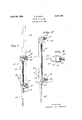
- FIGURE 1 is a prespective view of the present invention shown in operative use
- FIGURE 2 is a side elevation view and shown partly in cross-section as viewed along line 2-2 of FIGURE 1,
- FIGURE 3 is a top plan view thereof.
- the reference numeral represents a survey rod holder of the present invention wherein there is an elongated post 11 of circular cross-sectional configuration and which has a lower end 12 that is tapered to a point so that the same may be easily introduced into a ground 13.
- a clamp 14 is secured at the upper end of the post 11 and a lower clamp 15 is secured at an intermediate point between the opposite ends of the post, the lower clamp being located adjacent the base of the tapered end 12.
- Each of the clamps 14 and 15 comprise a generally U-shaped frame rigidly afiixed to the post 11, each frame 16 enclosing a central opening 17 into which a survey rod 18 may be inserted.
- a threaded opening 19 in the frame 16 receives a tightening screw 20 which is adopted to bear pressure against the side of the survey rod and thus hold the same securely to the holder.
- clamps 14 and 15 are in vertical alignment therebetween so that the survey rod may be introduced into both of the clamps.
- a foot rest 21 is secured to one side of the post 11 and provides a means for an operator to place his foot thereupon to assist him for inserting the device into the ground 13.
- the device In operative use, the device is made to stand upright by inserting the tapered end 12 into the ground 13, as shown in FIGURE 2 of the drawing and the tightening or pressure screws 20 being outwardly moved to allow insertion of a survey rod 18 into the openings 17 of each of the clamps 14 and 15, after which the pressure screws 20 are clamped tightly against the side of the survey rod 18, thus securing a rod in a stationary vertical position so that the same may be read by an engineer at a transit located some distance away. It is to be noted that if the device may not be inserted its full tapered distance into a ground, that the clamps will permit the survey rod to be accordingly adjusted so that the lower end thereof engages the ground surface and thereby provide a correct reading. It is to be further understood that a measuring breakdown may be painted upon a front side of the clamps so as to provide a reading in the vicinity where the survey rod is covered by the clamp frame.
- a post of elongated configuration said post having a lower end that is tapered toward a point to allow easy insertion of said end into a ground
- said post having a pair of spaced apart clamps secured thereto, said clamps being in longitudinal alignment with each other for purpose of securing a survey rod thereto
- each of said clamps comprising a generally U-shaped frame rigidly secured to said post, a threaded opening in a side of said frame, a pressure screw threadingly engaged with said threaded opening, and each of said frames encircling a central space into which said survey rod is introduced, a footrest being secured to one side of said post, said footrest providing a means to allow a person to push the lower end of said post into the ground by using his foot, said footrest being positioned at an elevation between said clamps, whereby a lower of said clamps serves as a stop against a ground surface when inserting said post into the ground.
Landscapes
- Physics & Mathematics (AREA)
- Engineering & Computer Science (AREA)
- General Physics & Mathematics (AREA)
- Radar, Positioning & Navigation (AREA)
- Remote Sensing (AREA)
- Investigation Of Foundation Soil And Reinforcement Of Foundation Soil By Compacting Or Drainage (AREA)
Description
April'Z9, 1969 E. w. FROST SURVEY ROD HOLDER Filed March 29, 1967 m/a E/vraz United States Patent 3,441,239 SURVEY ROD HOLDER Evert W. Frost, 914 1st Ave., Nebraska City, Nebr. 68410 Filed Mar. 29, 1967, Ser. No. 626,828 Int. Cl. A47g 33/12, 25/12, 29/00; A01k 97/10 U.S. Cl. 248-44 1 Claim ABSTRACT OF THE DISCLOSURE A device for holding a survey rod in an upstanding position, the device including a vertical rod having a lower end pointed so as to be readily received into the ground, the rod having an upper and lower clamp for securing a survey rod thereto and additionally having a foot rest along one side for purpose of allowing an operator to push the device with his foot into the ground wherever the ground is too hard for pushing the device by the hands alone.
This invention relates generally to surveying equipment. More specifically it relates to survey rods and supporting devices for survey rods.
It is generally well known to those skilled in the art when a survey is made across a terrain that it usually requires two men, one of which operates a transit and the other is used to hold upright a survey rod which is graduated along its length. In many instances, the surveyor is forced to accomplish the work alone without the aid of a second man for holding the survey rod. In such cases, the surveyor will attempt to support the survey rod in an upright manner upon the ground by employing stones or any other material to keep the survey rod upright, or he may lean it against a tree or even an automobile. This situation however is of course objectionable and accordingly in need of improvement.
Accordingly there is a principal object of the present invention to provide a holder for a survey rod which will support a survey rod in upright position without the necessity of employing a second man.
Another object of the present invention is to provide a survey rod holder having means for being supported within the ground.
Yet another object of the present invention is to provide a survey rod holder having a foot rest so as to allow an operator to force the device with his foot into the ground so as to provide stability to the device for supporting a survey rod.
Yet another object of the present invention is to provide a survey rod holder having a pair of spaced apart clamps so as to secure a survey rod thereto at a selected elevation respective thereto.
Other objects of the present invention are to provide a survey rod holder which is simple in design, and inexpensive to manufacture, rugged in construction, easy to use and eflicient in operation.
These and other objects will be readily evident upon a study of the following specifications and the accompanying drawing wherein:
FIGURE 1 is a prespective view of the present invention shown in operative use,
FIGURE 2 is a side elevation view and shown partly in cross-section as viewed along line 2-2 of FIGURE 1,
FIGURE 3 is a top plan view thereof.
Referring now to the drawing in detail, the reference numeral represents a survey rod holder of the present invention wherein there is an elongated post 11 of circular cross-sectional configuration and which has a lower end 12 that is tapered to a point so that the same may be easily introduced into a ground 13.
Patented Apr. 29, 1969 A clamp 14 is secured at the upper end of the post 11 and a lower clamp 15 is secured at an intermediate point between the opposite ends of the post, the lower clamp being located adjacent the base of the tapered end 12.
Each of the clamps 14 and 15 comprise a generally U-shaped frame rigidly afiixed to the post 11, each frame 16 enclosing a central opening 17 into which a survey rod 18 may be inserted. A threaded opening 19 in the frame 16 receives a tightening screw 20 which is adopted to bear pressure against the side of the survey rod and thus hold the same securely to the holder.
It is to be noted that the clamps 14 and 15 are in vertical alignment therebetween so that the survey rod may be introduced into both of the clamps.
A foot rest 21 is secured to one side of the post 11 and provides a means for an operator to place his foot thereupon to assist him for inserting the device into the ground 13.
In operative use, the device is made to stand upright by inserting the tapered end 12 into the ground 13, as shown in FIGURE 2 of the drawing and the tightening or pressure screws 20 being outwardly moved to allow insertion of a survey rod 18 into the openings 17 of each of the clamps 14 and 15, after which the pressure screws 20 are clamped tightly against the side of the survey rod 18, thus securing a rod in a stationary vertical position so that the same may be read by an engineer at a transit located some distance away. It is to be noted that if the device may not be inserted its full tapered distance into a ground, that the clamps will permit the survey rod to be accordingly adjusted so that the lower end thereof engages the ground surface and thereby provide a correct reading. It is to be further understood that a measuring breakdown may be painted upon a front side of the clamps so as to provide a reading in the vicinity where the survey rod is covered by the clamp frame.
While various changes may be made in the detailed construction, it is to be understood that such changes will be within the spirit and scope of the present invention.
I claim:
1. In a survey rod holder, the combination of a post of elongated configuration, said post having a lower end that is tapered toward a point to allow easy insertion of said end into a ground, and said post having a pair of spaced apart clamps secured thereto, said clamps being in longitudinal alignment with each other for purpose of securing a survey rod thereto, each of said clamps comprising a generally U-shaped frame rigidly secured to said post, a threaded opening in a side of said frame, a pressure screw threadingly engaged with said threaded opening, and each of said frames encircling a central space into which said survey rod is introduced, a footrest being secured to one side of said post, said footrest providing a means to allow a person to push the lower end of said post into the ground by using his foot, said footrest being positioned at an elevation between said clamps, whereby a lower of said clamps serves as a stop against a ground surface when inserting said post into the ground.
References Cited UNITED STATES PATENTS 2,559,302 7/1951 Louft 248-156 X FOREIGN PATENTS 13,150 5/1897 Great Britain.
CHANCELLOR E. HARRIS, Primary Examiner.
F. DOMOTOR, Assistant Examiner.
US. Cl. X.=R. 248-l21, 15 6
Applications Claiming Priority (1)
| Application Number | Priority Date | Filing Date | Title |
|---|---|---|---|
| US62682867A | 1967-03-29 | 1967-03-29 |
Publications (1)
| Publication Number | Publication Date |
|---|---|
| US3441239A true US3441239A (en) | 1969-04-29 |
Family
ID=24512034
Family Applications (1)
| Application Number | Title | Priority Date | Filing Date |
|---|---|---|---|
| US626828A Expired - Lifetime US3441239A (en) | 1967-03-29 | 1967-03-29 | Survey rod holder |
Country Status (1)
| Country | Link |
|---|---|
| US (1) | US3441239A (en) |
Cited By (15)
| Publication number | Priority date | Publication date | Assignee | Title |
|---|---|---|---|---|
| US4455795A (en) * | 1981-02-11 | 1984-06-26 | Cole Robert F | Post anchoring device |
| US4923157A (en) * | 1988-10-31 | 1990-05-08 | Alexander Belamiza | Signpost support bracket |
| USD337849S (en) | 1991-08-28 | 1993-07-27 | Lantern stand with a reflector | |
| US5632464A (en) * | 1995-09-05 | 1997-05-27 | Aberle; Steven C. | Ground pocket support |
| US5730404A (en) * | 1995-08-24 | 1998-03-24 | Daniel J. Evans | Golf club holder |
| US5803426A (en) * | 1994-07-25 | 1998-09-08 | Hart; James Fowler | Locking footing socket to improve post implantation |
| USD405292S (en) | 1997-10-14 | 1999-02-09 | Jeffrey Scott Reese | Umbrella holder |
| US6631877B1 (en) * | 2000-10-10 | 2003-10-14 | Crain Enterprises, Inc. | Surveying equipment support legs |
| US20030205648A1 (en) * | 2002-05-02 | 2003-11-06 | Macintyre S. Scott | Target support |
| US6688012B1 (en) | 2000-08-25 | 2004-02-10 | Crain Enterprises, Inc. | Surveying pole with telescoping sections |
| US6711826B2 (en) | 2000-08-25 | 2004-03-30 | Crain Enterprises, Inc. | Pole section for surveying equipment |
| US6772526B1 (en) | 2000-08-25 | 2004-08-10 | Crain Enterprises, Inc. | Surveying pole |
| US7841951B1 (en) | 2007-12-23 | 2010-11-30 | Schiltz Terry W | Golf club support requiring no bending or stooping and method of merchandising |
| US20110290963A1 (en) * | 2007-05-01 | 2011-12-01 | Crow-Erickson, Inc. | Container and Universal Bracket System |
| US10866095B2 (en) | 2017-12-07 | 2020-12-15 | K & D Manufacturing, LLC | Survey rod boot |
Citations (2)
| Publication number | Priority date | Publication date | Assignee | Title |
|---|---|---|---|---|
| GB189713150A (en) * | 1897-05-27 | 1897-07-10 | Robert Irvine | A Holder for Umbrellas, Sunshades, Book-rests, and the like. |
| US2559302A (en) * | 1949-03-28 | 1951-07-03 | Louft Nathan | Sign post |
-
1967
- 1967-03-29 US US626828A patent/US3441239A/en not_active Expired - Lifetime
Patent Citations (2)
| Publication number | Priority date | Publication date | Assignee | Title |
|---|---|---|---|---|
| GB189713150A (en) * | 1897-05-27 | 1897-07-10 | Robert Irvine | A Holder for Umbrellas, Sunshades, Book-rests, and the like. |
| US2559302A (en) * | 1949-03-28 | 1951-07-03 | Louft Nathan | Sign post |
Cited By (17)
| Publication number | Priority date | Publication date | Assignee | Title |
|---|---|---|---|---|
| US4455795A (en) * | 1981-02-11 | 1984-06-26 | Cole Robert F | Post anchoring device |
| US4923157A (en) * | 1988-10-31 | 1990-05-08 | Alexander Belamiza | Signpost support bracket |
| USD337849S (en) | 1991-08-28 | 1993-07-27 | Lantern stand with a reflector | |
| US5803426A (en) * | 1994-07-25 | 1998-09-08 | Hart; James Fowler | Locking footing socket to improve post implantation |
| US5730404A (en) * | 1995-08-24 | 1998-03-24 | Daniel J. Evans | Golf club holder |
| US5632464A (en) * | 1995-09-05 | 1997-05-27 | Aberle; Steven C. | Ground pocket support |
| USD405292S (en) | 1997-10-14 | 1999-02-09 | Jeffrey Scott Reese | Umbrella holder |
| US6772526B1 (en) | 2000-08-25 | 2004-08-10 | Crain Enterprises, Inc. | Surveying pole |
| US6688012B1 (en) | 2000-08-25 | 2004-02-10 | Crain Enterprises, Inc. | Surveying pole with telescoping sections |
| US6711826B2 (en) | 2000-08-25 | 2004-03-30 | Crain Enterprises, Inc. | Pole section for surveying equipment |
| US6631877B1 (en) * | 2000-10-10 | 2003-10-14 | Crain Enterprises, Inc. | Surveying equipment support legs |
| US20030205648A1 (en) * | 2002-05-02 | 2003-11-06 | Macintyre S. Scott | Target support |
| US6719249B2 (en) * | 2002-05-02 | 2004-04-13 | Macintyre S. Scott | Target support |
| US20110290963A1 (en) * | 2007-05-01 | 2011-12-01 | Crow-Erickson, Inc. | Container and Universal Bracket System |
| US8534623B2 (en) * | 2007-05-01 | 2013-09-17 | Crow-Erickson, Inc. | Container and universal bracket system |
| US7841951B1 (en) | 2007-12-23 | 2010-11-30 | Schiltz Terry W | Golf club support requiring no bending or stooping and method of merchandising |
| US10866095B2 (en) | 2017-12-07 | 2020-12-15 | K & D Manufacturing, LLC | Survey rod boot |
Similar Documents
| Publication | Publication Date | Title |
|---|---|---|
| US3441239A (en) | Survey rod holder | |
| US3425127A (en) | Mounting means for line holder | |
| US3601353A (en) | Adjustable target holder | |
| US5481813A (en) | Tape measure end retention apparatus | |
| US3239176A (en) | Surveyor's level rod and range pole holder | |
| US20020095813A1 (en) | Fence post positioning apparatus | |
| US3570130A (en) | Holding device for surveying instruments | |
| US3612454A (en) | Fishing rod holder | |
| US2296217A (en) | Christmas tree anchor | |
| US3815250A (en) | Target system for laying sewer pipes | |
| ES2070405T3 (en) | SHOULDER SUPPORT FOR A ROPE INSTRUMENT. | |
| US2810206A (en) | Spirit level | |
| AU2015234294B2 (en) | Post Levelling Device | |
| US3326504A (en) | Flag and jardiniere holder | |
| US2300915A (en) | Flashlight stand or the like | |
| US1346619A (en) | Farm-level | |
| US2054600A (en) | Tripod | |
| US2327403A (en) | Tree holder | |
| US2801277A (en) | Electric fence holder and insulator | |
| US5078365A (en) | Fence tension apparatus | |
| US3442016A (en) | Surveyor's target staff | |
| US2234357A (en) | Tripod | |
| US683115A (en) | Straight-edge. | |
| US3831937A (en) | Adjustable stilt | |
| US3304041A (en) | Adjustable support for excavation batter boards |