US3402688A - Grounded ship recovery apparatus - Google Patents
Grounded ship recovery apparatus Download PDFInfo
- Publication number
- US3402688A US3402688A US631845A US63184567A US3402688A US 3402688 A US3402688 A US 3402688A US 631845 A US631845 A US 631845A US 63184567 A US63184567 A US 63184567A US 3402688 A US3402688 A US 3402688A
- Authority
- US
- United States
- Prior art keywords
- cylinder
- grounded
- ship
- chamber
- blade
- Prior art date
- Legal status (The legal status is an assumption and is not a legal conclusion. Google has not performed a legal analysis and makes no representation as to the accuracy of the status listed.)
- Expired - Lifetime
Links
- 238000011084 recovery Methods 0.000 title description 13
- XLYOFNOQVPJJNP-UHFFFAOYSA-N water Substances O XLYOFNOQVPJJNP-UHFFFAOYSA-N 0.000 description 11
- 239000012530 fluid Substances 0.000 description 4
- 238000003780 insertion Methods 0.000 description 3
- 230000037431 insertion Effects 0.000 description 3
- 239000013049 sediment Substances 0.000 description 2
- 229910000831 Steel Inorganic materials 0.000 description 1
- 238000006243 chemical reaction Methods 0.000 description 1
- 238000010276 construction Methods 0.000 description 1
- 239000000463 material Substances 0.000 description 1
- 238000012986 modification Methods 0.000 description 1
- 230000004048 modification Effects 0.000 description 1
- 230000000630 rising effect Effects 0.000 description 1
- 238000000638 solvent extraction Methods 0.000 description 1
- 239000010959 steel Substances 0.000 description 1
- 238000005303 weighing Methods 0.000 description 1
Images

Classifications
-
- B—PERFORMING OPERATIONS; TRANSPORTING
- B63—SHIPS OR OTHER WATERBORNE VESSELS; RELATED EQUIPMENT
- B63C—LAUNCHING, HAULING-OUT, OR DRY-DOCKING OF VESSELS; LIFE-SAVING IN WATER; EQUIPMENT FOR DWELLING OR WORKING UNDER WATER; MEANS FOR SALVAGING OR SEARCHING FOR UNDERWATER OBJECTS
- B63C7/00—Salvaging of disabled, stranded, or sunken vessels; Salvaging of vessel parts or furnishings, e.g. of safes; Salvaging of other underwater objects
- B63C7/28—Refloating stranded vessels
Definitions
- the invention relates to a grounded ship recovery apparatus that includes two cylinders joined by a pair of braces.
- a blade mounted on the external surface of a first cylinder is inserted into the ocean floor between the other cylinder and a grounded ship to provide a pivot point.
- a line extending from the other cylinder to the ship transmits a horizontal pulling force to the ship when the first cylinder is flooded.
- a preferred embodiment of the invention utilizes a floatable hoist apparatus in place of the first cylinder. Rotational force provided by the floatable hoist apparatus is converted into a horizontal force for removing the grounded ship.
- water is pumped from the sunken cylinders to permit recovery of the entire apparatus.
- Another object of the invention is to provide a means by which the heavy lift capacity of a floatable hoist ap paratus can be converted to a horizontal force.
- Still another object is to provide a grounded ship recovery apparatus which is mobile and completely recoverable.
- the invention is directed to provide a grounded ship recovery apparatus, utilizing a floatable hoist apparatus connected by braces to an elongate cylinder carrying a longitudinally extending blade.
- a floatable hoist apparatus By flooding the cylinder the blade is embedded between the floatable hoist apparatus and the ship to provide a fulcrum or pivot point.
- a line extending from the floatable hoist apparatus is connected to the grounded ship.
- a rotational force is transformed into a horizontal force through the line attached to the grounded ship.
- the invention provides a means for converting the great vertical-lift capacity of the floatable hoist apparatus to a horizontal force of equal magnitude. In this manner, horizontal forces, greatly in excess of those available by conventional means, are available to permit removal of grounded ships which otherwise had to be abandoned.
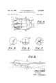
- FIG. 1 is a perspective view of one form of the grounded ship recovery apparatus.
- FIG. 2 is an end view showing one of the cylinders flooded and the blade embedded in the ocean bottom.
- FIG. 3 is an end view of the grounded ship recovery apparatus with both cylinders flooded and the ship pulled free.
- FIG. 4 is a top view of the preferred embodiment of the invention.
- FIGS. 5-6, and 7 are transverse sections along lines 5-5, 6-6, and 7-7 of FIG. 4.
- FIG. 8 is an end view of the preferred form of the invention in position and removing a grounded ship.
- a first embodiment of the grounded ship recovery apparatus 10 includes an elongate hollow cylinder 11 and an elongate hollow chamber 12 which is positioned in substantially parallel relationship to the cylinder by a pair of braces 13a, 13b.
- the chamber carries a longitudinally extending blade 14 which preferably forms a plane which diverges downwardly from a plane defined by the cylinder and the chamber.
- One or more lines or cables 15 are attached to the cylinder surface at one end and to the grounded ship at the other end.
- Both the cylinder and the chamber are provided with a plurality of inlet and outlet valves to permit selective flooding or evacuation of the cylinder and chamber.
- the flooding or evacuation operation can be effected by well known fluid control operations carried on the grounded ship recovery apparatus or by supporting vessel via a network of inlet and outlet hoses.
- the manner of construction of the apparatus that is, the physical dimensions and manner of joining elements, is in accordance with standard strength of materials critcria required for the task at hand. Constructing the apparatus of heavy-duty steel satisfactorily meets weight and strength requirements.
- a common characteristic of most beaches, banks, reefs, and similar underwater obstacles is that most are located at the top of a gradually rising submerged slope.
- the instant invention seeks to make use of this topographical feature, when the blade is embedded in the slope, to operate as a second class lever.
- the apparatus is positioned as shown in FIG. 1 with the chamber 12 disposed between the cylinder 11 and the grounded ship.
- the chamber is then flooded causing the chamber and blade 14 to sink.
- the flooded chamber and blade are of suflicient weight to force the blade into sediment which lies below the surface in many shallow water areas.
- the embedded blade becomes the fulcrum while the ship becomes the load.
- Flooding the cylinder creates a vertical force which is transmitted into a horizontal pulling force by pivoting about the embedded blade. This horizontal force is transferred to the grounded ship through the attached line to facilitate removal of the grounded ship.
- the apparatus is capable of exerting a horizontal force of great magnitude while using little complicated machinery.
- a horizontal pulling force of 13 /3 tons can be delivered to the grounded ship (assume that resistance to rotational movement by the blade is negligible).
- the flooding water can be evacuated from the cylinder and chamber to refloat the apparatus to enable transportation to a different location.
- a second and preferred embodiment of the grounded ship recovery apparatus utilizes a floatable hoisting apparatus 16 having a hollow water tight cylinder 17 in place of the elongate hollow cylinder 11.
- the cylinder is fully rotatable about a shaft 20 journaled at opposite ends in braces 13a, 13b.
- Water tight cylinder 17 is partitioned to provide a plurality of sump chambers 18 having sump drains 18a and a plurality of radially spaced water tight compartments 19, the latter being best shown in FIG. 7. Since each of the chambers 18 is identical and also since the compartments on either side of each chamber are alike, only one chamber and one plurality of spaced compartments are shown on the drawings, it being understood that several chambers and associated compartments are spaced within the cylinder.
- the fluid pressure supply in the form of a motor pump unit 21 pumps water from the chamber 18 to a selected ones of the radially spaced compartments 19 to impart a torque around the axis of the floating hoisting apparatus.
- Bi-directional rotation of the water-tight cylinder 17 is permissible by selective flooding of certain ones of the compartments 19.
- the preferred form of the invention is positioned and connected to the grounded ship with the blade embedded in a manner identical to that set out above. Selected ones of the compartments 19 are flooded to provide the correct amount of torque required to remove the grounded ship. Upon removing the grounded vessel, water is forced out of the floded chamber and the blade is removed from the sediment.
- An apparatus for removing a grounded ship comprising:
- a first floating means having a line attached to said grounded ship and being provided with a first flooding means permitting selective filling and evacuation for producing a force
- a second floating means having a blade formed to permit insertion in the ocean floor and being provided with a second flooding means for permitting selective filling and evacuation to insure said insertion;
- said first floating means is an elongate hollow cylinder
- said second floating means is an elongate hollow chamber with said blade longitudinally disposed;
- said means for interconnecting is a pair of braces, each having a first end pivotally attached to the cylinder on the cylinder axis and a second end aflixed to said chamber.
- said cylinder is a watertight hoisting apparatus having;
- a fluid pressure supply means for selectively delivering sump fluid to each of said compartments
- sump drain means communicating each compartment with said sump means
- said line is circumferentially wound on the exterior surface of said cylinder to transmit a horizontal pulling force to said grounded ship when simultaneous, selective flooding and evacuating of said com partments produces a rotational force.
Landscapes
- Engineering & Computer Science (AREA)
- Mechanical Engineering (AREA)
- Ocean & Marine Engineering (AREA)
- Cleaning Or Clearing Of The Surface Of Open Water (AREA)
Description
Sept. 24, 1968 E. N. ROSENBERG ETAL 3,402,688
GROUNDED SHIP RECOVERY APPARATUS Filed April 18. 1967 2 Sheets-Sheet 1 INVENTORB N EDGAR N. ROSENBERG 6 3 J /4 BY CHARLES s. MANN/N6 M ATTORNEYS Sept. 24, 1968 E. N. ROSENBERG ETAL 3,402,638
GROUNDED SHIP RECOVERY APPARATUS Filed April 18, 1967 2 Sheets-Sheet 2 2 FIG. 4 L
5064/? N. ROSENBERG CHARLES S. MANN/N6 T61 Ma 7 2. 424
H A TTOR/VEYS United States Patent 3 402,688 GRQUNDED SHIP itECOVERY APPARATUS Edgar N. Rosenberg, 6914 Mission Gorge Road 92120, and Charles S. Manning, 3454 Bangor Place 92106, both of San Diego, Calif.
Filed Apr. 18, 1967, Ser. No. 631,845 3 Claims. (Cl. 114-51) ABSTRACT OF THE DISiILOSURE The invention relates to a grounded ship recovery apparatus that includes two cylinders joined by a pair of braces. A blade mounted on the external surface of a first cylinder is inserted into the ocean floor between the other cylinder and a grounded ship to provide a pivot point. A line extending from the other cylinder to the ship transmits a horizontal pulling force to the ship when the first cylinder is flooded. A preferred embodiment of the invention utilizes a floatable hoist apparatus in place of the first cylinder. Rotational force provided by the floatable hoist apparatus is converted into a horizontal force for removing the grounded ship. When the ship has been pulled free, using apparatuses made in accordance with the two embodiments, water is pumped from the sunken cylinders to permit recovery of the entire apparatus.
The inventon described herein may be manufactured and used by or for the Government of the United States of America for governmental purposes without the payment of any royalties thereon or therefor.
Background of the invention The need for a device capable of exerting a powerful horizontal force to remove grounded ships is widespread since grounded ships are often abandoned on reefs and shores for want of a device capable of removing them. In many cases, tugboats, alone or in groups, simply cannot provide suflicient horizontal force.
It is a primary object of the invention to provide a grounded ship recovery apparatus capable of exerting horizontal forces greatly in excess of those forces produced by conventional means.
Another object of the invention is to provide a means by which the heavy lift capacity of a floatable hoist ap paratus can be converted to a horizontal force.
Still another object is to provide a grounded ship recovery apparatus which is mobile and completely recoverable.
Other objects and attended advantages wil become more apparent in the ensuing detailed description.
Summary of the invention Briefly, the invention is directed to provide a grounded ship recovery apparatus, utilizing a floatable hoist apparatus connected by braces to an elongate cylinder carrying a longitudinally extending blade. By flooding the cylinder the blade is embedded between the floatable hoist apparatus and the ship to provide a fulcrum or pivot point. A line extending from the floatable hoist apparatus is connected to the grounded ship. By selectively flooding and evacuating water tight compartments within the floatable hoist apparatus, a rotational force is transformed into a horizontal force through the line attached to the grounded ship. The invention provides a means for converting the great vertical-lift capacity of the floatable hoist apparatus to a horizontal force of equal magnitude. In this manner, horizontal forces, greatly in excess of those available by conventional means, are available to permit removal of grounded ships which otherwise had to be abandoned.
ice
Brief description of the drawings FIG. 1 is a perspective view of one form of the grounded ship recovery apparatus.
FIG. 2 is an end view showing one of the cylinders flooded and the blade embedded in the ocean bottom.
FIG. 3 is an end view of the grounded ship recovery apparatus with both cylinders flooded and the ship pulled free.
FIG. 4 is a top view of the preferred embodiment of the invention.
FIGS. 5-6, and 7 are transverse sections along lines 5-5, 6-6, and 7-7 of FIG. 4.
FIG. 8 is an end view of the preferred form of the invention in position and removing a grounded ship.
Description of the prefeflred embodimnets Referring now to FIG. 1, a first embodiment of the grounded ship recovery apparatus 10 includes an elongate hollow cylinder 11 and an elongate hollow chamber 12 which is positioned in substantially parallel relationship to the cylinder by a pair of braces 13a, 13b. The chamber carries a longitudinally extending blade 14 which preferably forms a plane which diverges downwardly from a plane defined by the cylinder and the chamber. One or more lines or cables 15 are attached to the cylinder surface at one end and to the grounded ship at the other end.
Both the cylinder and the chamber are provided with a plurality of inlet and outlet valves to permit selective flooding or evacuation of the cylinder and chamber. The flooding or evacuation operation can be effected by well known fluid control operations carried on the grounded ship recovery apparatus or by supporting vessel via a network of inlet and outlet hoses. Here it should be noted that the manner of construction of the apparatus, that is, the physical dimensions and manner of joining elements, is in accordance with standard strength of materials critcria required for the task at hand. Constructing the apparatus of heavy-duty steel satisfactorily meets weight and strength requirements.
A common characteristic of most beaches, banks, reefs, and similar underwater obstacles is that most are located at the top of a gradually rising submerged slope. The instant invention seeks to make use of this topographical feature, when the blade is embedded in the slope, to operate as a second class lever.
The apparatus is positioned as shown in FIG. 1 with the chamber 12 disposed between the cylinder 11 and the grounded ship. The chamber is then flooded causing the chamber and blade 14 to sink. The flooded chamber and blade are of suflicient weight to force the blade into sediment which lies below the surface in many shallow water areas. As seen in FIG. 2, the embedded blade becomes the fulcrum while the ship becomes the load. Flooding the cylinder creates a vertical force which is transmitted into a horizontal pulling force by pivoting about the embedded blade. This horizontal force is transferred to the grounded ship through the attached line to facilitate removal of the grounded ship.
The apparatus is capable of exerting a horizontal force of great magnitude while using little complicated machinery. By way of example, if the apparatus is operating in feet of water and the braces are feet long with the flooded cylinder weighing 10 tons, a horizontal pulling force of 13 /3 tons can be delivered to the grounded ship (assume that resistance to rotational movement by the blade is negligible). After both the chamber and the cylinder have been flooded and the grounded ship has been removed, the flooding water can be evacuated from the cylinder and chamber to refloat the apparatus to enable transportation to a different location.
A second and preferred embodiment of the grounded ship recovery apparatus utilizes a floatable hoisting apparatus 16 having a hollow water tight cylinder 17 in place of the elongate hollow cylinder 11. The cylinder is fully rotatable about a shaft 20 journaled at opposite ends in braces 13a, 13b. Water tight cylinder 17 is partitioned to provide a plurality of sump chambers 18 having sump drains 18a and a plurality of radially spaced water tight compartments 19, the latter being best shown in FIG. 7. Since each of the chambers 18 is identical and also since the compartments on either side of each chamber are alike, only one chamber and one plurality of spaced compartments are shown on the drawings, it being understood that several chambers and associated compartments are spaced within the cylinder. Depending from a shaft 20, the fluid pressure supply in the form of a motor pump unit 21 pumps water from the chamber 18 to a selected ones of the radially spaced compartments 19 to impart a torque around the axis of the floating hoisting apparatus. Bi-directional rotation of the water-tight cylinder 17 is permissible by selective flooding of certain ones of the compartments 19.
A further more detailed understanding of the operation of the water tight cylinder may be had by noting US. Patent No. 3,228,371 issued Jan. 11, 1966 to one of the present co-inventors, E. N. Rosenberg. The relative sizes, modes of operations and capabilties of this cylinder and lines disclosed in the cited patent are identical to that utilized in the present invention.
In operation, the preferred form of the invention is positioned and connected to the grounded ship with the blade embedded in a manner identical to that set out above. Selected ones of the compartments 19 are flooded to provide the correct amount of torque required to remove the grounded ship. Upon removing the grounded vessel, water is forced out of the floded chamber and the blade is removed from the sediment.
Obviously, many modifications and variations of the present invention are possible. In the light of the above teachings, it is therefore, to be understood that within the scope of the appended claims the invention may be practiced otherwise than as specifically described.
What is claimed is:
1. An apparatus for removing a grounded ship comprising:
a first floating means having a line attached to said grounded ship and being provided with a first flooding means permitting selective filling and evacuation for producing a force;
a second floating means having a blade formed to permit insertion in the ocean floor and being provided with a second flooding means for permitting selective filling and evacuation to insure said insertion; and
a means interconnecting said first and second floating means for insuring a conversion of said force to a horizontal force upon said insertion, thereby enabling the removal of said grounded ship.
2. An apparatus according to claim 1 in which:
said first floating means is an elongate hollow cylinder;
said second floating means is an elongate hollow chamber with said blade longitudinally disposed; and
said means for interconnecting is a pair of braces, each having a first end pivotally attached to the cylinder on the cylinder axis and a second end aflixed to said chamber.
3. An apparatus according to claim 2 in which:
said cylinder is a watertight hoisting apparatus having;
a plurality of internal walls partitioning the cylinder into a plurality of radially adjacent compartments,
afluid sump means,
a fluid pressure supply means for selectively delivering sump fluid to each of said compartments,
a sump drain means communicating each compartment with said sump means, and
said line is circumferentially wound on the exterior surface of said cylinder to transmit a horizontal pulling force to said grounded ship when simultaneous, selective flooding and evacuating of said com partments produces a rotational force.
References Cited UNITED STATES PATENTS 611,636 10/1898 Lake 114-51 1,081,103 12/1913 Ehinger 11452 1,201,337 10/1916 ONeal 114-51 MILTON BUCHLER, Primary Examiner.
TRYGVE M. BLIX, Examiner.
Priority Applications (1)
| Application Number | Priority Date | Filing Date | Title |
|---|---|---|---|
| US631845A US3402688A (en) | 1967-04-18 | 1967-04-18 | Grounded ship recovery apparatus |
Applications Claiming Priority (1)
| Application Number | Priority Date | Filing Date | Title |
|---|---|---|---|
| US631845A US3402688A (en) | 1967-04-18 | 1967-04-18 | Grounded ship recovery apparatus |
Publications (1)
| Publication Number | Publication Date |
|---|---|
| US3402688A true US3402688A (en) | 1968-09-24 |
Family
ID=24533010
Family Applications (1)
| Application Number | Title | Priority Date | Filing Date |
|---|---|---|---|
| US631845A Expired - Lifetime US3402688A (en) | 1967-04-18 | 1967-04-18 | Grounded ship recovery apparatus |
Country Status (1)
| Country | Link |
|---|---|
| US (1) | US3402688A (en) |
Cited By (2)
| Publication number | Priority date | Publication date | Assignee | Title |
|---|---|---|---|---|
| US3845634A (en) * | 1973-11-02 | 1974-11-05 | Us Navy | Dual hydro winch lift mechanism |
| US4442661A (en) * | 1982-08-30 | 1984-04-17 | Stuart Clifford H | Lawn mower pump |
Citations (3)
| Publication number | Priority date | Publication date | Assignee | Title |
|---|---|---|---|---|
| US611636A (en) * | 1898-10-04 | Apparatus for floating stranded vessels | ||
| US1081103A (en) * | 1912-03-28 | 1913-12-09 | Adolphe Ehinger | Buoyancy-tank. |
| US1201337A (en) * | 1915-09-28 | 1916-10-17 | Robert O'neal | Apparatus for raising submerged objects. |
-
1967
- 1967-04-18 US US631845A patent/US3402688A/en not_active Expired - Lifetime
Patent Citations (3)
| Publication number | Priority date | Publication date | Assignee | Title |
|---|---|---|---|---|
| US611636A (en) * | 1898-10-04 | Apparatus for floating stranded vessels | ||
| US1081103A (en) * | 1912-03-28 | 1913-12-09 | Adolphe Ehinger | Buoyancy-tank. |
| US1201337A (en) * | 1915-09-28 | 1916-10-17 | Robert O'neal | Apparatus for raising submerged objects. |
Cited By (2)
| Publication number | Priority date | Publication date | Assignee | Title |
|---|---|---|---|---|
| US3845634A (en) * | 1973-11-02 | 1974-11-05 | Us Navy | Dual hydro winch lift mechanism |
| US4442661A (en) * | 1982-08-30 | 1984-04-17 | Stuart Clifford H | Lawn mower pump |
Similar Documents
| Publication | Publication Date | Title |
|---|---|---|
| US3433024A (en) | Versatile marine structure | |
| US2551375A (en) | Submergible drilling barge and method of operation | |
| US3952527A (en) | Offshore platform for arctic environments | |
| WO2018074977A1 (en) | System and method for reconfiguring a mobile docking apparatus for transporting, removal, installation, housing and transferring assets | |
| RU2144611C1 (en) | Vessel for recovery or transportation of hydrocarbons from sea deposits and method for oil filling through loading hose | |
| US2602300A (en) | Apparatus for laying and retrieving pipe lines | |
| US3431879A (en) | Method and apparatus for offshore anchoring | |
| US4007700A (en) | Multiple seafloor storage and supply system | |
| US2699042A (en) | Portable marine foundation for drilling rigs and method of operation | |
| US4271550A (en) | Method for submerging an equipment of negative buoyancy | |
| US3434442A (en) | Offloading moored production storage unit | |
| US4168556A (en) | Roll and heave stabilized buoyant body | |
| US4973200A (en) | Method for manoeuvering a superstructure element relative to a fixed construction arranged in water, method for constructing a building structure and building structure constructed according to such a method | |
| US3479673A (en) | Apparatus and method for transporting fluids between a submerged storage tank and a floating vessel | |
| US3402688A (en) | Grounded ship recovery apparatus | |
| US3621662A (en) | Underwater storage structure and method of installation | |
| US2539695A (en) | Portable marine structure | |
| US3515084A (en) | Conversion of mat jack-up drill platforms to floating drill platforms | |
| US3740956A (en) | Portable retaining structure | |
| US4276846A (en) | Recovery apparatus | |
| US4107803A (en) | Sea terminal | |
| JPS5828157B2 (en) | single point floating mooring device | |
| US3395665A (en) | Deep water recovery | |
| Rankov | Slipping and launching | |
| CN215205302U (en) | A shipwreck salvage device |