US3402686A - Tufting machine - Google Patents
Tufting machine Download PDFInfo
- Publication number
- US3402686A US3402686A US667630A US66763067A US3402686A US 3402686 A US3402686 A US 3402686A US 667630 A US667630 A US 667630A US 66763067 A US66763067 A US 66763067A US 3402686 A US3402686 A US 3402686A
- Authority
- US
- United States
- Prior art keywords
- needles
- bars
- machine
- row
- pins
- Prior art date
- Legal status (The legal status is an assumption and is not a legal conclusion. Google has not performed a legal analysis and makes no representation as to the accuracy of the status listed.)
- Expired - Lifetime
Links
- 238000009732 tufting Methods 0.000 title description 9
- 239000004744 fabric Substances 0.000 description 10
- 230000007246 mechanism Effects 0.000 description 7
- 241000282472 Canis lupus familiaris Species 0.000 description 4
- 238000004519 manufacturing process Methods 0.000 description 4
- 230000005540 biological transmission Effects 0.000 description 3
- 210000000887 face Anatomy 0.000 description 2
- 239000004753 textile Substances 0.000 description 2
- 230000009471 action Effects 0.000 description 1
- 238000010276 construction Methods 0.000 description 1
- 239000000463 material Substances 0.000 description 1
- 238000000034 method Methods 0.000 description 1
- 230000004048 modification Effects 0.000 description 1
- 238000012986 modification Methods 0.000 description 1
- 230000003534 oscillatory effect Effects 0.000 description 1
- 230000000717 retained effect Effects 0.000 description 1
Images


Classifications
-
- D—TEXTILES; PAPER
- D05—SEWING; EMBROIDERING; TUFTING
- D05C—EMBROIDERING; TUFTING
- D05C15/00—Making pile fabrics or articles having similar surface features by inserting loops into a base material
- D05C15/04—Tufting
- D05C15/08—Tufting machines
- D05C15/10—Tufting machines operating with a plurality of needles, e.g. in one row
- D05C15/12—Tufting machines operating with a plurality of needles, e.g. in one row in more than one row
-
- D—TEXTILES; PAPER
- D05—SEWING; EMBROIDERING; TUFTING
- D05C—EMBROIDERING; TUFTING
- D05C15/00—Making pile fabrics or articles having similar surface features by inserting loops into a base material
- D05C15/04—Tufting
- D05C15/08—Tufting machines
- D05C15/16—Arrangements or devices for manipulating threads
- D05C15/20—Arrangements or devices, e.g. needles, for inserting loops; Driving mechanisms therefor
-
- D—TEXTILES; PAPER
- D05—SEWING; EMBROIDERING; TUFTING
- D05C—EMBROIDERING; TUFTING
- D05C15/00—Making pile fabrics or articles having similar surface features by inserting loops into a base material
- D05C15/04—Tufting
- D05C15/08—Tufting machines
- D05C15/16—Arrangements or devices for manipulating threads
- D05C15/22—Loop-catching arrangements, e.g. loopers; Driving mechanisms therefor
Definitions
- the present disclosure describes a tufting machine in which there are two rows of needles, each having separate control means, which control means will give a predetermined pattern of tufts during the tufting operation.
- the present invention relates to textiles and particularly to textile machines.
- chenille fabrics take the form of pile yarns which are connected with'a suitable backing. It is conventional to manufacture such fabrics by looping yarns through the backing after which the loops can be cut so as to form the pile. The needles which form the loops are controlled in such a way that the pile takes a predetermined pattern on the backing, and in this way the conventional chenille fabrics are formed.
- a first reciprocating means is connected to one of the rows of needles for reciprocating the latter and a second reciprocating means is connected to the other of the rows of needles for reciprocating the latter, and a first control means cooperates with the first reciprocating means for controlling the latter to reciprocate the selected needles of the first row while a second control means cooperates with the second reciprocating means for controlling the latter to reciprocate selected needles of the second row, so that in this way a predetermined pattern of loops can be achieved when the needles form loops in a well known manner through a suitable backing.
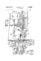
- FIG. 1 is a fragmentary top plan view showing that part of a machine which includes the structure of the present invention.
- FIG. 2 is an end view of the machine of FIG. 1 as seen from the right thereof.
- FIG. 3 is a transverse section of the machine of FIG. 1, taken along line 33 of FIG. 1 in the direction of the arrows and showing th estructure on a scale larger than that of FIG. 1.
- FIG. 4 shows the structure of FIG. 3 in a position of the parts different from that illustrated in FIG. 3.
- FIG. 5 is a fragmentary partly sectional elevation taken along line 5-5 of FIG. 3 in the direction of the arrows.
- FIG. 6 is a fragmentary sectional plan view taken along line 6-6 of FIG. 4 in the direction of the arrows and showing the structure on a scale larger than that of FIG. 4.
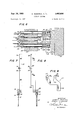
- FIG. 7 is a side elevation of one of the needle-carrying bars of the machine of the invention.
- FIG. 8 is a side elevation of another of the needlecarrying bars of the invention.
- FIG. 9 is a side elevation of one of the loopers which cooperates with aligned needles of the two rows.
- a belt 10 which delivers the drive to the machine of the invention from any suitable source such as a motor-driven pulley.
- the belt 10 drives a pulley 12 fixed to a rotary shaft 14 which drives a known mechanism Within a housing 16 which is supported on suitable standards so as to be situated at the porper elevation.
- the drive is transmitted by way of a belt 18 from a pulley 20 fixed to the shaft 14 to a second pulley 22 fixed to the shaft 24 so as to rotate the latter.
- This shaft 24 is supported for rotation by suitable bearings 26.
- the shaft 24 also fixedly carries a sprocket wheel 28 which serves to drive a chain 30.
- the chain 30 transmits the drive to a sprocket wheel 32 which is fixedly mounted on a shaft 34 also supported for rotation by suitable bearings, and the shaft 34 carries the patter-n drum 36 on which a selected series of earns 38 are fixed in a well known manner.
- the frame of the machine also carries a stationary horizontal shaft 40 on which a plurality of levers 42 are pivotally mounted in side by side relation, and the top ends of the levers 42 fixedly carry cam-follower fingers 44 respectively aligned with and cooperating with the earns 38 of the pattern drum 36.
- the levers 42 fixedly carry at their bottom ends a plurality of releasable fastening brackets 46 which respectively serve to connect to the levers 42 elongated connecting elements 43 in the form of suitable wires, for example.
- the plurality of elongated connecting elements 48 which are respectively connected at one end with the levers 42 are hooked at their other ends onto a plurality of elongated pins 50, respectively, as shown most clearly in FIG. 6.
- These pins 50 are carried by an elongated drive member 52 in the form of an elongated block formed with a row of horizontal bores 54 passing therethrough in the manner shown most clearly in FIG. 6.
- Each bore 54 carries a pair of bearings 56 in which a pin 50 is slidable, and a plurality of springs 58 (FIGS.
- the elongated drive member 52 is fixed with a plurality of rods 62 which extend through the housing 16 and which are acted upon by a known mechanism which functions during every operating cycle to lower and raise the rods 62 and the block 52 therewith, so that during each operating cycle the entire series of pins 50 is lowered together with the block 52.
- the pins 50 are arranged so as to form an upper row and a lower row, so that in this way the bores 54 can be staggered and spaced quite close to each other along the length of the machine.
- the bores 54 and the sleeves 56 were all located in a common plane, then in the horizontal plan of FIG. 6 the several pins 50 would have to be spread further apart from each other.
- the several pins 50 would have to be spread further apart from each other.
- each bar 66 carries at its lower end a needle-supporting bracket 68 fastened to the bar 66 by screws 70, and the bracket 68 of each bar 66 carries a pair of needles 72 releasably fastened to the bracket 68 by a screw 74, as is particularly apparent from FIG. 5. Therefore, the series of elongated bars 66 form a reciprocating means for reciprocating the row of needles 72 which are connected in pairs respectively to the bars 66.
- the several bars 66 respectively carry stop screws 76 which limit their upward movement in a manner described in greater detail below.
- the bars 66 are formed at their upper ends with suitable openings 78 for receiving the bottom ends of springs 80 which urge the bars 66 upwardly to predetermined starting positions.
- the lower row of pins 50 are respectively adapted to enter into a plurality of notches 82 which are re- 4 spectively formed in a plurality of elongated needlecarrying bars 84 which are situated beside and alternate with the bars 66.
- One of the bars 84 is shown in detail in FIG. 8.
- Each bar 84 carries as its lower end a needlesupporting bracket 86 fixed to the bar 84 by screws 88.
- Each bracket 86 carries a screw 90 for releasably fixing the bracket 86 and a pair of needles 92 which are respectively aligned with a pair of needles 72, so that in. this way two parallel rows of needles 72 and 92 are provided with the needles of one row respectively aligned with the needles of the other row.
- FIG. 5 shows the row of needles 72.
- Behind each of the needles 72 shown in FIG. 5 is a needle 92, so that with the machine of the invention it is possible to situate a large number of needles in the small space.
- the several bars 84 form a reciprocating means for reciprocating the row of needles 92. These bars 84 are of course wider than the bars 66, as is apparent from a comparison of FIGS. 7 and 8.
- the bars 84 have left end faces, as viewed in FIG. 6, which are situated in a plane common with the left end faces of the bars 66 of FIG. 6, so that all of the bars have outer rear faces located in a common plane, and it is the wider bars 84 which extend forwardly beyond the narrower bars 66.
- the bars 84 carry a plurality of stop screws 94 which are adapted to cooperate with a stop member which extends across all of the bars in a manner described below.
- the bars 84 are formed at their upper ends with openings 96 for receiving the bottom ends of springs 80 which also serve to yieldably maintain the bars 84 in upper starting positions.
- each of the brackets 68 extends to the left beyond the bar 66 on which it is mounted into overlapping relation with the adjoining bar 84, and for this purpose the lower rear end portion of each bar 84 is formed with a notch 98 (FIG. 8) for receiving the bracket 68-.
- the several brackets 68 can be located quite close to each other so as to be able to carry a pair of pins spaced from each other by a distance greater than the thickness of the bar 66.
- each bar 84 carries at its front face the bracket 86 which extends beyond the bar 84 into overlapping relation with the next bar 66.
- each bracket 68 extends from the bar 66 on which it is mounted to the left into the notch 98 of the next bar 84
- each bracket 86 extends from the front face of the bar 84, on which it is mounted to the right, as viewed in FIG. 5, into overlapping relation with the adjoining bar 66.
- an elongated housing 100 is situated in front of the housing 16 for the drive mechanism, and it is this housing 100 which accommodates the structure which carries the bars 66 and 84.
- This frame structure includes, within the housing 100, a front support 102 maintained stationary in any suitable way and carrying an elongated support member 104 of channelshaped configuration having upper and lower rearwardly directed ribs 106.
- These ribs carry a series of rearwardly directed plates 108 which are relatively thin and which define between themselves the spaces in which the several bars 84 and 66 are guided for sliding vertical movement.
- the plates 108 are quite thin and serve to slidably guide the several needle-carrying bars 66 and 84 for vertical reciprocating movement.
- Each of the ribs 106 fixedly carries a series of plates 108 which are fixed to the ribs 106 in any suitable manner.
- the lower rib 106 in addition has at its outer ends a pair of plates to which a lower guide bar 111 is fixed for engaging the rear faces of all of the reciprocating needle-carrying bars 66 and 84, and the upper rib in the same way carries a rear plate 112.
- the rear plate 112 extends across and then slidably engages all of the bars 66 and 84 at their rear outer faces. It is the lower edge of the bar 112 which forms a stop edge forthe several stop screws 76 and 94, as is particularly apparent from FIG. 3.
- the frame member 102 fixedly carries, as indicated in FIG. 4, a plurality of stop members 114 fixed in position by a plurality of set screws 116 and engaging the top ends of the bars when they are in their upper initial positions, as shown in FIG. 3.
- Yarn guide 118 are mounted alongside the housing 16, as indicated in FIG. 2, and the structure which carries the guides 118 also carries conventional yarn tensioners 120 which serve to tension the several yarns 122 which pass through the rear row of needles 72.
- the machine also has a series of yarns 124 which are guided through any suitable eyes or the like so as to pass through the yarn tensioners 126 into the eyes of the needles 92, as shown most clearly in FIGS. 3 and 4.
- These several yarn tensioners 126 are directly carried by the brackets 86 and include springy plates 128 which engage and press against the yarns 124, respectively, so as to tension the latter.
- a pair of yarns 124 cooperate with each tensioner 126 before passing through the pair of needles 92 carried by the bracket 86.
- a pair of yarns 122 are acted upon by a pair of tensioners 120 before reaching the pair of needles 72 carried by each bracket 68.
- the frame member 104 carries a pair of yarn-guiding tubes 130 situated behind each bar 66 and serving to guide the pair of yarns 122 downwardly to the pair of needles 72 carried by each bracket 68.
- the several needles 72 and 92 are reciprocated through any suitable backing such as the layer of fabric 132 indicated in FIGS. 3 and 4.
- This backing layer is acted upon in a known way by a presser foot assembly 134, and a feed dog mechanism 136 is provided for feeding the backing material 132 also in a known way.
- Beneath the bed 138 of the machine is situated the several transmissions which are acted upon by the drive mechanism within the housing 16.
- These transmissions include, for example, the bar 140 which is vertically reciprocated and serves to oscillate a shaft 142 back and forth about is axis.
- This shaft is fixed to levers 144 which are in turn linked to the structure which carries the feed dog mechanism 136 whose movement is controlled not only by the levers 144 but also by the levers 148 which are mounted for rocking movement on a shaft 150, so that in this way the dogs will carry out the necessary up and down as well as forward and reverse movement, as well known in theart.
- each needle 92 of the front row is a needle 72 of the back row, so that in this way the two rows of needles have aligned pairs of needles one of which is situated in front of the other, and with each pair of these front and rear aligned needles is associated a looper 152, one of which is shown in FIG. 9.
- Each looper is in the form of a plate 154 having at its upper end a pair of looping portions 156 which respectively cooperate with the forwardly and rearwardly aligned pair of needles, and at its front end-each looper 152 has a depending lug 158 by which it is mounted on a block 160.
- This block 160 is carried by a rod 162 received in notches formed in levers 164 which are clamped onto an oscillatory shaft 166 which is oscillated back and forth about its axis by a lever 168 also fixed to the shaft 166 which is supported for rotation about its axis in any suitable bearings.
- Lever 168 is formed with a slot in which is received a pin connected to a reciprocating bar 170 which is reciprocated by the mechanism in the housing 16 in a manner well known in the art, so that in this way the loopers 52 all move through endless paths during each cycle enabling the looping portions 156 to enter into a loop formed by a needle during its downward movement and to hold onto this loop as the needle moves back up through the backing 132. In this way successive loops are formed and held by the loopers .152.
- each pair of knives is mounted in a block 174 carried by a shaft 176 to which a lever 178 is clamped.
- the lever 178 is pivotally connected to a link 180 which is in turn pivotally connected to a second lever 182 clamped onto the shaft 166, so that as the shaft 166 is oscillated about its axis during reciprocation of the bar 170 in the manner described above, not only do the loopers 152 move through endless paths, but in addition the knives 172 are actuated so as to slide with respect to the loopers.
- These knives have upper cutting edges which serve to slice through the lower ends of the loops so as to form separate pile yarns therefrom, as is apparent from FIGS. 3 and 4.
- Each connecting element 48 can be adjusted by a turnbuckle 49, as diagrammatically indicated in FIGS. 3 and 4.
- a first row of needles for passing through the backing to loop yarns thereon, a second row of needles parallel and adjacent to said first row also for looping yarns onto the backing, said first and second rows of needles being one behind the other in the direction of travel of said backing, first and second vertically elongated axially reciprocating means respectively connected operatively to said first and second rows of needles for reciprocating the latter, said first and second reciprocating means having rear outer faces located in a common vertical plane, and separate unconnected first and second control means respectively being directly connected into said outer faces of said first and second reciprocating means for controlling the latter to provide a predetermined sequence of operation of selected needles which will provide a given pattern of yarn attached by said needles to the backing said first and second control means driving said first and second reciprocating means, respectively.
- said reciprocating means including a plurality of driven members respectively connected operatively to said needles of said first and second rows for driving said needles, and a plurality of driving members respectively provided for said driven members for driving the latter, said control means being operatively connected with said driving and driven members to control the connection therebetween, said control means maintaining a connection between driving members and those driven members which are connected with needles which are to be actuated and eliminating a connection between those driving members and their cooperating driven members whose needles are not to be reciprocated, so as to achieve a predetermined pattern.
- driven members respectively being in the form of elongated bars respectively carrying said needles, and guide means guidin-g said bars for longitudinal movement.
- spring means operatively connected to said bars for yieldablymaintaining the latter at predetermined starting positions so that where pins are not situated in notches of selected bars, the latter selected bars will be maintained by said spring means in their starting positions to prevent operation of the needles connected therewith.
- said control means including a pattern drum respectively having a row of cams arranged with every'other one of said cams corresponding to one row of needles and the other alternating cams situated between every other one 'of said cams corresponding to the other row of needles, a'plurality of levers turnable about a common axis and respectively having cam-follower fingers engaging said cams, spring means operatively connected to said pins for urging the latter into said notches, and connecting elements respectively connecting said levers to said pins for pulling the latter out of said notches in opposition to the spring means acting upon said pins when raised portions of said cams engage said fingers to turn said levers.
- said reciprocating means including a plurality of bars respectively carr'ying said needles, and the needles of one row being aligned with the needles of the other row.
- said reciprocating means including a plurality of elongated bars, and each bar carrying a pair of needles so that in each row each successive pair of needles are respectively carried by individual bars.
Landscapes
- Engineering & Computer Science (AREA)
- Chemical & Material Sciences (AREA)
- Materials Engineering (AREA)
- Textile Engineering (AREA)
- Treatment Of Fiber Materials (AREA)
Description
M.RODSTEIN ET AL 3,402,686
Sept. 24, 1968 TUFT ING MACHINE 6 Sheets-Sheet 1 Filed Sept. 11, 1967 v, Sww m? Ts HZ m 3 2 K a Z l MN m H 6% H M. Q m m Sept. 24, 1968 RODSTEIN ET AL 3,402,686
TUFTING MACHINE Filed Sept. 11, 1967' 6 Sheets$heet 2 6 Sheets-Sheet 5 M. RODSTEIN ET AL TUFTING MACHINE Sept. 24, 1968 Filed Sept. 11, 1967 Sept. 24, 1968 o s-r m ET AL 3,402,686
TUFTING MACHINE 6 Sheets-Sheet 4 Filed Sept. 11, 1967 v frvn lll l I Sept. 24, 1968 RODSTElN ET AL 3,402,686
TUFT ING MACHINE Filed Sept. 11, 1967 6 Sheets-Sheet 5 (ral U! INVENTORS Sept. 24, 1968 s m ET AL 3,402,686
TUFTING MACHINE Filed Sept. 11, 1967 6 Sheets-Sheet 6 F/G 7 FIG. 8
447 TOR/V15 Y United States Patent V ABSTRACT OF THE DISCLOSURE The present disclosure describes a tufting machine in which there are two rows of needles, each having separate control means, which control means will give a predetermined pattern of tufts during the tufting operation.
Description of the invention The present invention relates to textiles and particularly to textile machines.
The invention deals in particular with machines which are adapted to form chenille fabrics. As is well known, chenille fabrics take the form of pile yarns which are connected with'a suitable backing. It is conventional to manufacture such fabrics by looping yarns through the backing after which the loops can be cut so as to form the pile. The needles which form the loops are controlled in such a way that the pile takes a predetermined pattern on the backing, and in this way the conventional chenille fabrics are formed.
Although machines are known at the present time for providing fabrics of the above type, these known machines have several drawbacks. For example, the patterns which can be achieved are relatively coarse because of the limitations with respect to the spacing of the needles which form the loops. Thus, at the present time it is not possible to locate the loop-forming needles very close to each other so that as a result only relatively coarse chenille patterns can be achieved.
It is accordingly a primary object of the present invention to provide a machine capable of manufacturing chenille fabrics in such a way that they can be provided with any desired pattern which has in it a far finer degree of detailing than has heretofore been possible.
In particular, it is an object of the invention to provide a machine of the above type which can have the needles thereof located in far closer proximity than has heretofore been possible.
In particular, it is an object of the invention to provide a machine of the above type with a plurality of rows of needles wherein the needles of the individual rows can be precisely controlled to provide a selected pattern even though the needles of each row are located in close proximity to each other and the two rows of needles are also located in close proximity to each other.
Furthermore, it is an object of the invention to provide a machine of the above type which can have all of the needles controlled from a single pattern drum as a result of a novel transmission of the invention between the pattern drum and the needle-carrying bars.
Moreover, it is an object of the invention to provide a. machine which while capable of accomplishing the above objects nevertheless is composed of relatively simple rugged elements which operate very reliably.
Furthermore, it is an object of the invention to provide a machine of the above type which can be very easily controlled by persons skilled in the art without requiring the operator of the machine to learn new techniques, so that an experienced operator of a known chenille manufacturing machine can operate the machine of the invention without any difficulty.
Ice
Still further objects and advantages will appear in the more detailed description set forth below, it being understood, however, that this more detailed description is given 'by way of illustration and explanation only and not by way of limitation, since various changes therein may be made by those skilled in the art without departing from the scope and spirit of the present invention.
Primarily, with the machine of the invention there is provided a pair of elongated rows of needles which are located in close proximity to each other and which has the two rows of needles also located in close proximity to each other.
A first reciprocating means is connected to one of the rows of needles for reciprocating the latter and a second reciprocating means is connected to the other of the rows of needles for reciprocating the latter, and a first control means cooperates with the first reciprocating means for controlling the latter to reciprocate the selected needles of the first row while a second control means cooperates with the second reciprocating means for controlling the latter to reciprocate selected needles of the second row, so that in this way a predetermined pattern of loops can be achieved when the needles form loops in a well known manner through a suitable backing.
Brief description of drawings With the foregoing and other objects in view, the invention consists of the novel construction, combination and arrangement of parts as hereinafter more specifically described, and illustrated in the accompanying drawings, wherein is shown an embodiment of the invention, but it is to be understood that changes, variations and modifications can be resorted to which fall within the scope of the claims hereunto appended.
In the drawings wherein like reference characters denote corresponding parts throughout the several views:
FIG. 1 is a fragmentary top plan view showing that part of a machine which includes the structure of the present invention.
FIG. 2 is an end view of the machine of FIG. 1 as seen from the right thereof.
FIG. 3 is a transverse section of the machine of FIG. 1, taken along line 33 of FIG. 1 in the direction of the arrows and showing th estructure on a scale larger than that of FIG. 1.
FIG. 4 shows the structure of FIG. 3 in a position of the parts different from that illustrated in FIG. 3.
FIG. 5 is a fragmentary partly sectional elevation taken along line 5-5 of FIG. 3 in the direction of the arrows.
FIG. 6 is a fragmentary sectional plan view taken along line 6-6 of FIG. 4 in the direction of the arrows and showing the structure on a scale larger than that of FIG. 4.
FIG. 7 is a side elevation of one of the needle-carrying bars of the machine of the invention.
FIG. 8 is a side elevation of another of the needlecarrying bars of the invention.
FIG. 9 is a side elevation of one of the loopers which cooperates with aligned needles of the two rows.
Referring now to FIG. 1, there is fragmentarily illustrated therein a belt 10 which delivers the drive to the machine of the invention from any suitable source such as a motor-driven pulley. The belt 10 drives a pulley 12 fixed to a rotary shaft 14 which drives a known mechanism Within a housing 16 which is supported on suitable standards so as to be situated at the porper elevation. In addition, the drive is transmitted by way of a belt 18 from a pulley 20 fixed to the shaft 14 to a second pulley 22 fixed to the shaft 24 so as to rotate the latter. This shaft 24 is supported for rotation by suitable bearings 26.
As is shown most clearly in FIG. 2, the shaft 24 also fixedly carries a sprocket wheel 28 which serves to drive a chain 30. The chain 30 transmits the drive to a sprocket wheel 32 which is fixedly mounted on a shaft 34 also supported for rotation by suitable bearings, and the shaft 34 carries the patter-n drum 36 on which a selected series of earns 38 are fixed in a well known manner.
The frame of the machine also carries a stationary horizontal shaft 40 on which a plurality of levers 42 are pivotally mounted in side by side relation, and the top ends of the levers 42 fixedly carry cam-follower fingers 44 respectively aligned with and cooperating with the earns 38 of the pattern drum 36.
The levers 42 fixedly carry at their bottom ends a plurality of releasable fastening brackets 46 which respectively serve to connect to the levers 42 elongated connecting elements 43 in the form of suitable wires, for example.
The plurality of elongated connecting elements 48 which are respectively connected at one end with the levers 42 are hooked at their other ends onto a plurality of elongated pins 50, respectively, as shown most clearly in FIG. 6. These pins 50 are carried by an elongated drive member 52 in the form of an elongated block formed with a row of horizontal bores 54 passing therethrough in the manner shown most clearly in FIG. 6. Each bore 54 carries a pair of bearings 56 in which a pin 50 is slidable, and a plurality of springs 58 (FIGS. 3 and 4) are respectively connected at one end to the pins 50 and at their opposite end to stationary members 60 which fasten the springs to the drive member 52, so that in this way the springs 58 form a spring means urging the pins 50 to the right, as viewed in FIG. 6. The elongated drive member 52 is fixed with a plurality of rods 62 which extend through the housing 16 and which are acted upon by a known mechanism which functions during every operating cycle to lower and raise the rods 62 and the block 52 therewith, so that during each operating cycle the entire series of pins 50 is lowered together with the block 52.
As is apparent from FIGS. 3 and 6, the pins 50 are arranged so as to form an upper row and a lower row, so that in this way the bores 54 can be staggered and spaced quite close to each other along the length of the machine. In other words if the bores 54 and the sleeves 56 were all located in a common plane, then in the horizontal plan of FIG. 6 the several pins 50 would have to be spread further apart from each other. However, by
staggering the successive bores it is possible to locate the pins within a space whose dimension in a direction perpendicularly of the pins is much less than would be required if all of the pins were in a common plane. Of course, all of the pins are slidably mounted for longitudinal reciprocating movement, in the manner shown in FIG. 6.
The upper row of pins 50 shown in FIG. 6 are respectively adapted to enter into notches 64 respectively formed in elongated driven members 66 in the form of elongated and needle-carrying bars one of which is shown in detail in FIG. 7. Thus, as may be seen from FIG. 7 each bar 66 carries at its lower end a needle-supporting bracket 68 fastened to the bar 66 by screws 70, and the bracket 68 of each bar 66 carries a pair of needles 72 releasably fastened to the bracket 68 by a screw 74, as is particularly apparent from FIG. 5. Therefore, the series of elongated bars 66 form a reciprocating means for reciprocating the row of needles 72 which are connected in pairs respectively to the bars 66.
The several bars 66 respectively carry stop screws 76 which limit their upward movement in a manner described in greater detail below. In addition, the bars 66 are formed at their upper ends with suitable openings 78 for receiving the bottom ends of springs 80 which urge the bars 66 upwardly to predetermined starting positions.
The lower row of pins 50 are respectively adapted to enter into a plurality of notches 82 which are re- 4 spectively formed in a plurality of elongated needlecarrying bars 84 which are situated beside and alternate with the bars 66. One of the bars 84 is shown in detail in FIG. 8. Each bar 84 carries as its lower end a needlesupporting bracket 86 fixed to the bar 84 by screws 88. Each bracket 86 carries a screw 90 for releasably fixing the bracket 86 and a pair of needles 92 which are respectively aligned with a pair of needles 72, so that in. this way two parallel rows of needles 72 and 92 are provided with the needles of one row respectively aligned with the needles of the other row. The needles of each row are located quite close to each other, as is apparent from FIG. 5 which shows the row of needles 72. Behind each of the needles 72 shown in FIG. 5 is a needle 92, so that with the machine of the invention it is possible to situate a large number of needles in the small space. The several bars 84 form a reciprocating means for reciprocating the row of needles 92. These bars 84 are of course wider than the bars 66, as is apparent from a comparison of FIGS. 7 and 8.
The bars 84 have left end faces, as viewed in FIG. 6, which are situated in a plane common with the left end faces of the bars 66 of FIG. 6, so that all of the bars have outer rear faces located in a common plane, and it is the wider bars 84 which extend forwardly beyond the narrower bars 66. The bars 84 carry a plurality of stop screws 94 which are adapted to cooperate with a stop member which extends across all of the bars in a manner described below. In addition the bars 84 are formed at their upper ends with openings 96 for receiving the bottom ends of springs 80 which also serve to yieldably maintain the bars 84 in upper starting positions.
As is particularly apparent from FIG. 5, each of the brackets 68 extends to the left beyond the bar 66 on which it is mounted into overlapping relation with the adjoining bar 84, and for this purpose the lower rear end portion of each bar 84 is formed with a notch 98 (FIG. 8) for receiving the bracket 68-. In this way the several brackets 68 can be located quite close to each other so as to be able to carry a pair of pins spaced from each other by a distance greater than the thickness of the bar 66. In the same way, each bar 84 carries at its front face the bracket 86 which extends beyond the bar 84 into overlapping relation with the next bar 66.
Thus, as viewed in FIG. 5, while each bracket 68 extends from the bar 66 on which it is mounted to the left into the notch 98 of the next bar 84, each bracket 86 extends from the front face of the bar 84, on which it is mounted to the right, as viewed in FIG. 5, into overlapping relation with the adjoining bar 66.
As is apparent from FIG. 2, an elongated housing 100 is situated in front of the housing 16 for the drive mechanism, and it is this housing 100 which accommodates the structure which carries the bars 66 and 84. This frame structure includes, within the housing 100, a front support 102 maintained stationary in any suitable way and carrying an elongated support member 104 of channelshaped configuration having upper and lower rearwardly directed ribs 106. These ribs carry a series of rearwardly directed plates 108 which are relatively thin and which define between themselves the spaces in which the several bars 84 and 66 are guided for sliding vertical movement. Thus, the plates 108 are quite thin and serve to slidably guide the several needle-carrying bars 66 and 84 for vertical reciprocating movement. Each of the ribs 106 fixedly carries a series of plates 108 which are fixed to the ribs 106 in any suitable manner. The lower rib 106 in addition has at its outer ends a pair of plates to which a lower guide bar 111 is fixed for engaging the rear faces of all of the reciprocating needle-carrying bars 66 and 84, and the upper rib in the same way carries a rear plate 112.
The rear plate 112 extends across and then slidably engages all of the bars 66 and 84 at their rear outer faces. It is the lower edge of the bar 112 which forms a stop edge forthe several stop screws 76 and 94, as is particularly apparent from FIG. 3.
In addition to the stop formed by cooperation of the bar 112 with the various screws 76 and 94, the frame member 102 fixedly carries, as indicated in FIG. 4, a plurality of stop members 114 fixed in position by a plurality of set screws 116 and engaging the top ends of the bars when they are in their upper initial positions, as shown in FIG. 3.
As is shown most clearly in FIGS. 3 and 4, the frame member 104 carries a pair of yarn-guiding tubes 130 situated behind each bar 66 and serving to guide the pair of yarns 122 downwardly to the pair of needles 72 carried by each bracket 68.
In order to form a chenille pattern 'the several needles 72 and 92 are reciprocated through any suitable backing such as the layer of fabric 132 indicated in FIGS. 3 and 4. This backing layer is acted upon in a known way by a presser foot assembly 134, and a feed dog mechanism 136 is provided for feeding the backing material 132 also in a known way. Beneath the bed 138 of the machine is situated the several transmissions which are acted upon by the drive mechanism within the housing 16. These transmissions include, for example, the bar 140 which is vertically reciprocated and serves to oscillate a shaft 142 back and forth about is axis. This shaft is fixed to levers 144 which are in turn linked to the structure which carries the feed dog mechanism 136 whose movement is controlled not only by the levers 144 but also by the levers 148 which are mounted for rocking movement on a shaft 150, so that in this way the dogs will carry out the necessary up and down as well as forward and reverse movement, as well known in theart.
As was indicated above, situated behind each needle 92 of the front row is a needle 72 of the back row, so that in this way the two rows of needles have aligned pairs of needles one of which is situated in front of the other, and with each pair of these front and rear aligned needles is associated a looper 152, one of which is shown in FIG. 9. Each looper is in the form of a plate 154 having at its upper end a pair of looping portions 156 which respectively cooperate with the forwardly and rearwardly aligned pair of needles, and at its front end-each looper 152 has a depending lug 158 by which it is mounted on a block 160. This block 160 is carried by a rod 162 received in notches formed in levers 164 which are clamped onto an oscillatory shaft 166 which is oscillated back and forth about its axis by a lever 168 also fixed to the shaft 166 which is supported for rotation about its axis in any suitable bearings. Lever 168 is formed with a slot in which is received a pin connected to a reciprocating bar 170 which is reciprocated by the mechanism in the housing 16 in a manner well known in the art, so that in this way the loopers 52 all move through endless paths during each cycle enabling the looping portions 156 to enter into a loop formed by a needle during its downward movement and to hold onto this loop as the needle moves back up through the backing 132. In this way successive loops are formed and held by the loopers .152. I
Situated beside and slidably engaging the loopers 152 are pairs of knives 172. Each pair of knives is mounted in a block 174 carried by a shaft 176 to which a lever 178 is clamped. The lever 178 is pivotally connected to a link 180 which is in turn pivotally connected to a second lever 182 clamped onto the shaft 166, so that as the shaft 166 is oscillated about its axis during reciprocation of the bar 170 in the manner described above, not only do the loopers 152 move through endless paths, but in addition the knives 172 are actuated so as to slide with respect to the loopers. These knives have upper cutting edges which serve to slice through the lower ends of the loops so as to form separate pile yarns therefrom, as is apparent from FIGS. 3 and 4.
The manner in which the above-described structure operates is believed to be clear. During each operating cycle the feed dogs will feed the backing 132 by a suitable increment and selected needles will be reciprocated downwardly through and back up out of the backing 132,
forming beneath the backing loops which are engaged by the looping portions 156 of the loopers 152. These retained loops are subsequently severed by the knives 172.
Moreover, not all of the needles 72 and 92 will pass downwardly through the fabric backing. The combination of pattern earns 38 by the pattern drum 36 will determine which needles are actuated during one revolution of the drum 36. During this one revolution of the drum the needles will of course be reciprocated through a relatively large number of operating cycles.
In this way it is possible to achieve during each revolution of the pattern drum a predetermined pattern of the pile which forms the chenille, and this pattern will of course repeat itself during the successive revolutions of the pattern drum.
Of course, during each operating cycle the needles which are automatically selected by the cams of the pattern drum will be lowered and raised. This action is brought about by the lowering and raising of the block or drive member 52 at each operating cycle as was pointed out above. Those needles which are not to be reciprocated during a given operating cycle will have their pins 50 drawn out of their notches because at this time raised portions of the pattern cams will engage the fingers of the levers 42 turning the latter in a clockwise direction, as viewed in FIGS. 2-4, so as to withdraw from the notches of the needle-car-rying bars those pins which are connected with levers which have been turned by en-- gagement of the cam follower fingers with raised portions of the cams. Therefore, only those pins 50 which can be maintained by the springs 58 in notches of the needlecarrying bars will transmit the vertical movement of the drive member 52 to the driven members which are formed by the needle-carrying bars 66 and 84. Therefore the spring means formed by the springs will maintain in a raised initial position those bars 66 and 84 whose pins 50 have been pulled out of their notches by the cams of the pattern drum, and in this way it is only preselected needles which will move down through the fabric. Of course these needles will move up and down in pairs, and separate pairs of yarns are provided for the pairs of needles respectively connected to the several bars 66 and 84.
Because of the arrangement of the bars and needlecarrying structure of the invention, it is possible to achieve with the structure of the invention a very fine detail in the pattern which heretofore could not be achieved. This result is brought about by the abovedescribed arrangement according to which the two rows of needles are actuated by two sets of bars 66 and 84 which while they alternate with each other nevertheless are capable of carrying the brackets 6-8 and 86 which can arrange the needles in pairs quite close to each other in each row.
Each connecting element 48 can be adjusted by a turnbuckle 49, as diagrammatically indicated in FIGS. 3 and 4.
As many changes could be made in the above tufting machine, and many widely different embodiments of this invention could be made without departure from the scope of the claims, it is intended that all matter contained in the above description shall be interpreted 'as illustrative and not in a limiting sense.
Having now particularly described and ascertained the nature of the invention, and in what manner the same is to be performed, what is claimed is:
1. In a chenille fabric manufacturing machine in which chenille patterns are rformed on a suitable backing, a first row of needles for passing through the backing to loop yarns thereon, a second row of needles parallel and adjacent to said first row also for looping yarns onto the backing, said first and second rows of needles being one behind the other in the direction of travel of said backing, first and second vertically elongated axially reciprocating means respectively connected operatively to said first and second rows of needles for reciprocating the latter, said first and second reciprocating means having rear outer faces located in a common vertical plane, and separate unconnected first and second control means respectively being directly connected into said outer faces of said first and second reciprocating means for controlling the latter to provide a predetermined sequence of operation of selected needles which will provide a given pattern of yarn attached by said needles to the backing said first and second control means driving said first and second reciprocating means, respectively.
2. In a machine as recited in claim 1, said reciprocating means including a plurality of driven members respectively connected operatively to said needles of said first and second rows for driving said needles, and a plurality of driving members respectively provided for said driven members for driving the latter, said control means being operatively connected with said driving and driven members to control the connection therebetween, said control means maintaining a connection between driving members and those driven members which are connected with needles which are to be actuated and eliminating a connection between those driving members and their cooperating driven members whose needles are not to be reciprocated, so as to achieve a predetermined pattern.
3. In a machine as recited in claim 2, said driven members respectively being in the form of elongated bars respectively carrying said needles, and guide means guidin-g said bars for longitudinal movement.
4. In a machine as recited in claim 3, the bars which are operatively connected with the needles of one of said rows, respectively, respectively alternating with and situated beside the bars which are respectively connected to the needles of the other-of said rows.
5. In a machine as recited in claim 3, all of said bars :18 respectively h'a'ving outer faces respectively formed with notches, a driving member mounted for reciprocation longitudinally of said driven members, and a plurality'of motion-transmitting pins 'respectively'cariie'd slidably by said driving member and respectively received in said notches for connecting said driven members'to said driving member for movement therewith, said control means acting on said pins to 'respectively'inaintain them in said notches or to remove selected pins from their notches.
6. In a machine'as recited in c'laimS, spring means operatively connected to said bars for yieldablymaintaining the latter at predetermined starting positions so that where pins are not situated in notches of selected bars, the latter selected bars will be maintained by said spring means in their starting positions to prevent operation of the needles connected therewith.
7. In a machine as recited in claim 5, said control means including a pattern drum respectively having a row of cams arranged with every'other one of said cams corresponding to one row of needles and the other alternating cams situated between every other one 'of said cams corresponding to the other row of needles, a'plurality of levers turnable about a common axis and respectively having cam-follower fingers engaging said cams, spring means operatively connected to said pins for urging the latter into said notches, and connecting elements respectively connecting said levers to said pins for pulling the latter out of said notches in opposition to the spring means acting upon said pins when raised portions of said cams engage said fingers to turn said levers.
8. In a machine as recited in claim 1, said reciprocating means including a plurality of bars respectively carr'ying said needles, and the needles of one row being aligned with the needles of the other row.
9. In a machine as recited in claim 8, the bars which carry the needle of one of said rows respectively alternating with the bars which carry the needles of the other of said rows.
10. In a machine as recited in claim 1, said reciprocating means including a plurality of elongated bars, and each bar carrying a pair of needles so that in each row each successive pair of needles are respectively carried by individual bars.
References Cited UNITED STATES PATENTS 2,989,014 6/1961 Dedmon ll279 3,056,364 10/ 1962 Dedmon ll279 3,160,125 12/1964 Bryant et al. ll279 3,172,380 3/1965 Boyles ll279 3,259,088 7/1966 Rockholt l12-'79 HERBERT F. ROSS, Primary Examiner.
Priority Applications (1)
| Application Number | Priority Date | Filing Date | Title |
|---|---|---|---|
| US667630A US3402686A (en) | 1967-09-11 | 1967-09-11 | Tufting machine |
Applications Claiming Priority (1)
| Application Number | Priority Date | Filing Date | Title |
|---|---|---|---|
| US667630A US3402686A (en) | 1967-09-11 | 1967-09-11 | Tufting machine |
Publications (1)
| Publication Number | Publication Date |
|---|---|
| US3402686A true US3402686A (en) | 1968-09-24 |
Family
ID=24678971
Family Applications (1)
| Application Number | Title | Priority Date | Filing Date |
|---|---|---|---|
| US667630A Expired - Lifetime US3402686A (en) | 1967-09-11 | 1967-09-11 | Tufting machine |
Country Status (1)
| Country | Link |
|---|---|
| US (1) | US3402686A (en) |
Cited By (10)
| Publication number | Priority date | Publication date | Assignee | Title |
|---|---|---|---|---|
| US3633523A (en) * | 1970-10-29 | 1972-01-11 | Card & Co Inc | Tufting machine having multiple stroke needle bars |
| US3635177A (en) * | 1970-09-22 | 1972-01-18 | Card & Co Inc | Narrow gauge hook bar for tufting machine |
| US3776163A (en) * | 1972-10-02 | 1973-12-04 | Bigelow Sanford Inc | Method of changing yarn supply in a tufting machine |
| US3780678A (en) * | 1972-01-10 | 1973-12-25 | Doering Milliken Research Corp | Process and apparatus for the production of tufted pile fabrics |
| US3878800A (en) * | 1972-03-08 | 1975-04-22 | Singer Co | Fine gauge tufting machines |
| US3913505A (en) * | 1974-12-04 | 1975-10-21 | Singer Co | Staggered needle cut-pile tufting machine |
| FR2401257A1 (en) * | 1977-06-30 | 1979-03-23 | Spanel Abram Nathaniel | NEEDLE-HOLDER BAR OF A VELVET CARPET MANUFACTURING MACHINE |
| US4226196A (en) * | 1978-04-14 | 1980-10-07 | Firth Carpets Limited | Tufting machines |
| WO1984003111A1 (en) * | 1983-02-07 | 1984-08-16 | Tuftco Corp | Segmental needle bar for multiple needle tufting machine |
| US20140245938A1 (en) * | 2013-03-01 | 2014-09-04 | Card-Monroe Corp. | Looper module for tufting chain-stitch fabrics |
Citations (5)
| Publication number | Priority date | Publication date | Assignee | Title |
|---|---|---|---|---|
| US2989014A (en) * | 1957-03-04 | 1961-06-20 | Carolyn Chenilles Inc | Tufting machine |
| US3056364A (en) * | 1958-12-29 | 1962-10-02 | Singer Cobble Inc | Apparatus for sewing separate yarns into the same row of stitching |
| US3160125A (en) * | 1955-11-30 | 1964-12-08 | Cabin Crafts Inc | Tufting machine with needle selector |
| US3172380A (en) * | 1957-12-19 | 1965-03-09 | John H Boyles | Needle selective tufting machine and method of tufting |
| US3259088A (en) * | 1961-08-10 | 1966-07-05 | John T Rockholt | Multi-color tufting machine |
-
1967
- 1967-09-11 US US667630A patent/US3402686A/en not_active Expired - Lifetime
Patent Citations (5)
| Publication number | Priority date | Publication date | Assignee | Title |
|---|---|---|---|---|
| US3160125A (en) * | 1955-11-30 | 1964-12-08 | Cabin Crafts Inc | Tufting machine with needle selector |
| US2989014A (en) * | 1957-03-04 | 1961-06-20 | Carolyn Chenilles Inc | Tufting machine |
| US3172380A (en) * | 1957-12-19 | 1965-03-09 | John H Boyles | Needle selective tufting machine and method of tufting |
| US3056364A (en) * | 1958-12-29 | 1962-10-02 | Singer Cobble Inc | Apparatus for sewing separate yarns into the same row of stitching |
| US3259088A (en) * | 1961-08-10 | 1966-07-05 | John T Rockholt | Multi-color tufting machine |
Cited By (12)
| Publication number | Priority date | Publication date | Assignee | Title |
|---|---|---|---|---|
| US3635177A (en) * | 1970-09-22 | 1972-01-18 | Card & Co Inc | Narrow gauge hook bar for tufting machine |
| US3633523A (en) * | 1970-10-29 | 1972-01-11 | Card & Co Inc | Tufting machine having multiple stroke needle bars |
| US3780678A (en) * | 1972-01-10 | 1973-12-25 | Doering Milliken Research Corp | Process and apparatus for the production of tufted pile fabrics |
| US3878800A (en) * | 1972-03-08 | 1975-04-22 | Singer Co | Fine gauge tufting machines |
| US3776163A (en) * | 1972-10-02 | 1973-12-04 | Bigelow Sanford Inc | Method of changing yarn supply in a tufting machine |
| US3913505A (en) * | 1974-12-04 | 1975-10-21 | Singer Co | Staggered needle cut-pile tufting machine |
| FR2401257A1 (en) * | 1977-06-30 | 1979-03-23 | Spanel Abram Nathaniel | NEEDLE-HOLDER BAR OF A VELVET CARPET MANUFACTURING MACHINE |
| US4226196A (en) * | 1978-04-14 | 1980-10-07 | Firth Carpets Limited | Tufting machines |
| WO1984003111A1 (en) * | 1983-02-07 | 1984-08-16 | Tuftco Corp | Segmental needle bar for multiple needle tufting machine |
| US4483261A (en) * | 1983-02-07 | 1984-11-20 | Tuftco Corporation | Segmental needle bar for multiple needle tufting machine |
| US20140245938A1 (en) * | 2013-03-01 | 2014-09-04 | Card-Monroe Corp. | Looper module for tufting chain-stitch fabrics |
| US8915202B2 (en) * | 2013-03-01 | 2014-12-23 | Card-Monroe Corp. | Looper module for tufting chain-stitch fabrics |
Similar Documents
| Publication | Publication Date | Title |
|---|---|---|
| US3361096A (en) | Tufting machines for producing terrylike fabrics and fabrics produced thereby | |
| US1863049A (en) | Machine for making pile fabrics | |
| US3865059A (en) | Tufting machine with positive positioning means for backing material | |
| US3577943A (en) | Dense pile tufting machines | |
| US4754718A (en) | Double needle bar tufting apparatus for the formation of loop pile and cut pile | |
| US4245574A (en) | Tufted fabric and method and apparatus for making same | |
| US3393654A (en) | Variable stitch placement attachment for tufting machines | |
| US3402686A (en) | Tufting machine | |
| US7426895B2 (en) | Tufting machine and process for variable stitch rate tufting | |
| US3978800A (en) | Needle bar foot construction for multiple needle skip-stitch tufting machine | |
| US2989014A (en) | Tufting machine | |
| US2696181A (en) | Method for forming pile fabric | |
| US3677206A (en) | Apparatus for making tufted fabrics | |
| US2832301A (en) | Alternate needle tufting machine | |
| US2876441A (en) | Method and means for feeding thread in tufting machines | |
| US3172380A (en) | Needle selective tufting machine and method of tufting | |
| US3030786A (en) | Textile material and manufacture | |
| US3162155A (en) | Universal multi-needle tufting machine | |
| US3850120A (en) | Narrow gauge tufting machine | |
| EP0581744B1 (en) | A multi-needle quilting machine provided with a thread cutter | |
| US2850994A (en) | Tufting machine with pattern control | |
| US4301751A (en) | Tufting machine for producing a variety of pile fabrics | |
| US4103630A (en) | Tufting machines and method | |
| US2482683A (en) | Method and means for forming pile fabric | |
| US3286670A (en) | Independently variable stroke multiple needle tufting machine |