US3402669A - Centrifugal inertia pump - Google Patents
Centrifugal inertia pump Download PDFInfo
- Publication number
- US3402669A US3402669A US558370A US55837066A US3402669A US 3402669 A US3402669 A US 3402669A US 558370 A US558370 A US 558370A US 55837066 A US55837066 A US 55837066A US 3402669 A US3402669 A US 3402669A
- Authority
- US
- United States
- Prior art keywords
- fluid
- rotor
- pump
- housing
- wall
- Prior art date
- Legal status (The legal status is an assumption and is not a legal conclusion. Google has not performed a legal analysis and makes no representation as to the accuracy of the status listed.)
- Expired - Lifetime
Links
Images


Classifications
-
- F—MECHANICAL ENGINEERING; LIGHTING; HEATING; WEAPONS; BLASTING
- F04—POSITIVE - DISPLACEMENT MACHINES FOR LIQUIDS; PUMPS FOR LIQUIDS OR ELASTIC FLUIDS
- F04D—NON-POSITIVE-DISPLACEMENT PUMPS
- F04D5/00—Pumps with circumferential or transverse flow
- F04D5/001—Shear force pumps
-
- F—MECHANICAL ENGINEERING; LIGHTING; HEATING; WEAPONS; BLASTING
- F04—POSITIVE - DISPLACEMENT MACHINES FOR LIQUIDS; PUMPS FOR LIQUIDS OR ELASTIC FLUIDS
- F04D—NON-POSITIVE-DISPLACEMENT PUMPS
- F04D5/00—Pumps with circumferential or transverse flow
Definitions
- a rotary pump has a rotor spaced from the housing. Between the rotor and the housing there is a convergent working space in the direction of rotation of the rotor from the inlet to the outlet.
- the rotor has a series of grooves on its periphery.
- This invention relates to rotary high pressure pumps and improvements therein.
- the pump structures In industrial fields requiring the pumping of fluids at relatively high pressures, the pump structures have typically been of the positive displacement or complex multistaging types in order to achieve such high pressures here being considered. These pump types are characterized by relatively high cost of manufacture and relatively limited durability. In the case of the positive displacement type the higher costs result from the extremely close tolerances and careful machining that is necessary for such high pressure utilization; in the case of multistaging the repetitious structure obviously adds the high cost factor. With regard 'to the positive displacement type, the-useful life of such pumps are relatively limited in any application where the fluid might contain varying sizes of grit material which would affect the predetermined tolerances between the elements.
- the single-stage centrifugal rotary type pump is free of disadvantages above noted, but is restricted in attainment of high pumping pressures.
- the stator and rotor elements of a centrifugal pump are not in contacting relationship and thereby contribute to a very low noise level as well as a desirable life span for the pump.
- the mathematical maximum attained pressure is V /ZG for the pump or V /G for the pump and volute wherein V represents the tip velosity of the rotor.
- Another object of this invention is to provide a high pressure .type pump which is not dependent upon strict dimensional relationships between the elements, but rather is characterized by a rotor which' -runs free from the stator housing-resulting. in an improved noise level of operation and durability.
- Another object of this invention is to provide an improved rotary type pump .which is capable of pumping fluids at extremely high pressures and which is characterized by an operational efllciency which progressively improves with an increasing viscosity of the fluid being pumped.
- the fluid flow characteristics may be influenced by regulating the transverse dimension of the grooving or convolutions with an increase in width or dimension resulting in more flow, increasing the number of convolutions, or by varying the crescent space at the fluid entranceall of the foregoing resulting in optimizing the flow characteristics; (c) the employment of variations to optimize the output pressure of the pump such as: shaping the grooving or pockets on the rotor or housing so as to provide a relatively large land area between the pockets while still providing suflicient trapping volume for regeneration purposes, providing multistaging without departing from the concept of the single rotor,
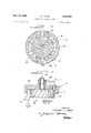
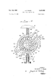
- FIGURE 1 is a central sectional view of a structure embodying the principles of this invention
- FIGURE 2 is a sectional view taken substantially along line 22 of FIGURE 1;
- FIGURE 3 is an end elevational view of the structure shown in FIGURE 1;
- FIGURES 4-9 illustrate various alternative rotor constructions within the principles of this invention.
- FIGURE 10 is a sectional view of an alternative embodiment, illustrating progressive variations in the convolutions defined in both the rotor and housing;
- FIGURE 11 is an elevational view of still another embodiment, having the housing shown in section, and
- FIGURES 12-14 illustrating several embodiments ilustrating various positioning of the fluid entrances and exits, FIGURE 13 particularly illustrating multiple staging of a plurality of entrances and exits and FIGURE 14 paricularly illustrating the fluid exit within the rotor sha t;
- FIGURE 15 illustrates an alternative arrangement whereby the volume of the pumping spaces may be automatically varied
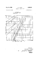
- FIGURE 16 is a graphical illustration of the pump 3 ducing fluid to and from the working spaces.
- the capability of generating extremely high pressure results from ahybrid of technical aspects including the ram effect of a progressively converging work space (the resistance to escaping fluid varies with the cube of the clearance between rotor and housing), the regenerative effect of convolutions E defined in at least one wall of the working space.
- the stator is comprised of a first portion and a second portion 27; portion 20 is cup-shaped having a circular cylindrical outer wall 23 anda hollow interior space 21 opening through flat end wall 22.
- Space 21 is defined by flat interior side wall 21a, perpendicular to the axis of rotation 45 of the rotor, and by a radially outer essentially cylindrical interior wall 211:.
- the exterior side wall 24, opposite from that of the wall 22, is also flat and has a central sleeve 25 projecting therefrom with a cylindrical bore 26 therethrough for journaling a rotor shaft 38.
- the housing portion 27 is comprised of a heavy plate having parallel flat side walls 27a and 27b.
- the plate is generally commensurate in thickness to that of the portion 20 between side walls 22 and 24.
- the portion 27 is mated against the side wall 22 of portion 20 and is coupled thereto by suitable fasteners 29 extending through aligned openings 28 circumferentially spaced above the margins of portions 20 and 27 thereof.
- the power driven rotor B is disposed within the hollow interior-space 21 of the stator and comprises a unitary circular disc 37 and is rotatively carried by shaft 38 extending through the bore 26 of housing portion 20. Suitable seals 39 are disposed within grooving of the portion 20 for sealing against the outer surface of shaft 38.
- the rotor has a convoluted cylindrical outer wall 40 concentric about the axis of rotation and has a pair of flat side walls 41 which are recessed at 41a to reduce the frictional contact between the sides of the rotor and the side walls 27b and 22, the latter walls being in a facesealed relationship (minimal clearance) or varied to permit up to .10 inch clearance depending on allowable flow requirements and economics.
- the rotor and stator cooperate to define the progressively converging working spaces C.
- such taper or convergence is brought about by irregularly shaping the interior Wall 21b of the stator portion 20 while maintaining the outer periphery of the rotor in a generally circular shape.
- the irregular definition of the interior wall 21b is comprised of one or more (here being two) arcuate portions, each extending circumferentially between a mouth 47 and an apex 48 thereof.
- the mouth 47 corresponds to the widest radial spacing between the rotor and the interior wall 21b; the apex 48 corresponds to the closest relationship therebetween.
- each arcuate portion thereby proceeds from a rather wide-spaced relationship with the outer wall 40 of the rotor adjacent to a mouth 47 associated therewith and progressively narrows to a bearing relationship with wall 40 which is substantially tangential to the outer wall 40 adjacent to an apex 48 thereof.
- the rotor B is dimensioned so that said bearing fit will be realized without the rotor actually contacting the stator.
- Other variations for defining the converging spaces C can be envisaged; for example, the wall 21b may be madecircular and spaced from the rotor-.a bafiie mounted on the housing may then be employed to achieve theconvergence between the circular walls.
- the rotor is provided with a plurality of convolutions E on its outer periphery to aid in developing a regenerative reverse flow.
- Each of the convolutions or grooves E extend transversely across the other periphery thereof, and in the preferred embodiment they are generally parallel to the axis 45 of rotation of the rotor.
- the grooves or convolutions are regularly and equicircumferentially spaced about the periphery of the rotor and their presence define arcuate lands 46 out of the remaining peripheral .wall.
- the grooves form in effect a pocket for recirculating fluid in a.
- centrarotational path as it is carried from a mouth 47 to an apex 48 of the working space.
- Such recirculating flow in effect forms a vortex whereby energy is added to the fluidin a number of impulses by the rotors convolutions.
- the pump device is supplied with fluid by means D comprising a pair of fluid inlet passages 35 extending from the outer side 24 of housing portion 20 transverselytherethrough and communicating with a peripheral portion of the space 21 and thereby with the working spaces C.
- the passages 35 are disposed at diametrically opposite positions (see FIGURE 3) of the rotor and each have a threaded nipple 35a for reception of suitable conduit couplings; the inner end of the passages 35 intersect With the periphery of wall 21b.
- a pair of fluid outlet passages 36 are provided, each extending from the outer side 24 of the housing portion 20 transversely therethrough and communicating with a peripheral portion of the interior space 21 and thereby with a working space C.
- the passages 36 are also disposed at diametrically opposite positions (see FIGURE 3) of the rotor and each have a threaded nipple 36a for reception of suitable conduit couplings.
- the inner end of each pas-' sage 36 intersects with the periphery of wall 21b substantially in a tangential manner without extending entirely through the housing portion 20.
- each of the Convolutions E can be varied while keeping within the invention herein.
- FIGURES 4-9 illustrate other variations, all of the varied convolutions being regularly or equicircumferentially spaced about the axis of rotation and each extending entirely transversely across the outer wall of the rotor.
- the particular grooves 49 are semi-circular in cross section and project below the outer surface of the rotor a depth 50 which is generally equal to the radius defining the cross sectional shape of each groove 49; the grooves are spaced apart a distance such that the remaining land 46 therebetween is generally equal in circumferential dimension to the radius of a groove 49.
- substantially cylindrical tunnels or T-grooves 51 are defined in the outer wall of the rotor and project to a depth 52 which is greater than the radius of the circular cross section of each groove '51 but less than the complete diameter thereof; the grooves 51 define substantially larger lands 54 which approximate the diameter of the grooves 51.
- the grooves 55 have straight side walls 55a interconnected by a flat bottom wall 55b; the circumferential width of each groove 55 is generally equal to the lands 56'tl1erebetween and the depth of each groove being generally less than the width thereof.
- the regularly spaced grooves 57 are V- shaped with one wall 57a considerably longer than'the other wall 57b, the depth of the V-shaped groove being generally one half the width of the land 58 defined between the grooves 57.
- the groove 59 initially are defined similar to FIGURE 1, but have a progressive reduction of the volume of each groove such that as they proceed toward the apex of the working space the grooves 59 are reduced to a' nil volume. This can be brought about by progressively moving the center of definition of each groove 59 outwardly beyond the outer wall of the rotor.
- each groove 60 there are essentially two diametrically opposed grooves 60 each having an extremely long leading arcuate surface 60a which terminates against a short radial directed wall 60b which together define the apex of the groove.
- regularly spaced grooves 61 similar to gear tooth construction, are defined; each groove has converging flat sidewalls 62 which terminate in a bottom wall 63.
- the depth of each groove 61 is greater than the depth of grooving shown in FIGURE 5.
- FIG- URE 10 illustrates the additional definition of convolutions 64 on the wall 21b of the housing as well as the rotor.
- These convolutions 64 have a semi-circular configuration; they are initially similar to the convolutions of FIGURE 1 adjacent to the mouth 47 and progressively become less. in volume as they proceed toward the apex 48.
- the convolutions E as defined on the rotor are of the type shown and illustrated in FIGURE 1 and have a slightly greater radius than the grooving 64 on the interior wall of the housing. A double inducement of local regenerative flow is provided by such radially inner and outer grooving.
- the transverse grooving 65 is given a biased path relative to the axis 45 of rotation.
- the bias is in the direction of rotative movement of the fluid and cooperates with the placement of the fluid entrances and outlets (see FIGURE 11) on opposite sides of the rotor so that kinetic energy losses of the fluid, passing through the pump, will be reduced and thereby result in optimizing the efliciency.
- the passages 35 may be defined in the housing portion 20 as described in connection with FIGURE 1 and the fluid outlets 36 may be defined in the housing plate 27.
- the plate 27 may be adjustably rotatable relative to the housing portion 20 thereby providing ability to vary the circumferential dimension of the converging spaces C thereby resulting in a means for optimizing the performance characteristics of the pump for each particular application.
- the relative movement of the entrances and outlets may be used without the com: bination of biased grooving for optimizing pump operation over a wide speed range.
- FIGURES 12 and 13 systems tor operatively connecting the various fluid passages of the pump are illustrated.
- the fluid entrances 35 and fluid exits 36 are independent from each other, although the plurality of entrances may be fed from a common line and similarly the plurality of fluid outlets may be communicated to a common line (see FIGURE 12).
- FIGURE 13 the schematic shows the first fluid entrance 70 connected to a principal source of fluid, the first fluid outlet 71, instead of being communicated with a conduit leading from the pump, is connected to the second fluid entrance 72;
- each of the convolutions comprised in the series E,-have independent radial passage 74 which communicate with an interior periphery 75 of the rotor; stationed within the hollowed interior is a hub 76 having at least two radially diverging channels 77 in communication with a central axially directed fluid exit 78. Fluid is drawn into the pump working spaces by way of typical fluid entrances 35 andleave the working spaces by way of the centripetal action of the fluid tending to work 6 radialy inwardly through passages 74, channel 77 into central outlet 78.
- FIGURE 15 illustrates another embodiment which provides for governing the output pressure in a uniform manner while varying the flow characteristics through the device.
- the embodiment of FIGURE 15 schematically incorporates two housing parts 80 and 81' each arcuately shaped cooperating with sidewalls (not shown) which are generally fixed.
- the arcuate parts each stops 83.
- the fixed pivots 82 are positioned such that they are at diametrically opposite positions relative to the rotor B and permit the arcuate parts to be moved to and from the axis of rotation 45 of the device thereby regulating the clearances adjacent the fluid exits and thereby regulate the apex 48 of each working space.
- Each of the arcuate parts have an inner cylindrical Wall which is defined relative to the fixed pivot so that it will be nonconcentric with respect to the axis of rotation 45.
- a biasing means F which incorporates a pair of coiled compression springs 86 and 88 eflective to normally resiliently urge the ends 80b and 81b of the arouate parts toward a closed or decreasing clearance position.
- the degree to which the springs exert their resilient force may be adjusted by a thumb screw 89 carried in a reaction wall 87.
- the conveyance of fluid to the working spaces may be as shown in FIGURE 1 and conveyance of the fluid away from the working spaces may be as that shown in FIGURE 14 providing for a centripetal action.
- the exit clearances can be changed and thereby the governed pressure may be varied to achieve an optimum outlet pressure for the given conditions of the pump and the type of fluid being carried.
- the adjustment of the clearance between the arcuate housing parts and the rotor gives rise to a divergence ratio H over H (H represents the clearance adjacent the mouth of each working space and H represents the clearance adjacent the apex of each working space).
- This ratio can be influenced by varying H as in the embodiment of FIGURE 14 or H can be varied to provide a variable displacement pump.
- the pump can readily be converted into a variable displacement type by arranging the pivots 82 to be adjacent the fluid exits so that the clearance adjacent the entrance may be more readily adjusted. In this way the slope of the working space at its mouth can be changed and the de-' gree of flow passing through the pump can be varied as opposed to the ultimate outlet pressure.
- FIGURE 16 To illustrate the comparative characteristics of this invention as related to typical single rotor pumps that have been used for achieving the high pressures, reference is made to FIGURE 16.
- Pump pressure is plotted against the input speed of the pump rotor on logarithmic paper to define relatively straight line plots.
- Plot A represents the variation of output pressure for a typical regenerative type centrifugal turbine pump such as that illustrated in the US. Patents 1,665,687 or 2,724,338;
- plot B represents the output pressure variation for a typical pitot tube pump;
- plot C represents the output pressure variation for a typical centrifugal pump.
- the first two of these pumps are characteristically known for their high output pressure from a single rotor.
- the various alternative suggestions show the complete versatility of this type of pump whereby optimum efficiency may be achieved by varying the type of grooving and particularly biasing the grooving relative to the direction of flow; the optimum flow characteristics may be achieved by varying the number of convolutions, the divergence ratio of the working space at the mouth thereof, and by varying the width of the pump taken in a direction parallel to the axis of rotation; the optimum pressure characteristics may be achieved by varying the working space (the divergence ratio) at the apex thereof, varying the volume of the convolutions and the land area as well as the particular shape of the grooving, and multistaging of the fluid entrances and outlets by connecting them in series.
- This pump may also be used in areas such as variable capacity torque transmitting devices comparative to fluid couplings and fluid sheer mechanisms because of its exceptionally high K factor.
- a pump device comprising a stator and a power driven rotor cooperatively related to define at least one fluid working space therebetween, said space being characterized by a progressive convergence between a mouth portion and an apex portion thereof, said progressive convergence being in the general direction of movement of said rotor and proceeding from said mouth portion to said apex portion said rotor having at least one convolution formed therein to define a pocket for inducing regeneration of fluid as said pocket is exposed to the working fluid space during operation of said rotor, and means for continuously introducing fluid to the mouth of said working space and for continuously exhausting pressur- 8 ized fluid from the apex portion of said working space.
- a pump device comprising: a housing defining an interior fluid chamber having an annular wall bounded by a pair of spaced flat side walls; a power driven rotor mounted within said chamber for rotation about a central axis, said rotor having side walls in face-sealed relation with the side walls of said housing chamber, said rotor having an outer annular wall in close contiguous relationship with only a portion of the housing chamber annular wall while other portions of said housing are spaced therefrom, means defining a fluid entrance and a fluid exit for said space, said rotor and housing cooperating to define at least one progressively convergent working space between said fluid entrance and said fluid exit, said rotor having at least one transverse groove defined in the rotor annular wall effective to stimulate a secondary compressible flow of fluid as said rotor turns; and means for continuously introducing fluid to said entrance and means for continuously exhausting pressurized fluid from said exit.
- a pump device as in claim 2, in which said rotor is provided with a plurality of uniformly shaped grooves in the annular wall thereof, said grooves being regularly spaced circumferentially thereabout.
- a pump device as in claim 2, in which said housing has means for automatically adjusting the volume of the working space defined between said housing and rotor to compensate for variations in output pressure thereby governing the output pressure at a predetermined value.
- a pump device as in claim 2, in which said housing and rotor cooperate to define a plurality of progressively convergent working spaces each having an independent entrance and exit.
- a pump device as in claim 3, in which said spaces are irregularly arranged about the circumference of said devices.
- a pump device as in claim 2, in which said housing has a pair of movable parts, each part' thereof being arcuate and having a fixed pivot at one end for rockably adjusting the spacing between said annular walls to vary the volume thereof, and resilient means normally biasing said parts to one position for governing the output pressure thereby.
- each groove has a silhouette, taken along a plane transverse to the axis of rotation, which is generally a sector of a circle.
- a pump device as in claim 3, in which the grooves progressively vary in shape along the circumference of said device.
- a pump device as in claim 4, in which said fluid entrance and exit are on opposite axial sides of said housing, and the transverse centerline of said grooves extend on a bias with respect to the axis of rotation of the device, said bias being generally in the direction of movement of fluid from the entrance to the exit thereby augmenting efficiency.
- a pump device as in claim 2, in which said means for introducing fluid and exhausting fluid comprise trans-v verse passages in said housing effective to respectively communicate with the entrance and exit of said working space.
- a pump device as in claim 2, in which said means for introducing and exhausting fluid comprises radial .pas: sages in said rotor communicating with central passages extending along the axis of rotation of the device.
- a pump device as in claim 1, in which said rotor is provided with a plurality of uniformly shaped grooves in the annular wall thereof, said grooves being regularly spaced circumferentially thereabout.
- a pump device as in claim 1, in which said housing has means for automatically adjusting the volume of the working space defined between said housing and rotor to compensate for variations in output pressure thereby governing the output pressure at a predetermined value.
- each groove has a silhouette, taken along a plane transverse 9 to the axis of rotation, which is generally a sector of a circle.
- a pump device as in claim 13, in which the grooves progressively vary in shape along the circumference of said device.
- a pump device as in claim 1, in which said means for introducing fluid and exhausting fluid comprise transverse passages in said housing effective to respectively communicate with the entrance and exit of said working space.
- a pump device as in claim 1, in which said means for introducing and exhausting fluid comprises radial pas sages in said rotor communicating with central passages extending along the axis of rotation of the device.
Landscapes
- Engineering & Computer Science (AREA)
- Mechanical Engineering (AREA)
- General Engineering & Computer Science (AREA)
- Rotary Pumps (AREA)
Description
' p 24, 1968 A. c. MAMO 3,402,669
CENTRIFUGAL INERTIA PUMP Filed June 1'7, 1966 6 Sheets-Sheet l TION OF E PORTIONS" //vv/vr0 ANTHONY C. M 0
Sept. 24, 1968 A. c. MAMO 3,402,669
CENTRIFUGAL INERTIA PUMP Filed June 17, 1966 I 6 Sheets-Sheet 2 INVENTOR. ANTHONY C. MAMO maj Sept. 24, 1968 A. c. MAMO CENTRIF'UGAL INERTIA PUMP 6 Sheets-Sheet 4 :1 led June 17, 1966 v INVENTOR.
g ANTHONY c. MAMO BY A a 24/ M Sept. 24, 1968 A. c. MAMO 3,402,669
CENTRIFUGAL- INERTIA PUMP Filed June 17, 1966 6 Sheets-Sheet 5 lNl/E/VTOR. ANTHONY 0. M4 M0 BY WQ/ Unitcd States Patent Ofice 3,402,669. 1 CENTRIFUGAL INERTIA PUMP Anthony C. Mamo, Arlington Heights, Ill., assignor to Borg-Warner Corporation, "Chicago, 11]., a corporation oflllinois '-r FiledJune 17, 1966, Ser. No. 558,370
' j 18 Claims. (Cl. 103-97).
I ABSTRACT OF THE DISCLOSURE A rotary pump has a rotor spaced from the housing. Between the rotor and the housing there is a convergent working space in the direction of rotation of the rotor from the inlet to the outlet. The rotor has a series of grooves on its periphery.
This invention relates to rotary high pressure pumps and improvements therein.
In industrial fields requiring the pumping of fluids at relatively high pressures, the pump structures have typically been of the positive displacement or complex multistaging types in order to achieve such high pressures here being considered. These pump types are characterized by relatively high cost of manufacture and relatively limited durability. In the case of the positive displacement type the higher costs result from the extremely close tolerances and careful machining that is necessary for such high pressure utilization; in the case of multistaging the repetitious structure obviously adds the high cost factor. With regard 'to the positive displacement type, the-useful life of such pumps are relatively limited in any application where the fluid might contain varying sizes of grit material which would affect the predetermined tolerances between the elements. In the multistage type the durability and life span would, of course, be limited by the enhanced sealing problems, as well as magnified axial loads, shaft deflection, and end space. Both of these pump types are noted for progressively poorer performance (efllciency) with increasing viscosity of the pumped fluid.
The single-stage centrifugal rotary type pump is free of disadvantages above noted, but is restricted in attainment of high pumping pressures. The stator and rotor elements of a centrifugal pump are not in contacting relationship and thereby contribute to a very low noise level as well as a desirable life span for the pump. However. assuming an ideal centrifugal pump structure and fluid, the mathematical maximum attained pressure is V /ZG for the pump or V /G for the pump and volute wherein V represents the tip velosity of the rotor.
It is accordingly a primary objective of this invention to provide an improved rotary type pump comprised essentially of two parts (a rotor and a stator housing) which is more economical and durableand can pump a variety of fluids ofvarying viscosity, while being able to movethese fluids at relatively high pressures for long periods of continuous'operationwithout being limited by the conventional" centrifugal pump formula V /2G or V /G.
Another object of this invention is to provide a high pressure .type pump which is not dependent upon strict dimensional relationships between the elements, but rather is characterized by a rotor which' -runs free from the stator housing-resulting. in an improved noise level of operation and durability. Another object of this invention is to provide an improved rotary type pump .which is capable of pumping fluids at extremely high pressures and which is characterized by an operational efllciency which progressively improves with an increasing viscosity of the fluid being pumped. i 1
3,402,669 Patented Sept. 24, 1968 housing effective to define a converging pumping space. provided with a fluid entrance and exit, the rotor being movable in the direction of convergence of saidspace and having one or more convolutions for-affecting the' fluid within said space.
Particular structural features pursuant to the above objects and which form a part. of this invention may comprise (a) the use of convolutions or transverse grooving on the rotor or stator housing which are biased in the direction of movement of the fluid and cooperate'with the placement of the fluid entrance and outlet so that the kinetic energy losses of the fluid, passing through the pump, will be reduced and thereby result in optimizing the eificiency; (b) the fluid flow characteristics may be influenced by regulating the transverse dimension of the grooving or convolutions with an increase in width or dimension resulting in more flow, increasing the number of convolutions, or by varying the crescent space at the fluid entranceall of the foregoing resulting in optimizing the flow characteristics; (c) the employment of variations to optimize the output pressure of the pump such as: shaping the grooving or pockets on the rotor or housing so as to provide a relatively large land area between the pockets while still providing suflicient trapping volume for regeneration purposes, providing multistaging without departing from the concept of the single rotor, or varying the crescent space at the fluid exit.
Other objects and advantages of this invention will become more apparent from the following detailed descrip tion taken in connection with the accompanying drawings in which:
FIGURE 1 is a central sectional view of a structure embodying the principles of this invention;
FIGURE 2 is a sectional view taken substantially along line 22 of FIGURE 1;
FIGURE 3 is an end elevational view of the structure shown in FIGURE 1;
FIGURES 4-9 illustrate various alternative rotor constructions within the principles of this invention;
FIGURE 10 is a sectional view of an alternative embodiment, illustrating progressive variations in the convolutions defined in both the rotor and housing;
FIGURE 11 is an elevational view of still another embodiment, having the housing shown in section, and
illustrating biased groove convolutions on the rotor;
FIGURES 12-14 illustrating several embodiments ilustrating various positioning of the fluid entrances and exits, FIGURE 13 particularly illustrating multiple staging of a plurality of entrances and exits and FIGURE 14 paricularly illustrating the fluid exit within the rotor sha t;
FIGURE 15 illustrates an alternative arrangement whereby the volume of the pumping spaces may be automatically varied; and
FIGURE 16 is a graphical illustration of the pump 3 ducing fluid to and from the working spaces. The capability of generating extremely high pressure results from ahybrid of technical aspects including the ram effect of a progressively converging work space (the resistance to escaping fluid varies with the cube of the clearance between rotor and housing), the regenerative effect of convolutions E defined in at least one wall of the working space.
'In more particularity, the stator is comprised of a first portion and a second portion 27; portion 20 is cup-shaped having a circular cylindrical outer wall 23 anda hollow interior space 21 opening through flat end wall 22. Space 21 is defined by flat interior side wall 21a, perpendicular to the axis of rotation 45 of the rotor, and by a radially outer essentially cylindrical interior wall 211:. The exterior side wall 24, opposite from that of the wall 22, is also flat and has a central sleeve 25 projecting therefrom with a cylindrical bore 26 therethrough for journaling a rotor shaft 38.
- The housing portion 27 is comprised of a heavy plate having parallel flat side walls 27a and 27b. The plate is generally commensurate in thickness to that of the portion 20 between side walls 22 and 24. The portion 27 is mated against the side wall 22 of portion 20 and is coupled thereto by suitable fasteners 29 extending through aligned openings 28 circumferentially spaced above the margins of portions 20 and 27 thereof.
The power driven rotor B is disposed within the hollow interior-space 21 of the stator and comprises a unitary circular disc 37 and is rotatively carried by shaft 38 extending through the bore 26 of housing portion 20. Suitable seals 39 are disposed within grooving of the portion 20 for sealing against the outer surface of shaft 38. The rotor has a convoluted cylindrical outer wall 40 concentric about the axis of rotation and has a pair of flat side walls 41 which are recessed at 41a to reduce the frictional contact between the sides of the rotor and the side walls 27b and 22, the latter walls being in a facesealed relationship (minimal clearance) or varied to permit up to .10 inch clearance depending on allowable flow requirements and economics.
To provide for pumping action of fluid, the rotor and stator cooperate to define the progressively converging working spaces C. In the preferred embodiment, such taper or convergence is brought about by irregularly shaping the interior Wall 21b of the stator portion 20 while maintaining the outer periphery of the rotor in a generally circular shape. The irregular definition of the interior wall 21b is comprised of one or more (here being two) arcuate portions, each extending circumferentially between a mouth 47 and an apex 48 thereof. The mouth 47 corresponds to the widest radial spacing between the rotor and the interior wall 21b; the apex 48 corresponds to the closest relationship therebetween. The geometrical centers for the definition of the arcuate portions are offset from the axis 45 of the rotor; each arcuate portion thereby proceeds from a rather wide-spaced relationship with the outer wall 40 of the rotor adjacent to a mouth 47 associated therewith and progressively narrows to a bearing relationship with wall 40 which is substantially tangential to the outer wall 40 adjacent to an apex 48 thereof. The rotor B is dimensioned so that said bearing fit will be realized without the rotor actually contacting the stator. Other variations for defining the converging spaces C can be envisaged; for example, the wall 21b may be madecircular and spaced from the rotor-.a bafiie mounted on the housing may then be employed to achieve theconvergence between the circular walls.
In addition-to the accelerating flow derived from the converging working spaces, the rotor is provided with a plurality of convolutions E on its outer periphery to aid in developing a regenerative reverse flow. Each of the convolutions or grooves E extend transversely across the other periphery thereof, and in the preferred embodiment they are generally parallel to the axis 45 of rotation of the rotor. The grooves or convolutions are regularly and equicircumferentially spaced about the periphery of the rotor and their presence define arcuate lands 46 out of the remaining peripheral .wall. The grooves form in effect a pocket for recirculating fluid in a. centrarotational path as it is carried from a mouth 47 to an apex 48 of the working space. Such recirculating flow in effect forms a vortex whereby energy is added to the fluidin a number of impulses by the rotors convolutions.
In the preferred embodiment, the pump device is supplied with fluid by means D comprising a pair of fluid inlet passages 35 extending from the outer side 24 of housing portion 20 transverselytherethrough and communicating with a peripheral portion of the space 21 and thereby with the working spaces C. The passages 35 are disposed at diametrically opposite positions (see FIGURE 3) of the rotor and each have a threaded nipple 35a for reception of suitable conduit couplings; the inner end of the passages 35 intersect With the periphery of wall 21b.
Similarly, a pair of fluid outlet passages 36 are provided, each extending from the outer side 24 of the housing portion 20 transversely therethrough and communicating with a peripheral portion of the interior space 21 and thereby with a working space C. The passages 36 are also disposed at diametrically opposite positions (see FIGURE 3) of the rotor and each have a threaded nipple 36a for reception of suitable conduit couplings. The inner end of each pas-' sage 36 intersects with the periphery of wall 21b substantially in a tangential manner without extending entirely through the housing portion 20. It should be noted that the arcuate working spaces C interposed between each mouth and apex are on directly opposite sides of the device and thereby afford a balanced hydraulic condition of the centrifugal fluid forces. (In FIGURE 31, the hydraulic forces are balanced by nonsymmetric porting.)
The cross sectional configuration of each of the Convolutions E can be varied while keeping within the invention herein. In addition to the convolutions of the preferred embodiment, FIGURES 4-9 illustrate other variations, all of the varied convolutions being regularly or equicircumferentially spaced about the axis of rotation and each extending entirely transversely across the outer wall of the rotor. In FIGURE 1, the particular grooves 49 are semi-circular in cross section and project below the outer surface of the rotor a depth 50 which is generally equal to the radius defining the cross sectional shape of each groove 49; the grooves are spaced apart a distance such that the remaining land 46 therebetween is generally equal in circumferential dimension to the radius of a groove 49. In FIGURE 4, substantially cylindrical tunnels or T-grooves 51 are defined in the outer wall of the rotor and project to a depth 52 which is greater than the radius of the circular cross section of each groove '51 but less than the complete diameter thereof; the grooves 51 define substantially larger lands 54 which approximate the diameter of the grooves 51. In FIGURE 5, the grooves 55 have straight side walls 55a interconnected by a flat bottom wall 55b; the circumferential width of each groove 55 is generally equal to the lands 56'tl1erebetween and the depth of each groove being generally less than the width thereof. In FIGURE 6, the regularly spaced grooves 57 are V- shaped with one wall 57a considerably longer than'the other wall 57b, the depth of the V-shaped groove being generally one half the width of the land 58 defined between the grooves 57. In FIGURE 7, the groove 59 initially are defined similar to FIGURE 1, but have a progressive reduction of the volume of each groove such that as they proceed toward the apex of the working space the grooves 59 are reduced to a' nil volume. This can be brought about by progressively moving the center of definition of each groove 59 outwardly beyond the outer wall of the rotor. In FIGURE 8, there are essentially two diametrically opposed grooves 60 each having an extremely long leading arcuate surface 60a which terminates against a short radial directed wall 60b which together define the apex of the groove. In FIGURE 9, regularly spaced grooves 61, similar to gear tooth construction, are defined; each groove has converging flat sidewalls 62 which terminate in a bottom wall 63. The depth of each groove 61 is greater than the depth of grooving shown in FIGURE 5.
Further variations can be incorporated into the design of the device such as shown in FIGURES and 11; FIG- URE 10 illustrates the additional definition of convolutions 64 on the wall 21b of the housing as well as the rotor. These convolutions 64 have a semi-circular configuration; they are initially similar to the convolutions of FIGURE 1 adjacent to the mouth 47 and progressively become less. in volume as they proceed toward the apex 48. The convolutions E as defined on the rotor are of the type shown and illustrated in FIGURE 1 and have a slightly greater radius than the grooving 64 on the interior wall of the housing. A double inducement of local regenerative flow is provided by such radially inner and outer grooving.
In FIGURE 11, the transverse grooving 65 is given a biased path relative to the axis 45 of rotation. The bias is in the direction of rotative movement of the fluid and cooperates with the placement of the fluid entrances and outlets (see FIGURE 11) on opposite sides of the rotor so that kinetic energy losses of the fluid, passing through the pump, will be reduced and thereby result in optimizing the efliciency. To facilitate the placement of the fluid entrances and outlets, the passages 35 may be defined in the housing portion 20 as described in connection with FIGURE 1 and the fluid outlets 36 may be defined in the housing plate 27. Further, the plate 27 may be adjustably rotatable relative to the housing portion 20 thereby providing ability to vary the circumferential dimension of the converging spaces C thereby resulting in a means for optimizing the performance characteristics of the pump for each particular application. The relative movement of the entrances and outlets may be used without the com: bination of biased grooving for optimizing pump operation over a wide speed range.
Turning now to FIGURES 12 and 13, systems tor operatively connecting the various fluid passages of the pump are illustrated. -In the preferred embodiment of FIGURE 1, the fluid entrances 35 and fluid exits 36 are independent from each other, although the plurality of entrances may be fed from a common line and similarly the plurality of fluid outlets may be communicated to a common line (see FIGURE 12). However, other arrangements may be envisioned for this type of pump wherein multistaging can be incorporated. In FIGURE 13, the schematic shows the first fluid entrance 70 connected to a principal source of fluid, the first fluid outlet 71, instead of being communicated with a conduit leading from the pump, is connected to the second fluid entrance 72;
thereby immediately reworking the output of the first working space and sending it to a second stage of the pump by way of fluid entrance 72. The total fluid output is taken from fluid outlet 73 and applied to a specific loadfThus, it is a distinct novel characteristic of this pump'that permits it to be easily connected for multistaging with the same rotor in the same housing (in counterdistinction to prior art where additional rotors must be utilized) and without changing the flow radii. With this type of multistaging, the Working spaces may be irregularly spaced about the axis 45 to balance a constantly increasing pressure through the several spaces C.
,In FIGURE 14, each of the convolutions, comprised in the series E,-have independent radial passage 74 which communicate with an interior periphery 75 of the rotor; stationed within the hollowed interior is a hub 76 having at least two radially diverging channels 77 in communication with a central axially directed fluid exit 78. Fluid is drawn into the pump working spaces by way of typical fluid entrances 35 andleave the working spaces by way of the centripetal action of the fluid tending to work 6 radialy inwardly through passages 74, channel 77 into central outlet 78.
FIGURE 15 illustrates another embodiment which provides for governing the output pressure in a uniform manner while varying the flow characteristics through the device. To this end, the embodiment of FIGURE 15 schematically incorporates two housing parts 80 and 81' each arcuately shaped cooperating with sidewalls (not shown) which are generally fixed. The arcuate parts each stops 83. The fixed pivots 82 are positioned such that they are at diametrically opposite positions relative to the rotor B and permit the arcuate parts to be moved to and from the axis of rotation 45 of the device thereby regulating the clearances adjacent the fluid exits and thereby regulate the apex 48 of each working space. Each of the arcuate parts have an inner cylindrical Wall which is defined relative to the fixed pivot so that it will be nonconcentric with respect to the axis of rotation 45.
To achieve a regulated or governed outlet pressure a biasing means F is employed which incorporates a pair of coiled compression springs 86 and 88 eflective to normally resiliently urge the ends 80b and 81b of the arouate parts toward a closed or decreasing clearance position. The degree to which the springs exert their resilient force may be adjusted by a thumb screw 89 carried in a reaction wall 87. The conveyance of fluid to the working spaces may be as shown in FIGURE 1 and conveyance of the fluid away from the working spaces may be as that shown in FIGURE 14 providing for a centripetal action. By adjustment of the thumb screw, the exit clearances can be changed and thereby the governed pressure may be varied to achieve an optimum outlet pressure for the given conditions of the pump and the type of fluid being carried. The adjustment of the clearance between the arcuate housing parts and the rotor gives rise to a divergence ratio H over H (H represents the clearance adjacent the mouth of each working space and H represents the clearance adjacent the apex of each working space). This ratio can be influenced by varying H as in the embodiment of FIGURE 14 or H can be varied to provide a variable displacement pump. The pump can readily be converted into a variable displacement type by arranging the pivots 82 to be adjacent the fluid exits so that the clearance adjacent the entrance may be more readily adjusted. In this way the slope of the working space at its mouth can be changed and the de-' gree of flow passing through the pump can be varied as opposed to the ultimate outlet pressure.
To illustrate the comparative characteristics of this invention as related to typical single rotor pumps that have been used for achieving the high pressures, reference is made to FIGURE 16. In this chart, pumps of the same working diameter have been utilized (here being 3 inches). Pump pressure is plotted against the input speed of the pump rotor on logarithmic paper to define relatively straight line plots. Plot A represents the variation of output pressure for a typical regenerative type centrifugal turbine pump such as that illustrated in the US. Patents 1,665,687 or 2,724,338; plot B represents the output pressure variation for a typical pitot tube pump; plot C represents the output pressure variation for a typical centrifugal pump. The first two of these pumps are characteristically known for their high output pressure from a single rotor. Each of these typical prior art pumps were rated with water as the pumped fluid except that a subplot D was provided for the regenerative type pump to show the performance drop when a viscous fluid is substituted for water, the viscous fluid having a rating of 3,000 SUS. Plot D shows how increase of viscosity of the pumped fluid reduces output performance.
Various embodiments of the pump of this invention were tested and all showed plot variations considerably higher in output pressure for any given input speed than that shown for the prior art centrifugal, or one moving part structures. For example, a rotor with 40 convolutions along its outer periphery with lands 46 dimensioned with a width of .125 of an inch gave the plot E (pump construction similar to FIGURE 1). Similarly a rotor with 18 equicircumferentially spaced convol utions and a land dimension of .375 of an inch was also tested to give plot F (construction also similar to FIGURE 1). Both plots E and F were derived from a pump using a fluid with a viscosity of 3,000 SUS at 100 F. Plots G and H were respectively for rotors having the same characteristics as plots E and F but tested with a fluid medium having a viscosity of 200 SUS at 100 F.
It is clear from this comparative chart that the output pressures from the construction of this invention were outstandingly greater than that for the closest known prior art constructions and that pump efficiency rises with an increase of viscosity of the pump fluid contrary to the prior art. The pump output flows are consistently steady, the noise level comparatively low, and cavitation was not observed or induced in any combination of flows and pressures for the range of embodiments illustrated. The nonexistence of sliding parts or rubbing parts in the pump permits this device to be used at very high rotative speeds, even encompasing gas turbine speeds. The operating speeds would not necessarily be limited by the strength of materials used for the rotor as the generated pressures subtract from the stress of the rotating parts.
The various alternative suggestions show the complete versatility of this type of pump whereby optimum efficiency may be achieved by varying the type of grooving and particularly biasing the grooving relative to the direction of flow; the optimum flow characteristics may be achieved by varying the number of convolutions, the divergence ratio of the working space at the mouth thereof, and by varying the width of the pump taken in a direction parallel to the axis of rotation; the optimum pressure characteristics may be achieved by varying the working space (the divergence ratio) at the apex thereof, varying the volume of the convolutions and the land area as well as the particular shape of the grooving, and multistaging of the fluid entrances and outlets by connecting them in series.
The extreme economy of this two part pump and its exhibited characteristics would be relatively useful in such applications as oil furnace pumps where its greater economy, longer life and lower noise level, would be suitable. Other areas of application might include means for pumping plastic, molten metal, blood, liquid rubber, paints and viscous cosmetics. This pump may also be used in areas such as variable capacity torque transmitting devices comparative to fluid couplings and fluid sheer mechanisms because of its exceptionally high K factor.
While I have described my invention in connection with one specific embodiment and other alternative suggestions, it is to be understood that this is by way of illustration and not by way of limitation and the scope of my invention is defined solely by the appended claims which should be construed as broadly as the prior art will permit.
I claim:
1. A pump device comprising a stator and a power driven rotor cooperatively related to define at least one fluid working space therebetween, said space being characterized by a progressive convergence between a mouth portion and an apex portion thereof, said progressive convergence being in the general direction of movement of said rotor and proceeding from said mouth portion to said apex portion said rotor having at least one convolution formed therein to define a pocket for inducing regeneration of fluid as said pocket is exposed to the working fluid space during operation of said rotor, and means for continuously introducing fluid to the mouth of said working space and for continuously exhausting pressur- 8 ized fluid from the apex portion of said working space. 2. A pump device comprising: a housing defining an interior fluid chamber having an annular wall bounded by a pair of spaced flat side walls; a power driven rotor mounted within said chamber for rotation about a central axis, said rotor having side walls in face-sealed relation with the side walls of said housing chamber, said rotor having an outer annular wall in close contiguous relationship with only a portion of the housing chamber annular wall while other portions of said housing are spaced therefrom, means defining a fluid entrance and a fluid exit for said space, said rotor and housing cooperating to define at least one progressively convergent working space between said fluid entrance and said fluid exit, said rotor having at least one transverse groove defined in the rotor annular wall effective to stimulate a secondary compressible flow of fluid as said rotor turns; and means for continuously introducing fluid to said entrance and means for continuously exhausting pressurized fluid from said exit.
3. A pump device, as in claim 2, in which said rotor is provided with a plurality of uniformly shaped grooves in the annular wall thereof, said grooves being regularly spaced circumferentially thereabout.
4. A pump device, as in claim 2, in which said housing has means for automatically adjusting the volume of the working space defined between said housing and rotor to compensate for variations in output pressure thereby governing the output pressure at a predetermined value.
5. A pump device, as in claim 2, in which said housing and rotor cooperate to define a plurality of progressively convergent working spaces each having an independent entrance and exit.
6. A pump device, as in claim 3, in which said spaces are irregularly arranged about the circumference of said devices.
7. A pump device, as in claim 2, in which said housing has a pair of movable parts, each part' thereof being arcuate and having a fixed pivot at one end for rockably adjusting the spacing between said annular walls to vary the volume thereof, and resilient means normally biasing said parts to one position for governing the output pressure thereby.
8. A pump device, as in claim 3, in which each groove has a silhouette, taken along a plane transverse to the axis of rotation, which is generally a sector of a circle.
9. A pump device, as in claim 3, in which the grooves progressively vary in shape along the circumference of said device.
10. A pump device, as in claim 4, in which said fluid entrance and exit are on opposite axial sides of said housing, and the transverse centerline of said grooves extend on a bias with respect to the axis of rotation of the device, said bias being generally in the direction of movement of fluid from the entrance to the exit thereby augmenting efficiency.
11. A pump device, as in claim 2, in which said means for introducing fluid and exhausting fluid comprise trans-v verse passages in said housing effective to respectively communicate with the entrance and exit of said working space.
12. A pump device, as in claim 2, in which said means for introducing and exhausting fluid comprises radial .pas: sages in said rotor communicating with central passages extending along the axis of rotation of the device.
13. A pump device, as in claim 1, in which said rotor is provided with a plurality of uniformly shaped grooves in the annular wall thereof, said grooves being regularly spaced circumferentially thereabout.
14. A pump device, as in claim 1, in which said housing has means for automatically adjusting the volume of the working space defined between said housing and rotor to compensate for variations in output pressure thereby governing the output pressure at a predetermined value.
15. A pump device, as in claim 13, in which each groove has a silhouette, taken along a plane transverse 9 to the axis of rotation, which is generally a sector of a circle.
16. A pump device, as in claim 13, in which the grooves progressively vary in shape along the circumference of said device.
17. A pump device, as in claim 1, in which said means for introducing fluid and exhausting fluid comprise transverse passages in said housing effective to respectively communicate with the entrance and exit of said working space.
18. A pump device, as in claim 1, in which said means for introducing and exhausting fluid comprises radial pas sages in said rotor communicating with central passages extending along the axis of rotation of the device.
References Cited UNITED STATES PATENTS 1,783,209 12/1930 Wilsey 103126 2,228,124 1/ 1941 Northey 103-96 3,03 7,457 6/ 1962 Sternlicht 10384 FOREIGN PATENTS 590,733 3/ 1925 France. 720,485 5/ 1942 Germany. 875,439 8/ 1961 Great Britain.
ROBERT M. WALKER, Primary Examiner.
Priority Applications (1)
| Application Number | Priority Date | Filing Date | Title |
|---|---|---|---|
| US558370A US3402669A (en) | 1966-06-17 | 1966-06-17 | Centrifugal inertia pump |
Applications Claiming Priority (1)
| Application Number | Priority Date | Filing Date | Title |
|---|---|---|---|
| US558370A US3402669A (en) | 1966-06-17 | 1966-06-17 | Centrifugal inertia pump |
Publications (1)
| Publication Number | Publication Date |
|---|---|
| US3402669A true US3402669A (en) | 1968-09-24 |
Family
ID=24229284
Family Applications (1)
| Application Number | Title | Priority Date | Filing Date |
|---|---|---|---|
| US558370A Expired - Lifetime US3402669A (en) | 1966-06-17 | 1966-06-17 | Centrifugal inertia pump |
Country Status (1)
| Country | Link |
|---|---|
| US (1) | US3402669A (en) |
Cited By (7)
| Publication number | Priority date | Publication date | Assignee | Title |
|---|---|---|---|---|
| US5011631A (en) * | 1989-11-14 | 1991-04-30 | Sean Hwang | Turbo-jet aerator |
| US5215429A (en) * | 1992-01-10 | 1993-06-01 | General Signal Corporation | Regenerative turbine having predetermined clearance relationship between channel ring and impeller |
| US5281083A (en) * | 1991-06-18 | 1994-01-25 | Hitachi, Ltd. | Vortex flow blower |
| US5456575A (en) * | 1994-05-16 | 1995-10-10 | Varian Associates, Inc. | Non-centric improved pumping stage for turbomolecular pumps |
| FR2755479A1 (en) * | 1996-08-28 | 1998-05-07 | Bosch Gmbh Robert | CIRCULATION PUMP, ESPECIALLY FOR TRANSFERRING FUEL FROM A TANK TO A THERMAL ENGINE |
| US20080056885A1 (en) * | 2006-08-31 | 2008-03-06 | Varian, S.P.A | Vacuum pumps with improved pumping channel configurations |
| US20120134796A1 (en) * | 2010-11-26 | 2012-05-31 | Zheng Zhao | Volute and drainage pump |
Citations (6)
| Publication number | Priority date | Publication date | Assignee | Title |
|---|---|---|---|---|
| FR590733A (en) * | 1924-02-14 | 1925-06-22 | Wave train emission system, in various fluid media | |
| US1783209A (en) * | 1926-12-29 | 1930-12-02 | James B Tuthill | Spur gear pump |
| US2228124A (en) * | 1937-05-03 | 1941-01-07 | Northey Arthur John | Rotary pump |
| DE720485C (en) * | 1936-10-07 | 1942-05-07 | Gustav Stromeier | Conveyor device for liquids |
| GB875439A (en) * | 1959-04-13 | 1961-08-23 | Northey Rotary Compressors Ltd | Improvements in circumferential flow pumps |
| US3037457A (en) * | 1959-08-26 | 1962-06-05 | Gen Electric | Pumps |
-
1966
- 1966-06-17 US US558370A patent/US3402669A/en not_active Expired - Lifetime
Patent Citations (6)
| Publication number | Priority date | Publication date | Assignee | Title |
|---|---|---|---|---|
| FR590733A (en) * | 1924-02-14 | 1925-06-22 | Wave train emission system, in various fluid media | |
| US1783209A (en) * | 1926-12-29 | 1930-12-02 | James B Tuthill | Spur gear pump |
| DE720485C (en) * | 1936-10-07 | 1942-05-07 | Gustav Stromeier | Conveyor device for liquids |
| US2228124A (en) * | 1937-05-03 | 1941-01-07 | Northey Arthur John | Rotary pump |
| GB875439A (en) * | 1959-04-13 | 1961-08-23 | Northey Rotary Compressors Ltd | Improvements in circumferential flow pumps |
| US3037457A (en) * | 1959-08-26 | 1962-06-05 | Gen Electric | Pumps |
Cited By (9)
| Publication number | Priority date | Publication date | Assignee | Title |
|---|---|---|---|---|
| US5011631A (en) * | 1989-11-14 | 1991-04-30 | Sean Hwang | Turbo-jet aerator |
| US5281083A (en) * | 1991-06-18 | 1994-01-25 | Hitachi, Ltd. | Vortex flow blower |
| US5215429A (en) * | 1992-01-10 | 1993-06-01 | General Signal Corporation | Regenerative turbine having predetermined clearance relationship between channel ring and impeller |
| US5456575A (en) * | 1994-05-16 | 1995-10-10 | Varian Associates, Inc. | Non-centric improved pumping stage for turbomolecular pumps |
| FR2755479A1 (en) * | 1996-08-28 | 1998-05-07 | Bosch Gmbh Robert | CIRCULATION PUMP, ESPECIALLY FOR TRANSFERRING FUEL FROM A TANK TO A THERMAL ENGINE |
| US20080056885A1 (en) * | 2006-08-31 | 2008-03-06 | Varian, S.P.A | Vacuum pumps with improved pumping channel configurations |
| US7628577B2 (en) * | 2006-08-31 | 2009-12-08 | Varian, S.P.A. | Vacuum pumps with improved pumping channel configurations |
| US20120134796A1 (en) * | 2010-11-26 | 2012-05-31 | Zheng Zhao | Volute and drainage pump |
| US9777745B2 (en) * | 2010-11-26 | 2017-10-03 | Johnson Electric S.A. | Pump housing and drainage pump |
Similar Documents
| Publication | Publication Date | Title |
|---|---|---|
| US4408952A (en) | Lateral channel pump | |
| EP1451472B1 (en) | Improved thrust bearing for multistage centrifugal pumps | |
| US2927536A (en) | Variable capacity pump | |
| US3771900A (en) | Graduated screw pump | |
| US4551080A (en) | Variable displacement sliding vane pump/hydraulic motor | |
| US2631544A (en) | Rotary vane pump | |
| US2101051A (en) | Rotary fluid displacement device | |
| US2393223A (en) | Hydraulic motor | |
| US3016019A (en) | Fluid power converter | |
| US3402669A (en) | Centrifugal inertia pump | |
| US4236867A (en) | Friction reducing arrangement for hydraulic machines | |
| JPH03145595A (en) | Controllable vortex regeneration pump | |
| GB1085419A (en) | Centrifugal pumps | |
| US2880677A (en) | Variable volume vane pump | |
| US2992616A (en) | Fluid power converter | |
| US3711227A (en) | Vane-type fluid pump | |
| US2969743A (en) | Rotary slidable-vane machines | |
| US3495539A (en) | Rotary pump | |
| US3907456A (en) | Centrifugal pump | |
| US3190074A (en) | Hydraulic transmission | |
| US4021165A (en) | Rotative machine for fluids with spiral-like passages and vane wheels | |
| US2255786A (en) | Reversible vane type fluid motor | |
| US1199359A (en) | Hydraulic device for transmitting power. | |
| US2636442A (en) | Centrifugal pump | |
| US2391360A (en) | Hydraulic fluid motor |