US3402661A - Control means for traveling platen roller in bed and cylinder printing machines - Google Patents
Control means for traveling platen roller in bed and cylinder printing machines Download PDFInfo
- Publication number
- US3402661A US3402661A US494815A US49481565A US3402661A US 3402661 A US3402661 A US 3402661A US 494815 A US494815 A US 494815A US 49481565 A US49481565 A US 49481565A US 3402661 A US3402661 A US 3402661A
- Authority
- US
- United States
- Prior art keywords
- printing
- tray
- platen
- bed
- spring
- Prior art date
- Legal status (The legal status is an assumption and is not a legal conclusion. Google has not performed a legal analysis and makes no representation as to the accuracy of the status listed.)
- Expired - Lifetime
Links
- 230000007246 mechanism Effects 0.000 description 10
- 230000000994 depressogenic effect Effects 0.000 description 9
- 239000004677 Nylon Substances 0.000 description 8
- 229920001778 nylon Polymers 0.000 description 8
- 230000009471 action Effects 0.000 description 7
- 230000003213 activating effect Effects 0.000 description 5
- 239000011435 rock Substances 0.000 description 5
- 230000006835 compression Effects 0.000 description 4
- 238000007906 compression Methods 0.000 description 4
- 230000003028 elevating effect Effects 0.000 description 4
- 230000001965 increasing effect Effects 0.000 description 4
- OKTJSMMVPCPJKN-UHFFFAOYSA-N Carbon Chemical compound [C] OKTJSMMVPCPJKN-UHFFFAOYSA-N 0.000 description 2
- 229910052799 carbon Inorganic materials 0.000 description 2
- 230000000881 depressing effect Effects 0.000 description 2
- NJPPVKZQTLUDBO-UHFFFAOYSA-N novaluron Chemical compound C1=C(Cl)C(OC(F)(F)C(OC(F)(F)F)F)=CC=C1NC(=O)NC(=O)C1=C(F)C=CC=C1F NJPPVKZQTLUDBO-UHFFFAOYSA-N 0.000 description 2
- 230000001105 regulatory effect Effects 0.000 description 2
- 125000006850 spacer group Chemical group 0.000 description 2
- LFQSCWFLJHTTHZ-UHFFFAOYSA-N Ethanol Chemical compound CCO LFQSCWFLJHTTHZ-UHFFFAOYSA-N 0.000 description 1
- 230000004075 alteration Effects 0.000 description 1
- 238000013459 approach Methods 0.000 description 1
- 230000001276 controlling effect Effects 0.000 description 1
- 238000010586 diagram Methods 0.000 description 1
- 230000000694 effects Effects 0.000 description 1
- 230000004048 modification Effects 0.000 description 1
- 238000012986 modification Methods 0.000 description 1
- 230000009467 reduction Effects 0.000 description 1
- 239000007787 solid Substances 0.000 description 1
Images


Classifications
-
- B—PERFORMING OPERATIONS; TRANSPORTING
- B41—PRINTING; LINING MACHINES; TYPEWRITERS; STAMPS
- B41F—PRINTING MACHINES OR PRESSES
- B41F3/00—Cylinder presses, i.e. presses essentially comprising at least one cylinder co-operating with at least one flat type-bed
- B41F3/46—Details
- B41F3/58—Driving, synchronising, or control gear
- B41F3/80—Driving, synchronising, or control gear for impression cylinders
Definitions
- a printing machine for use with portable printing means such as credit cards, the machine including a fixed base, a carriage mounted on the base, and a tray adapted for reciprocating travel on the base with respect to the carriage.
- the tray includes a print bed portion for receiving the credit card and any other suitable print elements.
- a platen assembly which may be impelled into one of a plurality of predetermined printing positions with respect to the print bed.
- the platen assembly including a platen rotatably mounted thereon, is impelled into one of the predetermined printing positions when the tray is moved in a first direction during the imprinting stroke. It is then retracted to a non-printing positon when the tray is moved in the opposite direction during a return stroke.
- the present invention relates to a printing machine and, more particularly, to an improved printing machine for recording data on documents from individual printing devices, of a kind suitable for use as identification tokens, by impressing a platen across the face of the document inserted between the path of the platen and the printing device.
- Such printing machines are generally utilized in retail sales systems wherein sales are made on credit to enable data in possession of the individual to be printed upon a suitable sales record from which the individual may be later billed.
- the sales record comprises a single sheet or a form set having several copy sheets the thickness of the form set varying in accordance with the number of copy sheets which number of copy sheets may vary upon the particular transaction being made.
- the sales record might be fairly uniform and a few different types of known printing devices employed could vary in thickness.
- printing systems of the type disclosed above it is well known that in order to obtain uniform and optimum printing pressure on documents and printing devices having varied thicknesses, it is necessary to compensate for the difference in thickness encountered in performing each separate imprint operation.
- the general purpose of this invention is to provide a novel printing machine which overcomes the above noted difilculties by automatically compensating for varying thicknesses among printing plates and/or sales documents.
- a printing machine which contemplates a simple yet efiicient means for automatically lowering the printing platen, prior to an imprint, into a chosen one of two or more imprinting positions, each position being spaced at a different distance from the print bed and having been pre-set in accordance with the thicknesses of the particular printing plates or sales forms to be used to obtain uniform and optimum printing pressure for producing a high quality imprint during each printing operation.
- a platen mechanism having a resiliency which is common to each of the above printing positions allowing for additonal slight variations in printing plates, sales documents and/or the type height raised above the printing plate surface.
- the particular embodiment of the invention shown is electrically operated and automatically initiates the printing cycle operation simultaneously with the selection of any one of the roller platen printing positions.
- Objects of the invention are toprovide a printing machine which produces clear cut and uniform printing, which operates conveniently and with little effort, which permits the roller platen during a printing operation to be automatically spaced at a chosen one of two or more pro-selected printing positions, and simultaneously upon selection of any one of the printing positions initiate the printing cycle for accomplishing a high quality imprint, and in addition which provides for collateral compensation to account for the slight additional thickness variations encountered by the roller platen during an imprint.
- FIGURE 1 is a front perspective view of an electrical imprinter constructed in accordance with the principles of the present invention.
- FIGURE 2 is a plan view of the novel imprinter shown in FIGURE 1.
- FIGURE 3 shows a side elevation of the imprinting machine taken on the line 33 of FIGURE 2.
- FIGURE 4 is a cross sectional view of the machine taken along line 44 of FIGURE 3.
- FIGURES 5 and 6 are sectional views of the platen roller assembly taken on the line 55 of FIGURE 4. at different points in time of travel by the tray 25 once an imprint cycle has been initiated.
- FIGURE 7 is a sectional view of the platen roller assembly taken during a printing operation and disclosing a further improved version of the present invention.
- FIGURE 8 is a sectional view of the machine disclosing a mechanism for positioning and braking the tray, taken on the line 8-8 of FIGURE 3.
- FIGURE 9 is an electrical schematic diagram employed with the machine.
- FIGURE 1 One form of the present invention is illustrated in FIGURE 1 as embodied in a motor-operated printing machine adapted to transfer impressions from printing plates 21 and 22, having raised-type characters, onto document copy or copies comprising a form set 23 which when placed in printing position overlies the printing plates.
- the form set 23 may be in the form of an eightycolumn or fifty-one column size with interlaced carbon sheets for producing multiple copies.
- a platen roller 24 is used for transferring information to the form set by means ofconstant printing pressure engagement with the raised type on the printing plate same when a movable tray 29, on which the printing plates and form set are placed, is impelled to travel under the platen roller.
- the platen roller described in the present invention is of the dry type being particularly adapted for use with carbon-type impression forms, a modified roller of the ink impregnated type, as disclosed in US. Patent No. 2,629,730 to Gilbert, may be employed.
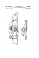
- FIGURES l, 2 and 3 The printing machine shown in FIGURES l, 2 and 3 comprises main frame 25 including pair of side walls 26 and 27 integrally connected at their mid-sections by a connecting bar 28 which extends between the entire length of the side walls.
- the upper portion of the frame 25 forms a U-shaped track which is adapted for enabling a tray 29 to slideably travel thereon in a controlled reciprocating motion as will hereinafter be described in detail.
- the four corners of the bottom area of tray 29 are provided with bearings 30 to minimize friction or enhance sliding action when the tray is travelling with respect to the main frame 25.
- the exterior of the traveling tray bears a pair of anvils 31 and 32, which surfaces define a print bed plane, for supporting thereon printing plates 21 and 22 respectively.
- anvils 31 and 32 Between each anvil 31, 32 and the exterior of the tray are sheet guide members 33 and 34 each to each, enabling the printing plates to be properly positioned and secured upon the anvil surfaces.
- Adjacent anvil 32 is a further anvil 35 upon which may be located, by way of receiving pins 36, a printing plate indicating a dealer or user identification.
- Shoulders 39 and 41 on the sides of tray 25 have several functions one of which is to allow for proper positioning of form sets 23 on the print bed plane. If desired shoulder 39 may be made adjustable so that the tray might accommodate form-sets having varying widths.
- a stop pin 42 neighboring platen 24, is used for positioning the attached front end of the form set on the tray.
- a clamp 44 of obtuse configuration having a pair of side ear portions 45 formed at right angles thereto about the center of each of the clamp sides.
- the side ear portions are intersected by and pivotable about one of a pair of pins 46, each pin being loosely secured within a cavity in the respective opposite sides of the tray 29 beneath the level of the print bed plane.
- the rear portion of the clamp 44 as shown in FIGURE 3, is urged upwardly by tension springs 47 seated within tray cut-outs 48 thus biasing the clamp in a clockwise direction about pivot pins 46 to press the forward end of the clamp against the friction coated surface of raised pedestal 43 for fastening a form set thereto.
- Push-button actuator and platen adjustment When the operator depresses a selected one of the four buttons denoted as A, B, C, and D in FIGURE 1, he simultaneously energizes the drive mechanism and accurately establishes the proper clearance between the print bed plane anvils 31, 32 and platen roller 24 for a related form set thickness yet in each instance for an identical printing plate thickness, thus automatically allowing form sets of different thicknesses to be readily and clearly printed upon by merely selecting and depressing a selected button for a corresponding set form set thickness which may be easily predetermined.
- the form sets employed differ only by the number of additional copy sheets and/ or carbon in the set therefore a system might be adapted so that the button depressed for the basic form set would be A, button B would be depressed when a form set incorporates an additional copy sheet, and so on.
- the apparatus for accomplishing the above function is mainly located within the inverted U-shaped unit 51 mounted by appropriate means to side walls 26 and 27 of main frame 25 to extend over an area traversed by the traveling tray.
- unit 51 Within unit 51 is the two part platen roller 24 separated by spacer 52 and rotatably set on shaft 53, which shaft is received through the lower portions of arms 54, 55 of a bracket assembly 56, to lie about an axis parallel to the print bed plane.
- the entire bracket assembly 56 is supported for pivotable motion about a rod 57 secured to and extending across the unit 51. By use of suitable spacers on rod 57 the bracket assembly may be properly positioned for roller alignment with the anvil surfaces.
- Bracket assembly 56 further comprises a member 61 which in the preferred embodiment is a torsion spring fixed to arm 54 and protracted across the width of the bracket assembly to freely protrude through arm 55.
- a member 61 which in the preferred embodiment is a torsion spring fixed to arm 54 and protracted across the width of the bracket assembly to freely protrude through arm 55.
- the torsion spring is bent at approximately a ninety degree angle to form a leg encased in a nylon shoe 62 the lower edge of which extends downwardly towards the tray surface 29 and below the upper surface of shoulder 41, the shoe being situated in a path traveled by the shoulder 41, which shoulder is co-extensive with the printing bed area, so as to engage the same in a cammed type action when the tray is driven under bracket assembly 56 during a printing operation for purposes which will hereinafter be explained.
- bracket assembly 56 may be described as the control end in that it contains four individually adjustable screws 64, 65, 66, and 67, each being provided with upwardly protruding latch ends for individually yet accurately controlling a pre-determined clearance between the print bed plane and the platen during an imprinting operation.
- Bracket assembly 56 in its normal inactivated state, will occupy the position shown in FIGURE 3 whereby the platen roller is at a non-printing elevation considerably displaced from the print bed plane allowing a form set to be easily placed thereunder.
- This non-printing position is normally maintained by the platen 24 as the off-center weight of the bracket assembly will cause it to rock about rod 57 in a counter-clockwise direction to abut the obstruction bar 50.
- the pushbutton mechanism comprising a housing 68, illustrated in FIGURES 2 and 5, containing four separate narrow channels 69, each channel receiving one of four sectional shafts 71, 72, 73, and 74, which shafts are each fastened at their forward ends to push-buttons A, B, C, and D, respectively.
- the cross-section of each of the channels 69 is slightly enlarged at for accommodating the push-buttons.
- compression springs 76 are inserted within the four enlarged channels 75 biased against pushbuttons A, B, C, D, as shown in FIGURES 2 and 5.
- each sectional shaft 71-74 is indented to form a catch adapted for single selective engagement with the respective latch ends of adjustable screws 64, 65, 66, and 67.
- a common reference plane 82 is defined by the common lower surface of the sectional shafts 71-74 together for properly positioning the roller platen relative the print bed.
- the above-described mechanism by selective push buttons automatically provides a proper platento-print bed plane clearance for individually accommodating each of several selected form set thicknesses, given a standard printing plate thickness, for establishing uniform and optimum printing pressure.
- a mechanism to compensate for utilizing printing plates of varied thickness while maintaining uniform and optimum printing pressure within a specified range of printing plate thickness variances may be provided.
- the preferred embodiment discloses push button housing 68 pivotally mounted about a shaft 77 that is supported by unit 51, however yet limited the downward movement of housing 68 is limited by a lock screw 78 threaded within the housing.
- the upper rearward surface of housing 68 is grooved at 79 for a spring 80 seated therein, the spring extending through an aperture in unit 51 yet enclosed by a casing 81 partly situated within the aperture.
- Protruding through the top of casing 81 is an ad ustable set screw 82 having a bottom plate for regulating the spring force acting down upon housing 68.
- the set screw is generally adjusted in an imprint position to abut the housing 68 when using on an anvil (as adjustment CIlteria) a card thickness substantially equal to the minimum embossed printing plate thickness normally employed in combination with any one of the form sets, the proper push-button being depressed for the corresponding form set.
- the screw 78 is held in position, once set, by a rigid finger 83 tightly held by a screw 84, and adapted to lie within one of several grooves formed in the head of the set screw.
- a spring 80 which exerts a uniform force when compressed, printing plates having slightly larger thicknesses can be accommodated by the compensating spring to provide uniform and optimum printing pressure.
- quality imprints may be obtained when simultaneously utilizing printing plates and form sets of varying thicknesses.
- FIGURES 4, 5 and 6 there is shown in FIGURES 4, 5 and 6 to the rear of frame 51 a link 88 swingable about pivot members 89 secured to each side of the frame 51.
- a snap-action switch 91 mounted on support 90, comprising a pivoted roller level 92 normally biased outwardly by a spring tensioned plunger 93 as illustrated in FIGURE 3.
- FIGURE 5 A partial disclosure of the operation of the action of shoe 62 relative to shoulder 41 on traveling tray 29 at the end of an imprint cycle may now be clearly disclosed with reference to FIGURE 5.
- the shoe will fall off the shoulder thus freeing the twisted torsion spring 61 and allowing it to return to its normal state simultaneously rocking the associated bracket assembly into the position shown in solid form in FIGURE 5 thereby elevating platen 24 away from the print bed and disengaging any one of the previously depressed sectional shafts 71, 72, 73 or 74 to deactivate snap-action switch 91 as lever 92 will bias freed link 88 in the direction indicated by the arrow.
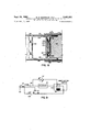
- FIGURE 4 That portion of the drive system which drives tray 25 is most clearly illustrated in FIGURE 4 wherein directly underneath the tray and substantially in line with platen 24, when in an imprinting position, is a power shaft 95 rotatable about bushings within the side walls of the unit 51. Equally spaced along the power shaft 95 integral and concentric therewith are four bearings 96 for supporting tray 25 at its downwardly protruding support areas 97. At the center of power shaft 95 is a gear 98 fixed for rotation therewith and meshed with a rack 99 also extending down from the tray.
- a pair of nylon elongated bars 101 are aflixed to side walls 22 and 23 to cooperate with grooves 102 located within the tray flanges which not only prevent substantial vertical movement, but also guide the tray relative to the main frame.
- FIGURES 1 and 2 in addition to FIGURE 4 show the extension of one end of power shaft 95 beyond the side of the printing machine, where it 103 which gear is meshed with gear 104 integrally secured to spur gear 105.
- Gears 104 and 105 are adapted for rotating motion about shaft 106.
- Pulley 107 is attached for rotatable motion about an axially movable thrust bearing 106, and is connected by way of belt 108 to a drive pulley 109 locked to the output shaft 111 of motor 112, the pulley system allowing for suitable speed reduction.
- Support 90 is employed for mounting motor 112 in a pivotal fashion by way of bar 113 extending through the motor and the sides of support 90.
- plunger 119 will be attracted to the solenoid (in the direction indicated by the arrow X) thereby urging thrust bearing 106 in a similar direction forcing the motor-driven pulley 107 in to overcome compression spring 116 bringing pin 115 into engagement with the spur-gear to thus drive tray 25 in the Y direction via power shaft 95 and gears 103, 104.
- FIGURES 3 and 4 Part of the apparatus utilized for accomplishing the tray return is disclosed in FIGURES 3 and 4 wherein a spring 122 is fastened at one end to an adjustable holder 123 which holder is regulated by a screw 124 secured to a plate 125. The remaining end of spring 122 is fastened to a cable 126 wrapped about a slightly tilted pulley 127 mounted to connecting bar 28 by way of a bracket 128, then the cable is fed back to be secured to the power shaft 95.
- the decelerating brake has been designed to ease tray 25 back into its at-rest positon.
- the mechanism for accomplishing the aforesaid decelerating brake action is shown in FIGURES 4 and 8 wherein the rear of tray 25 is provided with apertures 129 and 131 containing nylon plugs 132 and 133 respectively, the plugs being urged outwardly on a horizontal plane by springs 134.
- nylon elongated bars 101 each having an inclined plane designed so that the thickness of elongated bars 101 progressively increases from the rear toward the center of the printing machine.
- At the wider end of each of the elongated bars is one of a pair of indentures 137 and 138 accommodating the outer ends of respective nylon plugs 132, 133, as shown.
- stop piece 139 may also be employed to abut the rear inner side of the tray for further ensuring that the tray will be stopped at the position illustrated in FIGURE 1.
- FIGURE 8 there is shown a schematit: of an exemplary electrical system which may be used with the present invention, wherein a conventional three wire input plug 141 is connected through one lead to a fuse 142, thence to solenoid 121 and motor 112, the motor and solenoid further being tied to a common contact 142.
- the second lead of plug 141 is fed to a contact 143 by way of OFF-ON switch 144, the two contacts 143 and 142 being fastened in snap-action switch 91 adjacent plunger 93.
- FIGURE 1 a view of the tray 25 is disclosed in its rest position. After printing plates 21 and 22, representative of the information to be printed are placed on the corresponding anvils 31 and 32, a form-set is inserted under the open clamp 44 against stop pin 42 and between the shoulders 39 and 41.
- push button A is depressed as its mechanism had been adjusted to accommodate the selected form-set.
- sectional shaft 71 is forced rearwardly to actuate the snap-action switch 91 by way of link 88 as illustrated in FIGURE 6, thereby causing electrical current to actuate motor 112 and energize solenoid 121.
- Plunger 119 and thus rod 118 will be attracted toward the solenoid meshing spur-gear 105 with pulley 107 to drive the power shaft 95 which in turn drives tray 25.
- a machine comprising a base, a tray at least a portion thereof forming a plane which defines a print bed, a carriage mounted on said base, said tray supported for reciprocating travel on said base relative to the carriage, a platen assembly mounted on the carriage and adapted to be impelled into one of two or more printing positions with respect to the print bed, a platen rotatably mounted on said platen assembly, means for selecting one of said positions to be assumed by said platen assembly for a subsequent imprint stroke, means for impelling said platen assembly into the selected one of said printing positions when the tray is moved in a first direction during an imprinting stroke and for elevating the platen assembly from the print bed into a non-printing position when the tray is moved in a second direction opposite to the first during a return stroke.
- the combination recited in claim 1 including means for driving said tray in the first direction, said selecting means comprising means to activate the drive means.
- said selecting means comprises separate depressable buttons for each one of said printing positions.
- said activating means comprises a switch adapted to be engaged through any one of said depressable buttons.
- the combination recited in claim 2 including spring return means, said platen assembly elevating means adapted to disengage the drive means allowing said spring return means to move the tray in the second direction for a return stroke.
- the combination recited in claim 1 including a reference surface displaced from the print bed and adapted to be engaged by said platen assembly when in any one of said printing positions, means for separately adjusting each one of said printing positions relative to the reference surface.
- a machine comprising a base, a tray at least a portion thereof forming a plane which defines a print bed, a carriage secured to said base, said tray supported for reciprocating travel on said base, a platen assembly mounted on the carriage for rockable movement thereabout into one of two or more printing positions with respect to the print bed, a platen rotatably mounted on said platen assembly, separate selective means corresponding to each one of said printing positions for choosing one of said positions to be assumed by the platen assembly for a subsequent imprinting stroke, camrned means for rocking and maintaining said platen assembly into the selected one of said printing positions when the tray is moved in a first direction during an imprinting stroke and for rocking the platen roller into an elevated nonprinting position from the printing bed when the tray is moved in a second direction opposite to the first during a return stroke, means for driving said tray in the first direction, a switch for activating said drive means, and each one of said selective means
- the combination recited in claim 8 including spring return means adapted to be energized while the tray is being driven in the first direction, said platen assembly elevating means adapted to disengage the drive means allowing said spring return means to move the tray in the second direction for a return stroke.
- the combination recited in claim 8 including a reference surface displaced from the print bed and adapted to be engaged by said platen assembly when rocked into any one of said printing positions, means for separately adjusting each one of said printing positions relative to the reference surface, and resilient means to bias said reference surface against said platen assembly when engaged therewith.
- a machine comprising a base, a tray at least a portion thereof forming a plane which defines a print bed, a carriage mounted on said base, said tray supported for reciprocating travel on said base and relative to the carriage, a platen assembly mounted on the carriage for rockable movement there- 'about into one of two or more printing positions and into a non-printing position with respect to the print bed, a roller platen rotatably mounted on said platen assembly, a separate selective push-button means corresponding to each one of said printing positions for choosing one of said positions to be assumed by the platen assembly for a subsequent imprinting stroke, a reference surface displaced from the print bed and adapted to be engaged by said platen assembly when rocked into any one of said printing positions, separate screw means in the platen assembly for adjusting each one of said printing positions relative to the reference surface when engaged therewith, a cammed surface on the tray, a torsion spring fixed to said platen assembly to coact
Landscapes
- Engineering & Computer Science (AREA)
- Mechanical Engineering (AREA)
- Handling Of Sheets (AREA)
Description
3,402,661 BED Sept. 24, 1968 w. P. BARBOUR ETAL CONTROL MEANS FOR TRAVELING PLATEN ROLLER IN AND CYLINDER PRINTING MACHINES Filed Oct. ll, 1965 5 Sheets-Sheet l R U 0 B R A B 8 M U n M W HARVEY L. COOK 9M PM p 1 68 w. P.BARBOUR ETAL 3,402,661 CONTROL MEANS FOR TRAVELING PLATEN ROLLER IN BED AND CYLINDER PRINTING MACHINES Filed Oct. 11, 1965 5 Sheets-Sheet 2 lliili lhiiihhillmlilllimm p 1963 w. P. BARBOUR ETAL 3,402,661
CONTROL MEANS FOR TRAVELING PLATEN ROLLER IN BED AND CYLINDER PRINTING MACHINES Filed om. 11, 1965 5 Sheets-Sheet :5
FIG.4
CONTROL MEANS IOR TRAVELING PLATEN ROLLER IN BED AND CYLINDER PRINTING MACHINES Filed Oct. 11, 1965 5 Sheets-Sheet 4 (LI l t. 3
ll lllll' llall Sept. 24, 1968 w P. BARBOUR ETAL 3,402,661
CONTROL MEANS FOR TRAVELING PLATEN ROLLER IN BED I AND CYLINDER PRINTING MACHINES Filed Oct. 11, 1965 5 Sheets-Sheet 5 L A r FIG. 8
M SNAP ACTION I4 42 l 2l SWITCH H1551 SOLENOID I 1 l42d '--hll OFF ON 90 93 T FIG. 9
United States Patent 0 CONTROL MEANS FOR TRAVELING PLATEN ROLLER IN BED AND CYLINDER PRINTING MACHINES William Plumb Barbour, Alexandria, and Harvey L. Cook, Jr., Falls Church, Va., assignors to Farrington Business Machines Corporation, Springfield, Va., a corporation of Massachusetts Filed Oct. 11, 1965, Ser. No. 494,815 12 Claims. (Cl. 101--269) ABSTRACT OF THE DISCLOSURE A printing machine is disclosed for use with portable printing means such as credit cards, the machine including a fixed base, a carriage mounted on the base, and a tray adapted for reciprocating travel on the base with respect to the carriage. The tray includes a print bed portion for receiving the credit card and any other suitable print elements. Mounted within the carriage is a platen assembly which may be impelled into one of a plurality of predetermined printing positions with respect to the print bed. The platen assembly, including a platen rotatably mounted thereon, is impelled into one of the predetermined printing positions when the tray is moved in a first direction during the imprinting stroke. It is then retracted to a non-printing positon when the tray is moved in the opposite direction during a return stroke.
The present invention relates to a printing machine and, more particularly, to an improved printing machine for recording data on documents from individual printing devices, of a kind suitable for use as identification tokens, by impressing a platen across the face of the document inserted between the path of the platen and the printing device.
Such printing machines are generally utilized in retail sales systems wherein sales are made on credit to enable data in possession of the individual to be printed upon a suitable sales record from which the individual may be later billed. Normally, the sales record comprises a single sheet or a form set having several copy sheets the thickness of the form set varying in accordance with the number of copy sheets which number of copy sheets may vary upon the particular transaction being made. In other cases the sales record might be fairly uniform and a few different types of known printing devices employed could vary in thickness. In printing systems of the type disclosed above, it is well known that in order to obtain uniform and optimum printing pressure on documents and printing devices having varied thicknesses, it is necessary to compensate for the difference in thickness encountered in performing each separate imprint operation.
The general purpose of this invention is to provide a novel printing machine which overcomes the above noted difilculties by automatically compensating for varying thicknesses among printing plates and/or sales documents. To accomplish the above function there is provided a printing machine which contemplates a simple yet efiicient means for automatically lowering the printing platen, prior to an imprint, into a chosen one of two or more imprinting positions, each position being spaced at a different distance from the print bed and having been pre-set in accordance with the thicknesses of the particular printing plates or sales forms to be used to obtain uniform and optimum printing pressure for producing a high quality imprint during each printing operation. Further provisions are made by using a platen mechanism having a resiliency which is common to each of the above printing positions allowing for additonal slight variations in printing plates, sales documents and/or the type height raised above the printing plate surface. The particular embodiment of the invention shown is electrically operated and automatically initiates the printing cycle operation simultaneously with the selection of any one of the roller platen printing positions.
Objects of the invention are toprovide a printing machine which produces clear cut and uniform printing, which operates conveniently and with little effort, which permits the roller platen during a printing operation to be automatically spaced at a chosen one of two or more pro-selected printing positions, and simultaneously upon selection of any one of the printing positions initiate the printing cycle for accomplishing a high quality imprint, and in addition which provides for collateral compensation to account for the slight additional thickness variations encountered by the roller platen during an imprint.
Other objects, advantages and capabilities of the present invention will become apparent from the following detailed description, taken in conjunction with the accompanying drawings, illustrating a preferred embodiment of the invention.
In the drawings:
FIGURE 1 is a front perspective view of an electrical imprinter constructed in accordance with the principles of the present invention.
FIGURE 2 is a plan view of the novel imprinter shown in FIGURE 1.
FIGURE 3 shows a side elevation of the imprinting machine taken on the line 33 of FIGURE 2.
FIGURE 4 is a cross sectional view of the machine taken along line 44 of FIGURE 3.
FIGURES 5 and 6 are sectional views of the platen roller assembly taken on the line 55 of FIGURE 4. at different points in time of travel by the tray 25 once an imprint cycle has been initiated.
FIGURE 7 is a sectional view of the platen roller assembly taken during a printing operation and disclosing a further improved version of the present invention.
FIGURE 8 is a sectional view of the machine disclosing a mechanism for positioning and braking the tray, taken on the line 8-8 of FIGURE 3.
FIGURE 9 is an electrical schematic diagram employed with the machine.
One form of the present invention is illustrated in FIGURE 1 as embodied in a motor-operated printing machine adapted to transfer impressions from printing plates 21 and 22, having raised-type characters, onto document copy or copies comprising a form set 23 which when placed in printing position overlies the printing plates. The form set 23 may be in the form of an eightycolumn or fifty-one column size with interlaced carbon sheets for producing multiple copies. A platen roller 24 is used for transferring information to the form set by means ofconstant printing pressure engagement with the raised type on the printing plate same when a movable tray 29, on which the printing plates and form set are placed, is impelled to travel under the platen roller. Although the platen roller described in the present invention is of the dry type being particularly adapted for use with carbon-type impression forms, a modified roller of the ink impregnated type, as disclosed in US. Patent No. 2,629,730 to Gilbert, may be employed.
Frame and tray The printing machine shown in FIGURES l, 2 and 3 comprises main frame 25 including pair of side walls 26 and 27 integrally connected at their mid-sections by a connecting bar 28 which extends between the entire length of the side walls. The upper portion of the frame 25 forms a U-shaped track which is adapted for enabling a tray 29 to slideably travel thereon in a controlled reciprocating motion as will hereinafter be described in detail. The four corners of the bottom area of tray 29 are provided with bearings 30 to minimize friction or enhance sliding action when the tray is travelling with respect to the main frame 25.
The exterior of the traveling tray bears a pair of anvils 31 and 32, which surfaces define a print bed plane, for supporting thereon printing plates 21 and 22 respectively. Between each anvil 31, 32 and the exterior of the tray are sheet guide members 33 and 34 each to each, enabling the printing plates to be properly positioned and secured upon the anvil surfaces. Adjacent anvil 32 is a further anvil 35 upon which may be located, by way of receiving pins 36, a printing plate indicating a dealer or user identification. Situated about the center but to oneside in tray 25 is a cavity 37 in which a date wheel 38 is seating by affixing the same to the underside of the tray in a suitable manner allowing for height adjustment of the same relative to the print bed plane. Shoulders 39 and 41 on the sides of tray 25 have several functions one of which is to allow for proper positioning of form sets 23 on the print bed plane. If desired shoulder 39 may be made adjustable so that the tray might accommodate form-sets having varying widths. A stop pin 42 neighboring platen 24, is used for positioning the attached front end of the form set on the tray.
As illustrated in FIGURES 1 and 3, directly beneath platen roller 24 yet attached to the traveling tray 25 is a clamp 44 of obtuse configuration having a pair of side ear portions 45 formed at right angles thereto about the center of each of the clamp sides. The side ear portions are intersected by and pivotable about one of a pair of pins 46, each pin being loosely secured within a cavity in the respective opposite sides of the tray 29 beneath the level of the print bed plane. The rear portion of the clamp 44, as shown in FIGURE 3, is urged upwardly by tension springs 47 seated within tray cut-outs 48 thus biasing the clamp in a clockwise direction about pivot pins 46 to press the forward end of the clamp against the friction coated surface of raised pedestal 43 for fastening a form set thereto. However, when the tray occupies the position shown in FIGURES 1 and 2, a stationary bar 49 will engage the rear end of the clamp to force the same in a counterclockwise direction about pivot pins 46 as viewed from FIGURE 3, thus allowing the forward end of the clamp to be sufficiently displaced above the pedestal 43 for receiving a form set therebetween.
Push-button actuator and platen adjustment When the operator depresses a selected one of the four buttons denoted as A, B, C, and D in FIGURE 1, he simultaneously energizes the drive mechanism and accurately establishes the proper clearance between the print bed plane anvils 31, 32 and platen roller 24 for a related form set thickness yet in each instance for an identical printing plate thickness, thus automatically allowing form sets of different thicknesses to be readily and clearly printed upon by merely selecting and depressing a selected button for a corresponding set form set thickness which may be easily predetermined. For example, the form sets employed differ only by the number of additional copy sheets and/ or carbon in the set therefore a system might be adapted so that the button depressed for the basic form set would be A, button B would be depressed when a form set incorporates an additional copy sheet, and so on.
The apparatus for accomplishing the above function, shown in FIGURES 3 and 4, is mainly located within the inverted U-shaped unit 51 mounted by appropriate means to side walls 26 and 27 of main frame 25 to extend over an area traversed by the traveling tray. Within unit 51 is the two part platen roller 24 separated by spacer 52 and rotatably set on shaft 53, which shaft is received through the lower portions of arms 54, 55 of a bracket assembly 56, to lie about an axis parallel to the print bed plane. The entire bracket assembly 56 is supported for pivotable motion about a rod 57 secured to and extending across the unit 51. By use of suitable spacers on rod 57 the bracket assembly may be properly positioned for roller alignment with the anvil surfaces. Bracket assembly 56 further comprises a member 61 which in the preferred embodiment is a torsion spring fixed to arm 54 and protracted across the width of the bracket assembly to freely protrude through arm 55. At the outer side of arm 55 the torsion spring is bent at approximately a ninety degree angle to form a leg encased in a nylon shoe 62 the lower edge of which extends downwardly towards the tray surface 29 and below the upper surface of shoulder 41, the shoe being situated in a path traveled by the shoulder 41, which shoulder is co-extensive with the printing bed area, so as to engage the same in a cammed type action when the tray is driven under bracket assembly 56 during a printing operation for purposes which will hereinafter be explained.
The rearward end 63 of bracket assembly 56 may be described as the control end in that it contains four individually adjustable screws 64, 65, 66, and 67, each being provided with upwardly protruding latch ends for individually yet accurately controlling a pre-determined clearance between the print bed plane and the platen during an imprinting operation. Bracket assembly 56, in its normal inactivated state, will occupy the position shown in FIGURE 3 whereby the platen roller is at a non-printing elevation considerably displaced from the print bed plane allowing a form set to be easily placed thereunder. This non-printing position is normally maintained by the platen 24 as the off-center weight of the bracket assembly will cause it to rock about rod 57 in a counter-clockwise direction to abut the obstruction bar 50.
Located above the bracket assembly 56 is the pushbutton mechanism comprising a housing 68, illustrated in FIGURES 2 and 5, containing four separate narrow channels 69, each channel receiving one of four sectional shafts 71, 72, 73, and 74, which shafts are each fastened at their forward ends to push-buttons A, B, C, and D, respectively. Toward the forward ends of the shafts the cross-section of each of the channels 69 is slightly enlarged at for accommodating the push-buttons. To maintain the push-buttons in their outermost position toward the operator, compression springs 76 are inserted within the four enlarged channels 75 biased against pushbuttons A, B, C, D, as shown in FIGURES 2 and 5. The tailpiece of each sectional shaft 71-74 is indented to form a catch adapted for single selective engagement with the respective latch ends of adjustable screws 64, 65, 66, and 67. A common reference plane 82 is defined by the common lower surface of the sectional shafts 71-74 together for properly positioning the roller platen relative the print bed. When motion is imparted to the traveling tray by depressing a push-button A, B, C, or D the shoe 62 is subsequently engaged to ride over or follow in cam fashion the shoulder 41 thereby twisting the torsion spring 61 to rock the bracket assembly in a clockwise direction (as viewed from FIGURE 3) about rod 57 and forcing a selected one of the adjustable screw latch ends into engagement with the associated catch of the selected pushbutton (see FIGURE 6), and thus against reference plane 82. It is noted that each of the several printing positions assumed by platen 24 the bracket assembly arms 54, 55 dispose the platen roller over yet at an angle slightly to the left of a power shaft to provide for an improved print quality. The power shaft 95 drives the tray 25 under platen 24 during an imprinting operation to be hereinafter described in greater detail.
Therefore, the above-described mechanism by selective push buttons automatically provides a proper platento-print bed plane clearance for individually accommodating each of several selected form set thicknesses, given a standard printing plate thickness, for establishing uniform and optimum printing pressure. In addition, there may be provided a mechanism to compensate for utilizing printing plates of varied thickness while maintaining uniform and optimum printing pressure within a specified range of printing plate thickness variances.
To achieve the latter noted additional function, the preferred embodiment, as only appearing in FIGURES 1 and 7, discloses push button housing 68 pivotally mounted about a shaft 77 that is supported by unit 51, however yet limited the downward movement of housing 68 is limited by a lock screw 78 threaded within the housing. The upper rearward surface of housing 68 is grooved at 79 for a spring 80 seated therein, the spring extending through an aperture in unit 51 yet enclosed by a casing 81 partly situated within the aperture. Protruding through the top of casing 81 is an ad ustable set screw 82 having a bottom plate for regulating the spring force acting down upon housing 68. The set screw is generally adjusted in an imprint position to abut the housing 68 when using on an anvil (as adjustment CIlteria) a card thickness substantially equal to the minimum embossed printing plate thickness normally employed in combination with any one of the form sets, the proper push-button being depressed for the corresponding form set. The screw 78 is held in position, once set, by a rigid finger 83 tightly held by a screw 84, and adapted to lie within one of several grooves formed in the head of the set screw. Thus, by providing a spring 80 which exerts a uniform force when compressed, printing plates having slightly larger thicknesses can be accommodated by the compensating spring to provide uniform and optimum printing pressure. Thus, quality imprints may be obtained when simultaneously utilizing printing plates and form sets of varying thicknesses.
There is shown in FIGURES 4, 5 and 6 to the rear of frame 51 a link 88 swingable about pivot members 89 secured to each side of the frame 51. To the rear of and in line with the pivotal path traveled by one leg of link 88 is a snap-action switch 91, mounted on support 90, comprising a pivoted roller level 92 normally biased outwardly by a spring tensioned plunger 93 as illustrated in FIGURE 3. In line with the upper horizontal bar link 88 are the ends of sectional shafts 71, 72, 73, and 74, whereby when any one of the buttons A, B, C, or D is pushed the respective sectional shaft will engage the link 88 to force the same backward and depress plunger 93 by way of lever 92 activating snap-action switch 91. In order to prevent any twisting of the link 88 when button D is pushed a brace 94 is fastened by. suitable means to unit 51 for balancing the far end of the link.
A partial disclosure of the operation of the action of shoe 62 relative to shoulder 41 on traveling tray 29 at the end of an imprint cycle may now be clearly disclosed with reference to FIGURE 5. As the right end of the cammed shoulder approaches the bottom edge of the shoe (as shown in broken lines), the shoe will fall off the shoulder thus freeing the twisted torsion spring 61 and allowing it to return to its normal state simultaneously rocking the associated bracket assembly into the position shown in solid form in FIGURE 5 thereby elevating platen 24 away from the print bed and disengaging any one of the previously depressed sectional shafts 71, 72, 73 or 74 to deactivate snap-action switch 91 as lever 92 will bias freed link 88 in the direction indicated by the arrow. Since switch 91 is deactivated, the motor driving the traveling tray will be de-energized and the tray will be returned (in a manner to be hereinafter disclosed) to its initial rest position as illustrated in FIG- URE 1. It is observed that the cammed shoulder 41 is substantially co-extensive with the printing field comprising anvils 31 and 32 thus providing uninterrupted print engagement by platen 24 with a form-set in the area overlying the printing plates.
Drive system That portion of the drive system which drives tray 25 is most clearly illustrated in FIGURE 4 wherein directly underneath the tray and substantially in line with platen 24, when in an imprinting position, is a power shaft 95 rotatable about bushings within the side walls of the unit 51. Equally spaced along the power shaft 95 integral and concentric therewith are four bearings 96 for supporting tray 25 at its downwardly protruding support areas 97. At the center of power shaft 95 is a gear 98 fixed for rotation therewith and meshed with a rack 99 also extending down from the tray. To maintain rack 99 in downward driving engagement with gear 98 a pair of nylon elongated bars 101 are aflixed to side walls 22 and 23 to cooperate with grooves 102 located within the tray flanges which not only prevent substantial vertical movement, but also guide the tray relative to the main frame.
FIGURES 1 and 2 in addition to FIGURE 4 show the extension of one end of power shaft 95 beyond the side of the printing machine, where it 103 which gear is meshed with gear 104 integrally secured to spur gear 105. Gears 104 and 105 are adapted for rotating motion about shaft 106. Pulley 107 is attached for rotatable motion about an axially movable thrust bearing 106, and is connected by way of belt 108 to a drive pulley 109 locked to the output shaft 111 of motor 112, the pulley system allowing for suitable speed reduction. Support 90 is employed for mounting motor 112 in a pivotal fashion by way of bar 113 extending through the motor and the sides of support 90. Through connecting spring 114 the motor is biased toward the rear of the support allowing for sufiicient tension to satisfactorily drive belt 108 via pulley 109. Integral with yet protruding at a right angle from one side of driven pulley 107 is a pin 115 adapted for engagement with spur gear 105, however, the spur gear is normally maintained out of engagement with the pulley due to a compression spring 116 interposed between the spur gear and the driven pulley. To overcome the compression spring 116, a rod 118 is pivotally fastened at one end to unit 51, passed through a slot 117 at the end of thrust bearing 106, and secured at its remaining end to plunger 119 of a solenoid 121 mounted on support 90. Thus, when motor 112 and solenoid 121 are electrically activated, plunger 119 will be attracted to the solenoid (in the direction indicated by the arrow X) thereby urging thrust bearing 106 in a similar direction forcing the motor-driven pulley 107 in to overcome compression spring 116 bringing pin 115 into engagement with the spur-gear to thus drive tray 25 in the Y direction via power shaft 95 and gears 103, 104.
As previously disclosed toward the end of the description relating to the push button actuator and platen adjustment, when tray 29 has been driven forward by motor 112 to the extent that the entire print bed area has passed under roller platen 24, shoe 62 will fall off cammed shoulder 41 allowing the bracket assembly 56 to rock into a non-imprinting position thereby deactivating the snap-action switch 91 and de-energizing the motor 112, whereby the tray, by way of a spring-powered mechanism and brake system, will be safely returned to its initial rest position as shown in FIGURES 1 and 2.
Part of the apparatus utilized for accomplishing the tray return is disclosed in FIGURES 3 and 4 wherein a spring 122 is fastened at one end to an adjustable holder 123 which holder is regulated by a screw 124 secured to a plate 125. The remaining end of spring 122 is fastened to a cable 126 wrapped about a slightly tilted pulley 127 mounted to connecting bar 28 by way of a bracket 128, then the cable is fed back to be secured to the power shaft 95. Consequently as the power shaft is driven in a first direction of rotation by motor 112 to move tray 25, cable 126 is wound about power shaft 95 to tension the spring 122; therefore, when motor 112 is de-energized, the wound cable by way of the tensioned spring 122 will cause the power shaft 95 to rotate in a second direction is tied to a large gear opposite to the first returning the tray to its initial rest position. Screw 124 is provided to adjust the proper tension of spring 122.
In order to prevent the stored energy in tensioned spring 122 from slamming back tray with a force that might cause harm to a person operating the device, the decelerating brake has been designed to ease tray 25 back into its at-rest positon. The mechanism for accomplishing the aforesaid decelerating brake action is shown in FIGURES 4 and 8 wherein the rear of tray 25 is provided with apertures 129 and 131 containing nylon plugs 132 and 133 respectively, the plugs being urged outwardly on a horizontal plane by springs 134. At the same horizontal level with the spring-urged plugs, but fastened to each of side walls 22 and 23 toward the back of the printing device are nylon elongated bars 101 each having an inclined plane designed so that the thickness of elongated bars 101 progressively increases from the rear toward the center of the printing machine. At the wider end of each of the elongated bars is one of a pair of indentures 137 and 138 accommodating the outer ends of respective nylon plugs 132, 133, as shown. The braking action takes place when the tray 25 is rushing back to its reset position due to the tension of spring 122, in that the nylon plugs will encounter the increasing thickness of the elongated bars (see position of tray shown in broken lines at 130) causing an increasing drag on the tray and finally stopping the tray as the biased nylon plugs snap within indentures 137 and 138. If desired, a
stop piece 139 may also be employed to abut the rear inner side of the tray for further ensuring that the tray will be stopped at the position illustrated in FIGURE 1.
Electrical circuitry Referring now to FIGURE 8 there is shown a schematit: of an exemplary electrical system which may be used with the present invention, wherein a conventional three wire input plug 141 is connected through one lead to a fuse 142, thence to solenoid 121 and motor 112, the motor and solenoid further being tied to a common contact 142. The second lead of plug 141 is fed to a contact 143 by way of OFF-ON switch 144, the two contacts 143 and 142 being fastened in snap-action switch 91 adjacent plunger 93. When plunger 93 is depressed by lever 92 denoting that the platen roller is in proper printing positon, snap-action switch 91 is closed and will form a path to supply current to actuate motor 112 and solenoid 121 for driving tray 25 under the platen roller.
Operation The operation of the present invention may best be illustrated by first referring to FIGURE 1, wherein a view of the tray 25 is disclosed in its rest position. After printing plates 21 and 22, representative of the information to be printed are placed on the corresponding anvils 31 and 32, a form-set is inserted under the open clamp 44 against stop pin 42 and between the shoulders 39 and 41.
The operator will then depress one of four push buttons A, B, C, or D depending upon which push button mechanism has been pre-adjusted to accommodate the thickness of the particular form-set selected being used. For convenience, we shall say that push button A is depressed as its mechanism had been adjusted to accommodate the selected form-set. As the push button A is depressed sectional shaft 71 is forced rearwardly to actuate the snap-action switch 91 by way of link 88 as illustrated in FIGURE 6, thereby causing electrical current to actuate motor 112 and energize solenoid 121. Plunger 119 and thus rod 118 will be attracted toward the solenoid meshing spur-gear 105 with pulley 107 to drive the power shaft 95 which in turn drives tray 25.
As the tray travels rearwardly clamp 44 will be free of rod 49 allowing tension springs 47 to urge the clamp in a clockwise direction (see FIGURES 3 and 6) against the form-set for fastening the same to the top of the tray. Further travel of the tray will bring the the shoe 62 into engagement with and then upon the cammed shoulder 41 causing the twisted torsion spring 61 to rock bracket assembly 56 until the latch end of pre-adjusted screw 67 abuts the surface 82 of the depressed sectional shaft 71 and is caught by its catch at which point roller platen 24 has been brought into a proper printing position establishing the proper clearance from the printing bed in accordance with that thickness of a basic printing plate and the selected form-set employed. When a basic printing plate is utilized and an imprint operation is taking place, spring (see FIGURE 7) will not be compressed, but merely tensioned, if the initial adjustment had been properly performer; however, should the printing plate employed be greater in thickness than the basic one, then during an imprint operation on that particular printing plate spring 80 will be slightly compressed in accordance with the increased thickness of the printing plate, to maintain uniform and optimum printing pressure. When the tray has completed a major portion of its travel beneath platen 24, shoe 62 will fall off the end of cammed shoulder 41, as disclosed in 5, allowing the off-center weight of bracket assembly 56 to rock the same from the broken line to the solid line position, whereat roller platen 24 is elevated above the embossed printing plate and form-set. Therefore, snap-action switch 91 has been cut-off due to the fact that sectional shaft 71 when detached from latch 67, will be biased to its original position by spring 76 relieving the rearwardly acting force against link 88.
Once the motor 112 and solenoid 121 have been deenergized, the tensioned spring wound about drive shaft in co-operation with the decelerating brake action heretofore explained, will safely urge the tray back to its initial position where spring biased nylon plugs 132 and 133 will respectively snap into aperatures 129 and 131.
It should be understood, of course, that the foregoing disclosure relates to only a preferred embodiment of the invention and that numerous modifications or alterations may be made therein without departing from the spirt and the scope of the invention, it is desired therefore, that only such limitations be placed on the invention as are imposed by the prior are and as set forth in the appended claims.
We claim:
1. In the art of printing machines of the type adapted to use portable printing means, a machine comprising a base, a tray at least a portion thereof forming a plane which defines a print bed, a carriage mounted on said base, said tray supported for reciprocating travel on said base relative to the carriage, a platen assembly mounted on the carriage and adapted to be impelled into one of two or more printing positions with respect to the print bed, a platen rotatably mounted on said platen assembly, means for selecting one of said positions to be assumed by said platen assembly for a subsequent imprint stroke, means for impelling said platen assembly into the selected one of said printing positions when the tray is moved in a first direction during an imprinting stroke and for elevating the platen assembly from the print bed into a non-printing position when the tray is moved in a second direction opposite to the first during a return stroke.
2. In the art of printing machines of the type adapted to use portable printingmeans, the combination recited in claim 1 including means for driving said tray in the first direction, said selecting means comprising means to activate the drive means.
3. In the art of printing machines of the type adapted to use portable printing means, the combination recited in claim 2 wherein said selecting means comprises separate depressable buttons for each one of said printing positions.
4. In the art of printing machines of the type adapted to use portable printing means, the combination recited in claim 3 wherein said activating means comprises a switch adapted to be engaged through any one of said depressable buttons.
5. In the art of printing machines of the type adapted to use portable printing means, the combination recited in claim 2 including spring return means, said platen assembly elevating means adapted to disengage the drive means allowing said spring return means to move the tray in the second direction for a return stroke.
6. In the art of printing machines of the type adapted to use portable printing means, the combination recited in claim 1 including a reference surface displaced from the print bed and adapted to be engaged by said platen assembly when in any one of said printing positions, means for separately adjusting each one of said printing positions relative to the reference surface.
7. In the art of printing machines of the type adapted to use portable printing means the combination recited in claim 6 wherein resilient means are provided to bias said reference surface against said platen assembly when engaged therewith.
'8: In the art of printing machines of the type adapted to use portable printing means, a machine comprising a base, a tray at least a portion thereof forming a plane which defines a print bed, a carriage secured to said base, said tray supported for reciprocating travel on said base, a platen assembly mounted on the carriage for rockable movement thereabout into one of two or more printing positions with respect to the print bed, a platen rotatably mounted on said platen assembly, separate selective means corresponding to each one of said printing positions for choosing one of said positions to be assumed by the platen assembly for a subsequent imprinting stroke, camrned means for rocking and maintaining said platen assembly into the selected one of said printing positions when the tray is moved in a first direction during an imprinting stroke and for rocking the platen roller into an elevated nonprinting position from the printing bed when the tray is moved in a second direction opposite to the first during a return stroke, means for driving said tray in the first direction, a switch for activating said drive means, and each one of said selective means when employed adapted to actuate the switch.
9. In the art of printing machines of the type adapted to use portable printing means, the combination recited in claim 8 including spring return means adapted to be energized while the tray is being driven in the first direction, said platen assembly elevating means adapted to disengage the drive means allowing said spring return means to move the tray in the second direction for a return stroke.
10. In the art of printing machines of the type adapted to use portable printing means, the combination recited in claim 9, including means for braking the movement of said tray in the return stroke the effect of said braking means being progressively increased in the direction of the tray return.
11. In the art of printing machines of the type adapted to use portable printing means, the combination recited in claim 8 including a reference surface displaced from the print bed and adapted to be engaged by said platen assembly when rocked into any one of said printing positions, means for separately adjusting each one of said printing positions relative to the reference surface, and resilient means to bias said reference surface against said platen assembly when engaged therewith.
12. In the art of printing machines of the type adapted to use portable printing means, a machine comprising a base, a tray at least a portion thereof forming a plane which defines a print bed, a carriage mounted on said base, said tray supported for reciprocating travel on said base and relative to the carriage, a platen assembly mounted on the carriage for rockable movement there- 'about into one of two or more printing positions and into a non-printing position with respect to the print bed, a roller platen rotatably mounted on said platen assembly, a separate selective push-button means corresponding to each one of said printing positions for choosing one of said positions to be assumed by the platen assembly for a subsequent imprinting stroke, a reference surface displaced from the print bed and adapted to be engaged by said platen assembly when rocked into any one of said printing positions, separate screw means in the platen assembly for adjusting each one of said printing positions relative to the reference surface when engaged therewith, a cammed surface on the tray, a torsion spring fixed to said platen assembly to coact with the cammed surface for rocking and maintaining said platen assembly into the selected one of said printing positions when the tray is moved in a first direction during an imprintng stroke and for rocking the platen roller into the nonpnnting position when the tray is moved in a second direction opposite to the first during a return stroke, means for driving said tray in the first direction, a switch for activating said drive means, each of said push-buttons when depressed provided to actuate the switch for activating said drive means, spring return means adapted to be energized while the tray is being driven in the first direction, said means for rocking the platen assembly 1n a non-printing position adapted to disengage the drive means allowing said spring return means to move the tray in the second direction for a return stroke.
References Cited UNITED STATES PATENTS 2,043,600 6/1936 Ward 101-56 X 2,260,970 10/1941 Elder 101-96 2,994,265 8/1961 Hurlbut et a1 101-269 3,018,725 1/ 1962 Maul et a1 101-269 3,152,543 10/ 1964 Hanson et a1 101-269 3,283,711 11/1966 Lew 101-269 WILLIAM B. PENN, Primary Examiner.
Priority Applications (1)
| Application Number | Priority Date | Filing Date | Title |
|---|---|---|---|
| US494815A US3402661A (en) | 1965-10-11 | 1965-10-11 | Control means for traveling platen roller in bed and cylinder printing machines |
Applications Claiming Priority (1)
| Application Number | Priority Date | Filing Date | Title |
|---|---|---|---|
| US494815A US3402661A (en) | 1965-10-11 | 1965-10-11 | Control means for traveling platen roller in bed and cylinder printing machines |
Publications (1)
| Publication Number | Publication Date |
|---|---|
| US3402661A true US3402661A (en) | 1968-09-24 |
Family
ID=23966091
Family Applications (1)
| Application Number | Title | Priority Date | Filing Date |
|---|---|---|---|
| US494815A Expired - Lifetime US3402661A (en) | 1965-10-11 | 1965-10-11 | Control means for traveling platen roller in bed and cylinder printing machines |
Country Status (1)
| Country | Link |
|---|---|
| US (1) | US3402661A (en) |
Cited By (4)
| Publication number | Priority date | Publication date | Assignee | Title |
|---|---|---|---|---|
| US3656429A (en) * | 1970-11-02 | 1972-04-18 | Magnacheck Corp | Roller imprinter for pocket credit card |
| US3780669A (en) * | 1971-07-01 | 1973-12-25 | Farrington Business Mach | Imprinter having independently mounted, preloaded print rollers |
| US4793254A (en) * | 1988-02-12 | 1988-12-27 | Wright A Glenn | Document and card positioning device with spring releasable base |
| US20140291930A1 (en) * | 2012-08-09 | 2014-10-02 | Deq Systems Corp. | Card dealing shoe |
Citations (6)
| Publication number | Priority date | Publication date | Assignee | Title |
|---|---|---|---|---|
| US2043600A (en) * | 1929-12-12 | 1936-06-09 | Edward J Ward | Printing machine |
| US2260970A (en) * | 1938-06-04 | 1941-10-28 | Ncr Co | Impression mechanism |
| US2994265A (en) * | 1959-03-25 | 1961-08-01 | Douglas H Hurlbut | Card printing machine |
| US3018725A (en) * | 1960-02-10 | 1962-01-30 | Addressograph Multigraph | Printing machines |
| US3152543A (en) * | 1962-05-07 | 1964-10-13 | Pitney Bowes Inc | Pivotal carriage for traveling roller platens |
| US3283711A (en) * | 1964-05-25 | 1966-11-08 | Farrington Business Mach | Printing roller vertical position control device |
-
1965
- 1965-10-11 US US494815A patent/US3402661A/en not_active Expired - Lifetime
Patent Citations (6)
| Publication number | Priority date | Publication date | Assignee | Title |
|---|---|---|---|---|
| US2043600A (en) * | 1929-12-12 | 1936-06-09 | Edward J Ward | Printing machine |
| US2260970A (en) * | 1938-06-04 | 1941-10-28 | Ncr Co | Impression mechanism |
| US2994265A (en) * | 1959-03-25 | 1961-08-01 | Douglas H Hurlbut | Card printing machine |
| US3018725A (en) * | 1960-02-10 | 1962-01-30 | Addressograph Multigraph | Printing machines |
| US3152543A (en) * | 1962-05-07 | 1964-10-13 | Pitney Bowes Inc | Pivotal carriage for traveling roller platens |
| US3283711A (en) * | 1964-05-25 | 1966-11-08 | Farrington Business Mach | Printing roller vertical position control device |
Cited By (5)
| Publication number | Priority date | Publication date | Assignee | Title |
|---|---|---|---|---|
| US3656429A (en) * | 1970-11-02 | 1972-04-18 | Magnacheck Corp | Roller imprinter for pocket credit card |
| US3780669A (en) * | 1971-07-01 | 1973-12-25 | Farrington Business Mach | Imprinter having independently mounted, preloaded print rollers |
| US4793254A (en) * | 1988-02-12 | 1988-12-27 | Wright A Glenn | Document and card positioning device with spring releasable base |
| US20140291930A1 (en) * | 2012-08-09 | 2014-10-02 | Deq Systems Corp. | Card dealing shoe |
| US9452348B2 (en) * | 2012-08-09 | 2016-09-27 | Deq Systems Corp. | Card dealing shoe |
Similar Documents
| Publication | Publication Date | Title |
|---|---|---|
| US3260199A (en) | Platen mechanism for printing machines | |
| US2176371A (en) | Plate-printing device | |
| US3673960A (en) | Traveling cylinder printer with platen roller driven in closed path | |
| US3152543A (en) | Pivotal carriage for traveling roller platens | |
| US3402661A (en) | Control means for traveling platen roller in bed and cylinder printing machines | |
| GB483665A (en) | Improvements in or relating to printing mechanism, applicable to statistical and like machines | |
| US4037535A (en) | High speed printing apparatus | |
| US3447457A (en) | Card reader imprinter and/or reader mechanism | |
| US3277822A (en) | Printing machines | |
| US3232230A (en) | Traveling roller carriage means in bed and cylinder printers | |
| US4085675A (en) | Automatic electrical credit-card imprinter | |
| US3420171A (en) | Data recorder with swingable bed | |
| US4015700A (en) | Tape advance mechanism | |
| US3408931A (en) | Portable ticket printer | |
| EP0207127A1 (en) | Dot matrix printer. | |
| US2283804A (en) | Card printing machine | |
| US3653323A (en) | Card positioning and printing unit for credit card reading and imprinting equipment | |
| US3183834A (en) | Bed and cylinder tape printing machine | |
| US2874632A (en) | Check printing and punching machine | |
| US5062361A (en) | Credit card imprinter with one-piece slider | |
| US3280739A (en) | Printing device | |
| US3824922A (en) | Variable input data recorder | |
| US3173362A (en) | Bed and cylinder printer having axially shiftable guides on traveling cylinder | |
| US3349885A (en) | Type bar drive composed of two different components | |
| US4655132A (en) | Electrically powdered imprinter |