US3402655A - Blast protected ventilation duct system - Google Patents
Blast protected ventilation duct system Download PDFInfo
- Publication number
- US3402655A US3402655A US620213A US62021367A US3402655A US 3402655 A US3402655 A US 3402655A US 620213 A US620213 A US 620213A US 62021367 A US62021367 A US 62021367A US 3402655 A US3402655 A US 3402655A
- Authority
- US
- United States
- Prior art keywords
- duct
- blast
- bypass duct
- bypass
- blast wave
- Prior art date
- Legal status (The legal status is an assumption and is not a legal conclusion. Google has not performed a legal analysis and makes no representation as to the accuracy of the status listed.)
- Expired - Lifetime
Links
Images
Classifications
-
- A—HUMAN NECESSITIES
- A62—LIFE-SAVING; FIRE-FIGHTING
- A62B—DEVICES, APPARATUS OR METHODS FOR LIFE-SAVING
- A62B13/00—Special devices for ventilating gasproof shelters
-
- Y—GENERAL TAGGING OF NEW TECHNOLOGICAL DEVELOPMENTS; GENERAL TAGGING OF CROSS-SECTIONAL TECHNOLOGIES SPANNING OVER SEVERAL SECTIONS OF THE IPC; TECHNICAL SUBJECTS COVERED BY FORMER USPC CROSS-REFERENCE ART COLLECTIONS [XRACs] AND DIGESTS
- Y10—TECHNICAL SUBJECTS COVERED BY FORMER USPC
- Y10S—TECHNICAL SUBJECTS COVERED BY FORMER USPC CROSS-REFERENCE ART COLLECTIONS [XRACs] AND DIGESTS
- Y10S454/00—Ventilation
- Y10S454/902—Air raid shelter ventilation
Definitions
- a ventilation duct system which is capable of closing off a ventilation duct without any bypass of a blast wave from an outside explosion, such as that from an atomic bomb.
- the invention utilizes a main ventilation duct, a bypass ventilation duct, and a closure valve means Within the bypass duct and responsive to a blast wave introduced through the main duct.
- the length of the bypass duct is such that the blast wave in the main duct closes the valve means prior to arrival of the blast wave in the bypass duct.
- a bomb shelter will receive its source of air from outside the shelter up until the time of a blast from a nuclear bomb.
- a shelter of this type requires ventilation ducts which can be immediately closed off upon the occurrence of an explosion to protect inhabitants from injurious high pressure effects.
- a nuclear blast can produce a pressure in the order of 100 p.s.i. for a duration of several seconds. It is the initial or frontal blast Wave which must be kept from entering the shelter.
- Previous closure devices for shelter ventilation systems may be broadly divided into two types: one type which is light or heat sensitive to an atomic blast for closing a ventilation valve; and the other type being responsive to the initial blast wave for closing such valve.
- the present invention provides a simply constructed blast actuated ventilation system which will meet this need in the art by closing off a ventilation duct prior to arrival of the initial blast wave.
- An upstream end of the bypass duct is connected at an intermediate location to the main duct and a downstream end of the main duct is connected to an intermediate loca tion of the bypass duct.
- the valve means is located at the latter location.
- the length of the bypass duct between its connections to the main duct is to be such that the blast wave in the main duct arrives at the valve location prior to arrival of the bypass duct blast wave at such valve location. In this manner the bypass duct can be used to ventilate a shelter and yet be completely closed off before arrival of the initial shock Wave.
- An object of the present invention is to provide a blast protected ventilation duct system which is capable of "Ice closure prior to the entrance of an initial blast wave within a shelter.
- Another object is to provide a blast protected ventilation duct system which responds to an initial shock wave to close otf the system and yet will prevent the introduction of any portion of the initial blast wave within an attendant shelter.
- a further object is to provide a blast protected ventilation duct system which can be constructed entirely of mechanical components and which can be used repeatedly to prevent any portion of a blast wave from entering an attendant shelter even though the blast wave may be in the order of p.s.i. with a duration of several seconds.
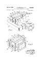
- FIG. 1 is an isometric view of the present blast protected ventilation duct system
- FIG. 2 is an isometric view of the duct system with the bypass duct and a major portion of the main duct removed;
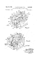
- FIG. 3 is an isometric view similar to FIG. 2 with portions cut away to illustrate various details and with the valve means in an open position;
- FIG. 4 is an isometric view similar to FIG. 2 with portions cut away to illustrate still further details of the invention, and with the valve means in a closed position.
- FIG. 1 a blast protected ventilation duct system 10 which includes a main venti1ation duct 12 and a bypass ventilation duct 14.
- This ventilation system is subject to receiving ventilation air :and a blast or shock wave of a nuclear explosion from the direction shown by the arrows in FIG. 1.
- the main ventilation duct 12 has upstream and downstream ends 16 and 18 respectively, :and the bypass ventilation duct 14 has upstream and downstream ends 20 and 22 respectively.
- the ducts 12 and 14 may be constructed of sheet metal and may be rectangular as seen in cross section, however their construction should be of sufficient strength to withstand the overpressures caused by the blast wave.
- a means may be provided for connecting the upstream end 20 of the bypass duct to the main duct 12 at a location intermediate the ends 16 and 18 of the main duct.
- This means may include a peripheral outwardly extending flange 24 which extends from the upstream end 20 of the bypass duct and bolt and nut combinations 26 which tightly engage this flange with the outer wall of the main duct 12.
- An opening (not shown) is provided in the main duct 12 at this connection of the bypass duct to the main duct so as to put them in communication with one another.
- a means, which is generally shown at 28, may be provided for connecting the downstream end 18 of the main duct to the bypass duct at a predetermined downstream location of the bypass duct, this predetermined location being generally shown at 30. This connection is for the purpose of introducing a blast wave from the main duct 12 at said predetermined location 30 within the bypass duct.
- the connecting means 28 may include a pair of similar side plates 32 and 34, front and rear box assemblies 36 and 38 respectively, and top and bottom similar box assemblies 40 and 42 respectively (see FIG. 2).
- the box assemblies 36,. 38, 40, and 42 may be rigidly connected at their upstanding flanges to the side plates 32 and 34 by a series of bolt and nut combinations 44.
- the front box assembly may be provided with an opening 46 for receiving the downstream end 18 of the main duct and these components may be rigidly connected together by any suitable means such as welding.
- the side plates 32 and 34 may be provided with openings 48, one of which is shown in FIG. .2, for providing a through passageway for the bypass duct 14.
- the bypass duct 14 may be connected to the side plate 32 by any suitable means such as a peripheral flange 50 and the bolt and nut com binations 44.
- the duct may be provided with flanges 52 at a separation plane of the duct, these flanges being held in tight engagement with one another by bolt and nut combinations 54.
- a valve means is mounted within the bypass duct at the predetermined location 30 and is responsive to the blast wave introduced by the main duct 12 for closing the bypass duct 14 to any passage of the blast wave. As shown in FIG. 1, the blast wave enters both the main duct 12 and the bypass duct 14 while the ventilation air is stopped at the connection of the bypass duct to the main duct and is routed into the bypass duct 14 for supplying air to a shelter (not shown) at the other end of the bypass duct.
- valve means 56 seal the bypass duct at the predetermined location 30 to prevent the blast wave within the main duct from entering the bypass duct at this location.
- the valve means 56 is responsive to the blast wave from the main duct 12 but will prevent the passage of any ventilation air from end 18 of the main duct.
- the valve means 56 is to allow the passage of ventilation air through the bypass duct 14 until the occurrence of a nuclear blast.
- the valve means is shown in its open position in FIG. 3 to allow the passage of ventilation air through the bypass duct 14, and is shown in its closed position in FIG. 4 to close off the bypass duct 14 to both the ventilation air and the initial blast wave traveling within the bypass duct 14.
- the valve means 56 will be described in more detail hereinafter.
- the blast wave in the main duct 12 close the bypass duct at location 30 before the initial shock wave in the bypass duct 14 arrives at such location.
- the main duct 12 may be straight throughout its entire length between its connection to the bypass duct at 20 and its downstream end 18, and the bypass duct 14 may be generally U shaped between its upstream end 20 and the predetermined location 30.
- bypass duct 14 with the additional length which is required to close the bypass duct prior to the arrival of the initial shock wave.
- any mechanical valve means 56 at the location 30 there will be a certain time lag in the closure of the valve after the arrival of the initial blast wave from the main duct 12 due to the inertia and friction of the valve components.
- the length of the bypass duct 14 is to be such that this inertia and friction of the valve components are overcome and the valve 56 is completely closed before the initial blast wave in the bypass duct 14 arrives at the location 30. Accordingly, in this manner the shelter at the other end of the bypass duct 14 will be completely protected from any blast effects.
- valve means 56 may include components which are similar to those described in a patent application entitled Pressure Actuated Valve, Ser. No. 552,644, filed by Harry L. Mason on May 24, 1966.
- the very significant advantage of the present invention over the apparatus described in this previous application is that no blast effects are allowed to enter the shelter during the closure of the valve means.
- the valve means 56 may include a pair of closure elements 58 and 60 which are pivoted at their ends by a pin 62 so as to cause a hinging action with respect to one another.
- the closure elements 58 and 60 are mounted within the bypass duct 14 and at the end of the main duct 12 with their pivotal axis freely translatable transverse to the bypass duct so that the closure elements are pivotable from an open upstream folded position (see FIG. 3) to a closed duct engaging downstream folded position (see FIG. 4).
- the closure elements 58 and 60 engage the bypass duct 14 within a transverse generally V shaped notch 64 which is provided in top and bottom plates 66 and 68 as well as a front plate 70 of the bypass duct 14. This notch then forms edges 72 in the top and bottom plates 66 and 68 for sealably engaging the closure elements 58 and 60 in their downstream folded positions, as seen in FIG. 4.
- the provision for maintaining the closure elements 58 and 69 in this upstream folded position prior to the occurrence of such an explosion may be a stop means and a biasing means which cooperate with the closure elements.
- the stop means may include an angle iron 74 which has one flange bolted to a bottom plate 76, the bottom plate 76 being integral with the bottom plate 68 of the bypass duct if desired.
- the biasing means may include a pair of plunger type cylindrical housed spring elements 80 and 82 which extend through side plates 32 and 34 respectively to engage the outer ends of the closure elements 58 and 60.
- the cylindrical portions of the spring elements 80 and 82 may be provided with offset flanges 84 which are bolted to the side plates 32 and 34.
- the cylindrical housings of the elements 80 and 82 may contain compression springs for biasing outwardly extending plungers 86 against the outer ends of the closure elements 58 and 60.
- closure elements 58 and 60 will be retained in their up- Stream folded position (as seen in FIG. 3) until the occurrence of an explosion at which time the initial blast wave will force the closure elements to a downstream folded position after which the spring elements 80 and 82 will quickly close the closure elements against the edges 72 (see FIG. 4).
- valve means 56 seal the bypass duct at location 30 from the downstream end 18 of the main duct 12. This is to prevent the entrance of any portion of the blast wave at location 30 while the valve means 56 is moving from its upstream folded position to its downstream folded position.
- a means for causing this sealing effect may include top and bottom pairs of plates and pins 87 and the pin 62 which cooperate with said pairs of plates.
- the pins 87 are connected at the outer ends of the closure elements 58 and 60 and extend both upwardly and downwardly from said closure elements.
- the pivot pin 62 extends both upwardly and downwardly from the closure elements.
- the pairs of plates 85 may each be triangular shaped, as shown in FIG.
- each of the pair of plates 85 may be provided with cutouts 88 for sealably and slidingly receiving the top and bottom extensions of the pins 87.
- Opposite sides of the top and bottom extensions of the pins 87 will sealably and slidingly engage the edges 72 of the top and bottom duct plates 66 and 68 respectively.
- the outer ends of the closure elements 58 and 60 may be rounded to sealably and slidingly engage beveled edges 90 of the front duct plate 70.
- the top and bottom edges 92 of the closure elements will make scalable and slidable engagement with the inwardly facing surfaces of the pairs of plates 85.
- the pairs of plates 85 may be held in a rigid assembly with respect to one another as well as with the top and bottom walls 66 and 68 by bolt and nut combinations 94 which extend through the top box assembly 40, as seen in FIG. 2, and a similar bottom box assembly which is not shown.
- valve means 56 Prior to the occurrence of a nuclear explosion the valve means 56 will be in its open position so as to allow passage of ventilation air through the bypass duct 14 to a shelter (not shown).
- a frontal or initial blast wave enters the main duct 12 and travels completely down the main duct as well as traveling within the bypass duct 14, as illustrated in FIG. 1.
- the valve means 56 will close, as shown in FIG. 4, due to the action of the' blast wave at the downstream end 18 of the main duct 12.
- the blast wave at the downstream end 18 of the main duct impinges upon the closure elements 58 and 60 in their upstream folded position, as seen in FIG.
- the arrangement of the present invention allows its components to be constructed of heavy materials so as to withstand extremely high blast overpressures,
- the material used for the majority of the components may be heavy sheet metal which may be designed to withstand overpressures in the order of 100 psi. for a duration of several seconds.
- the valve means 56 may be repeatedly used by recocking it to its upstream folded position, as shown in FIG. 3.
- the valve means 56 may be forced to this position by a probe which is used from the shelter to apply an upstream lever force to the valve means.
- a blast protected ventilation duct system comprising:
- a main ventilation duct which has upstream and downstream ends with respect to a blast wave;
- a bypass ventilation duct which has upstream and downstream ends with respect to said blast wave;
- valve means mounted within the bypass duct at said predetermined location and responsive to the blast wave introduced by the main duct for closing the bypass duct;
- the length of the bypass duct between its upstream end and said predetermined downstream location being sufiicient to cause the blast wave in the main duct to close the valve means prior to arrival of the blast wave in the bypass duct at said predetermined location.
- a blast protected ventilation duct system as claimed in claim 1 including:
- valve means connected to the bypass duct for sealing the valve means to passage of the blast wave introduced by the main duct as the valve means moves from its open position to its closed position.
- a blast protected ventilation duct system as claimed in claim 1 wherein:
- the main duct is straight throughout its entire length between its connection to the bypass duct and its downstream end;
- the bypass duct is U shaped between its upstream end and said predetermined location.
- valve means includes:
- closure elements being disposed with their pivotal axis freely translatable transverse to the bypass duct so that the closure elements are pivotable from an open upstream folded position to a closed duct engaging downstream folded position.
- valve means includes:
- bypass duct has a transverse V shaped notch to receive and sealably engage the closure elements in their downstream folded position.
- a blast protected ventilation duct system as claimed in claim 6 including:
- said plates being slotted to sealably receive said pins.
- the main duct is straight throughout its entire length between its connection to the bypass duct and its downstream end;
- the bypass duct is generally U shaped between its upstream end and said predetermined location.
Landscapes
- Health & Medical Sciences (AREA)
- General Health & Medical Sciences (AREA)
- Business, Economics & Management (AREA)
- Emergency Management (AREA)
- Air-Flow Control Members (AREA)
Description
BLAST PROTECTED VENTILATION DUCT SYSTEM Filed March 1, 1967 2 Sheets-Sheet l 1 N VENTOR 5 JOHN M. STEPHENSON BY DONALD E. WILLIAMS TQRNEY P 1968 J. M. STEPHENSON ETAL 3, 02,655
BLAST PROTECTED VENTILATION DUCT SYSTEM 2 Sheets-Sheet 2 Filed March 1, 1967 BLAST WAVE INVENTORS JOHN M. STEPHENSON DONALD E. WILLIAMS 5 United States Patent 3,402,655 BLAST PROTECTED VENTILATION DUCT SYSTEM John M. Stephenson, Camarillo, and Donald E. Williams,
Santa Barbara, Calil:'., assignors to the United States of America as represented by the Secretary of the Navy Filed Mar. 1, 1967, Ser. No. 620,213 9 Claims. (Cl. 98-119) ABSTRACT OF THE DISCLOSURE A ventilation duct system which is capable of closing off a ventilation duct without any bypass of a blast wave from an outside explosion, such as that from an atomic bomb. The invention utilizes a main ventilation duct, a bypass ventilation duct, and a closure valve means Within the bypass duct and responsive to a blast wave introduced through the main duct. The length of the bypass duct is such that the blast wave in the main duct closes the valve means prior to arrival of the blast wave in the bypass duct.
The invention described herein may be manufactured and used by or for the Government of the United States of America for governmental purposes without the payment of any royalties thereon or therefor.
The present thinking is that a bomb shelter will receive its source of air from outside the shelter up until the time of a blast from a nuclear bomb. A shelter of this type requires ventilation ducts which can be immediately closed off upon the occurrence of an explosion to protect inhabitants from injurious high pressure effects. A nuclear blast can produce a pressure in the order of 100 p.s.i. for a duration of several seconds. It is the initial or frontal blast Wave which must be kept from entering the shelter. Previous closure devices for shelter ventilation systems may be broadly divided into two types: one type which is light or heat sensitive to an atomic blast for closing a ventilation valve; and the other type being responsive to the initial blast wave for closing such valve. The latter type is preferable since these closure devices can be constructed of rugged mechanical components which are used repeatedly Without destruction by the initial blast wave. A serious disadvantage, however, of the blast actuated type closure device over the light sensitive devices is that due to the inertia of the mechanical components a portion of the blast wave will enter the shelter before the closure can be effected. There has been a need for a blast actuated type closure device which will close off the ventilation system prior to arrival of the initial blast wave in the ventilation duct.
The present invention provides a simply constructed blast actuated ventilation system which will meet this need in the art by closing off a ventilation duct prior to arrival of the initial blast wave. This has been accomplished by providing a main ventilation duct, a bypass ventilation duct, and a valve means mounted within the bypass duct for responding to the blast wave in the main duct so as to close the bypass duct prior to arrival of the blast wave. An upstream end of the bypass duct is connected at an intermediate location to the main duct and a downstream end of the main duct is connected to an intermediate loca tion of the bypass duct. The valve means is located at the latter location. The length of the bypass duct between its connections to the main duct is to be such that the blast wave in the main duct arrives at the valve location prior to arrival of the bypass duct blast wave at such valve location. In this manner the bypass duct can be used to ventilate a shelter and yet be completely closed off before arrival of the initial shock Wave.
An object of the present invention is to provide a blast protected ventilation duct system which is capable of "Ice closure prior to the entrance of an initial blast wave within a shelter.
Another object is to provide a blast protected ventilation duct system which responds to an initial shock wave to close otf the system and yet will prevent the introduction of any portion of the initial blast wave within an attendant shelter.
A further object is to provide a blast protected ventilation duct system which can be constructed entirely of mechanical components and which can be used repeatedly to prevent any portion of a blast wave from entering an attendant shelter even though the blast wave may be in the order of p.s.i. with a duration of several seconds.
Other objects, advantages and novel features of the invention will become apparent from the following detailed description of the invention when considered in conjunction with the accompanying drawings wherein:
FIG. 1 is an isometric view of the present blast protected ventilation duct system;
FIG. 2 is an isometric view of the duct system with the bypass duct and a major portion of the main duct removed;
FIG. 3 is an isometric view similar to FIG. 2 with portions cut away to illustrate various details and with the valve means in an open position;
FIG. 4 is an isometric view similar to FIG. 2 with portions cut away to illustrate still further details of the invention, and with the valve means in a closed position.
Referring now to the drawings wherein like reference numerals designate like or similar parts throughout the several views, there is shown in FIG. 1 a blast protected ventilation duct system 10 which includes a main venti1ation duct 12 and a bypass ventilation duct 14. This ventilation system is subject to receiving ventilation air :and a blast or shock wave of a nuclear explosion from the direction shown by the arrows in FIG. 1. With respect to the direction of the blast wave, the main ventilation duct 12 has upstream and downstream ends 16 and 18 respectively, :and the bypass ventilation duct 14 has upstream and downstream ends 20 and 22 respectively. The ducts 12 and 14 may be constructed of sheet metal and may be rectangular as seen in cross section, however their construction should be of sufficient strength to withstand the overpressures caused by the blast wave.
A means may be provided for connecting the upstream end 20 of the bypass duct to the main duct 12 at a location intermediate the ends 16 and 18 of the main duct. This means may include a peripheral outwardly extending flange 24 which extends from the upstream end 20 of the bypass duct and bolt and nut combinations 26 which tightly engage this flange with the outer wall of the main duct 12. An opening (not shown) is provided in the main duct 12 at this connection of the bypass duct to the main duct so as to put them in communication with one another.
A means, which is generally shown at 28, may be provided for connecting the downstream end 18 of the main duct to the bypass duct at a predetermined downstream location of the bypass duct, this predetermined location being generally shown at 30. This connection is for the purpose of introducing a blast wave from the main duct 12 at said predetermined location 30 within the bypass duct. The connecting means 28 may include a pair of similar side plates 32 and 34, front and rear box assemblies 36 and 38 respectively, and top and bottom similar box assemblies 40 and 42 respectively (see FIG. 2). The box assemblies 36,. 38, 40, and 42 may be rigidly connected at their upstanding flanges to the side plates 32 and 34 by a series of bolt and nut combinations 44. The front box assembly may be provided with an opening 46 for receiving the downstream end 18 of the main duct and these components may be rigidly connected together by any suitable means such as welding. The side plates 32 and 34 may be provided with openings 48, one of which is shown in FIG. .2, for providing a through passageway for the bypass duct 14. The bypass duct 14 may be connected to the side plate 32 by any suitable means such as a peripheral flange 50 and the bolt and nut com binations 44. In order to provide for a quick disconnection of the main ventilation duct 12 from the connecting means 28, the duct may be provided with flanges 52 at a separation plane of the duct, these flanges being held in tight engagement with one another by bolt and nut combinations 54.
A valve means, generally shown at 56, is mounted within the bypass duct at the predetermined location 30 and is responsive to the blast wave introduced by the main duct 12 for closing the bypass duct 14 to any passage of the blast wave. As shown in FIG. 1, the blast wave enters both the main duct 12 and the bypass duct 14 while the ventilation air is stopped at the connection of the bypass duct to the main duct and is routed into the bypass duct 14 for supplying air to a shelter (not shown) at the other end of the bypass duct.
It is important that the valve means 56 seal the bypass duct at the predetermined location 30 to prevent the blast wave within the main duct from entering the bypass duct at this location. The valve means 56 is responsive to the blast wave from the main duct 12 but will prevent the passage of any ventilation air from end 18 of the main duct. On the other hand, however, the valve means 56 is to allow the passage of ventilation air through the bypass duct 14 until the occurrence of a nuclear blast. The valve means is shown in its open position in FIG. 3 to allow the passage of ventilation air through the bypass duct 14, and is shown in its closed position in FIG. 4 to close off the bypass duct 14 to both the ventilation air and the initial blast wave traveling within the bypass duct 14. The valve means 56 will be described in more detail hereinafter.
As indicated hereinabove it is essential that the blast wave in the main duct 12 close the bypass duct at location 30 before the initial shock wave in the bypass duct 14 arrives at such location. This has been accomplished by making the length of the bypass duct between its upstream end 20 and the predetermined downstream location long enough to cause the blast wave in the main duct 12 to close the valve means 56 prior to arrival of the initial blast wave in the bypass duct at said predetermined location 30. As shown in FIG. 1 the main duct 12 may be straight throughout its entire length between its connection to the bypass duct at 20 and its downstream end 18, and the bypass duct 14 may be generally U shaped between its upstream end 20 and the predetermined location 30. These configurations then provide the bypass duct 14 with the additional length which is required to close the bypass duct prior to the arrival of the initial shock wave. In the use of any mechanical valve means 56 at the location 30 there will be a certain time lag in the closure of the valve after the arrival of the initial blast wave from the main duct 12 due to the inertia and friction of the valve components. The length of the bypass duct 14 is to be such that this inertia and friction of the valve components are overcome and the valve 56 is completely closed before the initial blast wave in the bypass duct 14 arrives at the location 30. Accordingly, in this manner the shelter at the other end of the bypass duct 14 will be completely protected from any blast effects.
In the preferred embodiment of the invention the valve means 56 may include components which are similar to those described in a patent application entitled Pressure Actuated Valve, Ser. No. 552,644, filed by Harry L. Mason on May 24, 1966. The very significant advantage of the present invention over the apparatus described in this previous application is that no blast effects are allowed to enter the shelter during the closure of the valve means. The valve means 56 may include a pair of closure elements 58 and 60 which are pivoted at their ends by a pin 62 so as to cause a hinging action with respect to one another. The closure elements 58 and 60 are mounted within the bypass duct 14 and at the end of the main duct 12 with their pivotal axis freely translatable transverse to the bypass duct so that the closure elements are pivotable from an open upstream folded position (see FIG. 3) to a closed duct engaging downstream folded position (see FIG. 4). The closure elements 58 and 60 engage the bypass duct 14 within a transverse generally V shaped notch 64 which is provided in top and bottom plates 66 and 68 as well as a front plate 70 of the bypass duct 14. This notch then forms edges 72 in the top and bottom plates 66 and 68 for sealably engaging the closure elements 58 and 60 in their downstream folded positions, as seen in FIG. 4.
In the upstream folded position of the closure elements 58 and 60 (see FIG. 3) the ends pivoted at 62 will be slightly upstream from the opposite ends of the closure elements. This is the position before the occurrence of a nuclear explosion. The provision for maintaining the closure elements 58 and 69 in this upstream folded position prior to the occurrence of such an explosion may be a stop means and a biasing means which cooperate with the closure elements. The stop means may include an angle iron 74 which has one flange bolted to a bottom plate 76, the bottom plate 76 being integral with the bottom plate 68 of the bypass duct if desired. An upstanding flange of the angle iron 74 is located opposite the closure elements 58 and 60 and may be provided with a threaded bolt 78 for engaging the closure elements at their pivotal connection and stopping them in the upstream folded position. The biasing means may include a pair of plunger type cylindrical housed spring elements 80 and 82 which extend through side plates 32 and 34 respectively to engage the outer ends of the closure elements 58 and 60. The cylindrical portions of the spring elements 80 and 82 may be provided with offset flanges 84 which are bolted to the side plates 32 and 34. The cylindrical housings of the elements 80 and 82 may contain compression springs for biasing outwardly extending plungers 86 against the outer ends of the closure elements 58 and 60. Accordingly, the closure elements 58 and 60 will be retained in their up- Stream folded position (as seen in FIG. 3) until the occurrence of an explosion at which time the initial blast wave will force the closure elements to a downstream folded position after which the spring elements 80 and 82 will quickly close the closure elements against the edges 72 (see FIG. 4).
As stated hereinabove it is important that the valve means 56 seal the bypass duct at location 30 from the downstream end 18 of the main duct 12. This is to prevent the entrance of any portion of the blast wave at location 30 while the valve means 56 is moving from its upstream folded position to its downstream folded position. A means for causing this sealing effect may include top and bottom pairs of plates and pins 87 and the pin 62 which cooperate with said pairs of plates. The pins 87 are connected at the outer ends of the closure elements 58 and 60 and extend both upwardly and downwardly from said closure elements. In a like manner the pivot pin 62 extends both upwardly and downwardly from the closure elements. The pairs of plates 85 may each be triangular shaped, as shown in FIG. 3, and are spaced from one another within the V shaped notch 64 to sealably and slidingly receive the top and bottom extensions of the pivot pin 62. Forward corners of each of the pair of plates 85 may be provided with cutouts 88 for sealably and slidingly receiving the top and bottom extensions of the pins 87. Opposite sides of the top and bottom extensions of the pins 87 will sealably and slidingly engage the edges 72 of the top and bottom duct plates 66 and 68 respectively. The outer ends of the closure elements 58 and 60 may be rounded to sealably and slidingly engage beveled edges 90 of the front duct plate 70. The top and bottom edges 92 of the closure elements will make scalable and slidable engagement with the inwardly facing surfaces of the pairs of plates 85. The pairs of plates 85 may be held in a rigid assembly with respect to one another as well as with the top and bottom walls 66 and 68 by bolt and nut combinations 94 which extend through the top box assembly 40, as seen in FIG. 2, and a similar bottom box assembly which is not shown.
Operation Prior to the occurrence of a nuclear explosion the valve means 56 will be in its open position so as to allow passage of ventilation air through the bypass duct 14 to a shelter (not shown). Upon the occurrence of a nuclear explosion a frontal or initial blast wave enters the main duct 12 and travels completely down the main duct as well as traveling within the bypass duct 14, as illustrated in FIG. 1. Before the initial blast wave travels down bypass duct 14 and arrives at location 30 the valve means 56 will close, as shown in FIG. 4, due to the action of the' blast wave at the downstream end 18 of the main duct 12. The blast wave at the downstream end 18 of the main duct impinges upon the closure elements 58 and 60 in their upstream folded position, as seen in FIG. 3, and causes them to move in a downstream direction. As the closure elements 58 and 60 move in the downstream direction the upstream biasing force component of the spring elements 80 and 82 is overcome so as to cause the spring elements 80 and 82 to exert a downstream force component which quickly snaps the closure elements into sealable engagement with the bypass duct at the V notch 64. Due to the additional length of the bypass duct 14 these closure elements 58 and 60 effect complete closure of the bypass duct 14 at location 30 prior to arrival of the initial blast wave from the bypass duct. Because of the seal to blast pressure at the upstream side of the valve means 56 and the closure of the valve means prion to arrival of the initial blast wave from the bypass duct 14, the occupants within the shelter (not shown) will not be subjected to injurious blast effects while the valve means 56 is undergoing its closure operation.
The arrangement of the present invention allows its components to be constructed of heavy materials so as to withstand extremely high blast overpressures, The material used for the majority of the components may be heavy sheet metal which may be designed to withstand overpressures in the order of 100 psi. for a duration of several seconds. The valve means 56 may be repeatedly used by recocking it to its upstream folded position, as shown in FIG. 3. The valve means 56 may be forced to this position by a probe which is used from the shelter to apply an upstream lever force to the valve means.
Obviously many modifications and variations of the present invention are possible in the light of the above teachings. It is therefore to be understood that within the scope of the appended claims the invention may be practiced otherwise than as specifically described.
We claim:
1. A blast protected ventilation duct system comprising:
a main ventilation duct which has upstream and downstream ends with respect to a blast wave; a bypass ventilation duct which has upstream and downstream ends with respect to said blast wave;
means connecting the upstream end of the bypass duct to the main du ct at a location intermediate the ends of the main duct;
means connecting the downstream end of the main duct to the bypass duct at a predetermined downstream location of the bypass duct so that a blast wave will be introduced by the main duct at said predetermined location;
valve means mounted within the bypass duct at said predetermined location and responsive to the blast wave introduced by the main duct for closing the bypass duct; and
the length of the bypass duct between its upstream end and said predetermined downstream location being sufiicient to cause the blast wave in the main duct to close the valve means prior to arrival of the blast wave in the bypass duct at said predetermined location.
2. A blast protected ventilation duct system as claimed in claim 1 including:
means connected to the bypass duct for sealing the valve means to passage of the blast wave introduced by the main duct as the valve means moves from its open position to its closed position.
3. A blast protected ventilation duct system as claimed in claim 1 wherein:
the main duct is straight throughout its entire length between its connection to the bypass duct and its downstream end; and
the bypass duct is U shaped between its upstream end and said predetermined location.
4. A blast protected ventilation duct system as claimed in claim 1 wherein the valve means includes:
a pair of pivoted closure elements for sealably engaging and closing said bypass duct;
said closure elements being disposed with their pivotal axis freely translatable transverse to the bypass duct so that the closure elements are pivotable from an open upstream folded position to a closed duct engaging downstream folded position.
5. A blast protected ventilation duct system as claimed in claim 4 wherein the valve means includes:
means for engaging the closure elements and stopping their pivotable movement in a slightly upstream folded position; and
means for biasing said closure elements toward their pivotal connection so that when the closure elements are in the slightly upstream folded position they are retained by an upstream biasing force component until the introduced blast wave overcomes said force component so that the biasing means exerts a downstream force component to snap the closure elements into engagement with said bypass duct.
6. A blast protected ventilation duct system as claimed in claim 5 wherein:
the bypass duct has a transverse V shaped notch to receive and sealably engage the closure elements in their downstream folded position.
7. A blast protected ventilation duct system as claimed in claim 6 including:
means connected to the bypass duct for sealing the valve means to passage of the blast Wave introduced by the main duct as the closure elements move from their upstream folded position to their downstream folded position.
8. A blast protected ventilation duct system as claimed in claim 7 wherein the means for sealing the valve means includes:
pins extending from the closure elements at their ends and at the pivotal axis;
top and bottom plates connected to the bypass duct,
said plates being slotted to sealably receive said pins.
9. A blast protected ventilation duct system as claimed in claim 8 wherein:
the main duct is straight throughout its entire length between its connection to the bypass duct and its downstream end; and
the bypass duct is generally U shaped between its upstream end and said predetermined location.
References Cited UNITED STATES PATENTS 3,140,648 7/1964 Bergman et al. 98-119 3,232,208 2/1966 Maassen 98-119 ROBERT A. OLEARY, Primary Examiner.
M. A. ANTONAKAS, Assistant Examiner.
Priority Applications (1)
| Application Number | Priority Date | Filing Date | Title |
|---|---|---|---|
| US620213A US3402655A (en) | 1967-03-01 | 1967-03-01 | Blast protected ventilation duct system |
Applications Claiming Priority (1)
| Application Number | Priority Date | Filing Date | Title |
|---|---|---|---|
| US620213A US3402655A (en) | 1967-03-01 | 1967-03-01 | Blast protected ventilation duct system |
Publications (1)
| Publication Number | Publication Date |
|---|---|
| US3402655A true US3402655A (en) | 1968-09-24 |
Family
ID=24485036
Family Applications (1)
| Application Number | Title | Priority Date | Filing Date |
|---|---|---|---|
| US620213A Expired - Lifetime US3402655A (en) | 1967-03-01 | 1967-03-01 | Blast protected ventilation duct system |
Country Status (1)
| Country | Link |
|---|---|
| US (1) | US3402655A (en) |
Cited By (3)
| Publication number | Priority date | Publication date | Assignee | Title |
|---|---|---|---|---|
| US5540618A (en) * | 1994-10-28 | 1996-07-30 | National University Of Singapore | Passive attenuator for shelter protection against explosions |
| US20060065308A1 (en) * | 2004-09-29 | 2006-03-30 | Rogge Timothy J | Pressure relief door for air duct work |
| US11073300B2 (en) | 2016-09-13 | 2021-07-27 | Beth-El Zikhron Yaaqov Industries Ltd. | Blast valve utilizing an aerodynamically configured blade |
Citations (2)
| Publication number | Priority date | Publication date | Assignee | Title |
|---|---|---|---|---|
| US3140648A (en) * | 1959-03-04 | 1964-07-14 | Bergman Sten Gosta Ariel | Anti-blast valve |
| US3232208A (en) * | 1962-12-24 | 1966-02-01 | Ewers & Miesner Hartgusswerk | Valve for air raid shelter |
-
1967
- 1967-03-01 US US620213A patent/US3402655A/en not_active Expired - Lifetime
Patent Citations (2)
| Publication number | Priority date | Publication date | Assignee | Title |
|---|---|---|---|---|
| US3140648A (en) * | 1959-03-04 | 1964-07-14 | Bergman Sten Gosta Ariel | Anti-blast valve |
| US3232208A (en) * | 1962-12-24 | 1966-02-01 | Ewers & Miesner Hartgusswerk | Valve for air raid shelter |
Cited By (5)
| Publication number | Priority date | Publication date | Assignee | Title |
|---|---|---|---|---|
| US5540618A (en) * | 1994-10-28 | 1996-07-30 | National University Of Singapore | Passive attenuator for shelter protection against explosions |
| SG89998A1 (en) * | 1994-10-28 | 2002-07-23 | Univ Singapore | Passive attenuator for shelter protection against explosions |
| US20060065308A1 (en) * | 2004-09-29 | 2006-03-30 | Rogge Timothy J | Pressure relief door for air duct work |
| US7275560B2 (en) * | 2004-09-29 | 2007-10-02 | A.J. Manufacturing, Inc. | Pressure relief door for air duct work |
| US11073300B2 (en) | 2016-09-13 | 2021-07-27 | Beth-El Zikhron Yaaqov Industries Ltd. | Blast valve utilizing an aerodynamically configured blade |
Similar Documents
| Publication | Publication Date | Title |
|---|---|---|
| US3111133A (en) | Explosive actuated normally closed valve | |
| US3402655A (en) | Blast protected ventilation duct system | |
| US2712427A (en) | Impact type snap acting shut-off valve | |
| US4243349A (en) | Containers for goods | |
| US3358961A (en) | Explosively driven shutter type pressure release apparatus | |
| US3323531A (en) | Quick opening gate valve | |
| US3412755A (en) | Pressure actuated valve | |
| US3662670A (en) | Blast-actuated valve-closure system | |
| US3525350A (en) | Reusable hermetically sealed valve | |
| US5362028A (en) | High speed gate valve | |
| US5052494A (en) | Explosion suppression device | |
| US3373758A (en) | High speed gate valve | |
| US3327894A (en) | Tank closure device | |
| US2679860A (en) | Explosion belief valve | |
| US2924403A (en) | Actuator device | |
| US9528612B2 (en) | Explosion-proof sliding gate valve for blocking a fluid flow in a pipeline | |
| CN105521836A (en) | Low-air-pressure testing system | |
| US3545365A (en) | Closure for exhaust stack | |
| GB2054132A (en) | Improvements relating to damper systems for air/gas ducts | |
| US3129716A (en) | Explosive actuated valve | |
| US3739796A (en) | In-line explosion arrester | |
| US3561346A (en) | Blast actuated module valve | |
| US3059565A (en) | Anti-blast closure device | |
| US4457328A (en) | Combined positive seal and repetitive actuation isolation valve | |
| RU145207U1 (en) | EXPLOSIVE LOCALIZING CAMERA OF REUSABLE USE FOR DESTRUCTION OF NON-DISPOSABLE AMMUNITION |