US3401778A - Gear type pump or motor - Google Patents
Gear type pump or motor Download PDFInfo
- Publication number
- US3401778A US3401778A US597631A US59763166A US3401778A US 3401778 A US3401778 A US 3401778A US 597631 A US597631 A US 597631A US 59763166 A US59763166 A US 59763166A US 3401778 A US3401778 A US 3401778A
- Authority
- US
- United States
- Prior art keywords
- pump
- gear
- gears
- end plate
- motor
- Prior art date
- Legal status (The legal status is an assumption and is not a legal conclusion. Google has not performed a legal analysis and makes no representation as to the accuracy of the status listed.)
- Expired - Lifetime
Links
- 238000007789 sealing Methods 0.000 claims description 35
- 239000012530 fluid Substances 0.000 claims description 19
- 230000008859 change Effects 0.000 claims description 4
- 230000008878 coupling Effects 0.000 description 17
- 238000010168 coupling process Methods 0.000 description 17
- 238000005859 coupling reaction Methods 0.000 description 17
- 230000002706 hydrostatic effect Effects 0.000 description 17
- 239000002184 metal Substances 0.000 description 13
- 230000000694 effects Effects 0.000 description 6
- 238000007667 floating Methods 0.000 description 4
- 230000002093 peripheral effect Effects 0.000 description 4
- 238000010276 construction Methods 0.000 description 3
- 239000007788 liquid Substances 0.000 description 3
- 229920002449 FKM Polymers 0.000 description 2
- 238000004891 communication Methods 0.000 description 2
- 239000003921 oil Substances 0.000 description 2
- 238000005086 pumping Methods 0.000 description 2
- 230000000717 retained effect Effects 0.000 description 2
- 229920002994 synthetic fiber Polymers 0.000 description 2
- 208000036366 Sensation of pressure Diseases 0.000 description 1
- 230000002411 adverse Effects 0.000 description 1
- 239000003831 antifriction material Substances 0.000 description 1
- 230000005540 biological transmission Effects 0.000 description 1
- CUZMQPZYCDIHQL-VCTVXEGHSA-L calcium;(2s)-1-[(2s)-3-[(2r)-2-(cyclohexanecarbonylamino)propanoyl]sulfanyl-2-methylpropanoyl]pyrrolidine-2-carboxylate Chemical compound [Ca+2].N([C@H](C)C(=O)SC[C@@H](C)C(=O)N1[C@@H](CCC1)C([O-])=O)C(=O)C1CCCCC1.N([C@H](C)C(=O)SC[C@@H](C)C(=O)N1[C@@H](CCC1)C([O-])=O)C(=O)C1CCCCC1 CUZMQPZYCDIHQL-VCTVXEGHSA-L 0.000 description 1
- 238000004512 die casting Methods 0.000 description 1
- 230000001050 lubricating effect Effects 0.000 description 1
- 239000010687 lubricating oil Substances 0.000 description 1
- 238000005461 lubrication Methods 0.000 description 1
- 238000003754 machining Methods 0.000 description 1
- 239000000463 material Substances 0.000 description 1
- 230000004048 modification Effects 0.000 description 1
- 238000012986 modification Methods 0.000 description 1
- 210000001611 motor endplate Anatomy 0.000 description 1
- 230000001105 regulatory effect Effects 0.000 description 1
- 239000007787 solid Substances 0.000 description 1
- XLYOFNOQVPJJNP-UHFFFAOYSA-N water Substances O XLYOFNOQVPJJNP-UHFFFAOYSA-N 0.000 description 1
Images


Classifications
-
- F—MECHANICAL ENGINEERING; LIGHTING; HEATING; WEAPONS; BLASTING
- F04—POSITIVE - DISPLACEMENT MACHINES FOR LIQUIDS; PUMPS FOR LIQUIDS OR ELASTIC FLUIDS
- F04C—ROTARY-PISTON, OR OSCILLATING-PISTON, POSITIVE-DISPLACEMENT MACHINES FOR LIQUIDS; ROTARY-PISTON, OR OSCILLATING-PISTON, POSITIVE-DISPLACEMENT PUMPS
- F04C15/00—Component parts, details or accessories of machines, pumps or pumping installations, not provided for in groups F04C2/00 - F04C14/00
- F04C15/0003—Sealing arrangements in rotary-piston machines or pumps
- F04C15/0023—Axial sealings for working fluid
- F04C15/0026—Elements specially adapted for sealing of the lateral faces of intermeshing-engagement type machines or pumps, e.g. gear machines or pumps
-
- F—MECHANICAL ENGINEERING; LIGHTING; HEATING; WEAPONS; BLASTING
- F04—POSITIVE - DISPLACEMENT MACHINES FOR LIQUIDS; PUMPS FOR LIQUIDS OR ELASTIC FLUIDS
- F04C—ROTARY-PISTON, OR OSCILLATING-PISTON, POSITIVE-DISPLACEMENT MACHINES FOR LIQUIDS; ROTARY-PISTON, OR OSCILLATING-PISTON, POSITIVE-DISPLACEMENT PUMPS
- F04C2/00—Rotary-piston machines or pumps
- F04C2/08—Rotary-piston machines or pumps of intermeshing-engagement type, i.e. with engagement of co-operating members similar to that of toothed gearing
- F04C2/082—Details specially related to intermeshing engagement type machines or pumps
- F04C2/086—Carter
-
- F—MECHANICAL ENGINEERING; LIGHTING; HEATING; WEAPONS; BLASTING
- F16—ENGINEERING ELEMENTS AND UNITS; GENERAL MEASURES FOR PRODUCING AND MAINTAINING EFFECTIVE FUNCTIONING OF MACHINES OR INSTALLATIONS; THERMAL INSULATION IN GENERAL
- F16D—COUPLINGS FOR TRANSMITTING ROTATION; CLUTCHES; BRAKES
- F16D31/00—Fluid couplings or clutches with pumping sets of the volumetric type, i.e. in the case of liquid passing a predetermined volume per revolution
- F16D31/04—Fluid couplings or clutches with pumping sets of the volumetric type, i.e. in the case of liquid passing a predetermined volume per revolution using gear-pumps
Definitions
- This invention relates to an improved gear pump or gear motor, and in particular it relates to an improved end plate arrangement for a gear pump or motor.
- the gears and the gear shafts in the pump of the present invention are mounted very rigidly to assure that the gears will rotate about the same geometrical axis as much as possible.
- the shaft bearings are located outside of the pumping area and rows of needle bearings are provided between each shaft and its respective gear. This arrangement provides rigidity in an extremely compact space. Therefore, since the mass of this extremely rigid gear and shaft structure has been substantially reduced, the effects of centrifugal force on these elements will be reduced proportionally.
- an end plate which floats in a recess so that it can change its orientation freely (within predetermined limits) with a universal, or three dimensional, movement to maintain its alignment with the end of the gear at all times, even when the gear is moved away from its original geometrical axis by the unevenly applied forces.
- the end plate also includes a pressure means for exerting a force on the end plate urging the same towards the gear.
- This pressure means includes structure to compensate for the varying pressures applied to different portions of the end plate on the side thereof facing the gears.
- the structure of the gear pump or motor end plates is as follows.
- the gears and gear shafts are mounted compactly and rigidly within the gear pump or motor housing.
- annular recesses adapted to receive the end plates which are annular in shape. That is, there are four annular recesses, one at each end of each gear.
- the two annular recesses at the same end of the pump overlap in the area where the gear teeth mesh.
- the inner circumference of these annular recesses in the housing are spaced radially outwardly from the housing aperture through which the gear shafts pass. Therefore, the gear shafts are mounted independently of the end plates.
- a substantially annular shaped end plate is received in each of the four annular spaces.
- the floating universal movement of each end plate in its recess is provided in the following manner.
- a first sealing ring is mounted in a groove in the rear side of the annular end plate (that is, the side facing away from the gear). This ring performs two basic functions. First, it separates the rear side of the end plate into two sections for a reason to be discussed below. In addition, this sealing ring spaces the end plate from the bottom of the recess, thereby avoiding metal to metal contact between the rear of the end plate and the bottom of the recess.
- the outer circumference of the end plate also has a circumferential groove therein.
- a second sealing ring having a diameter larger than the depth of the groove is placed in this groove to space the outer circumference of the end plate from the outer circumference of the annular recess. Consequently metal to metal contact between the outer circumference of the end plate and the recess is avoided.
- the inner circumference of the end plate is of a diameter slightly larger than the inside diameter of the recess. Consequently, the maximum contact between the inner circumference of the end plate and recess will be a line contact which would occur when the end plate is perpendicular to the gear shaft axis. When the end plate tilts relative to the gear shaft axis, then the end plate will contact the inner circumference of the recess only at two points.
- the present invention provides an end plate which virtually floats within the recess having metal to metal contact with the recess at most along one axial line and at least at only two points on the inner circumferencial surfaces of the end plate and recess.
- the invention also includes means for providing pressure forces acting on the rear side of the end plate urging the same toward the gears. This is accomplished by dividing the area behind the end plate into two portions, a high pressure portion and a low pressure portion, behind the high pressure chamber and the low pressure chamber of the device respectively. The seal between the two portions is provided by the said second sealing ring which separates the rear of the end plate from the bottom of the recess.
- each end plate has formed thereon large improved trap pocket release ports to collect fluids forced from between the teeth of the gears as they intermesh.
- the two sealing rings could lie in the same radial plane, then the thickness necessary for only one of the two sealing ring grooves would determine the thickness of the end plate.
- the second sealing ring have at least one pOrtion located very close to the outer circumference of the rear end plate surface.
- the two sealing rings will overlap at one portion of the plate when viewed in the axial direction. Therefore, the thickness of the end plate should be just large enough to allow for both of the sealing ring grooves.
- end plates It is also desirable to design the end plates to have a fairly uniform overall shape, free of unnecessary and nonuniform projections. With that construction, centrifugal force will act upon the entire end plate equally, whereas if projections were provided, then centrifugal force would act to a greater extent on the side of the end plate having the projection, thereby tending to unnecessarily tilt the end plate.
- the end plate of the present invention can be made much more economically than previous end plates.
- the cost of material is reduced since the end plate would be as thin as possible requiring only sufficient thickness for the sealing ring grooves.
- the plates may be manufactured by means of pressure die casting leaving only one operation to be made by way of machining, namely, the planing of the front surface of the end plate which is to be placed adjacent the gear.
- Another object of this invention is to provide an improved gear pump or gear motor driven by fluids such as oil or water but also by gas such as steam compressed air or working as an expander wherein the end sealing plates are arranged to float within a recess in the wall of the pump or motor housing thereby virtually eliminating metal-to-metal contact.
- FIGURE 1 is a partial sectional view of a hydrostatic coupling of the gear pump type.
- FIGURE 2 is a sectional view of a hydrostatic coupling taken along line 22 of FIGURE 1.
- FIGURE 3 is a sectional view of a gear pump of the type employed in the hydrostatic coupling of FIGURES 1 and 2.
- FIGURE 4 is a sectional view of the gear pump taken along line 4-4 of FIGURE 3.
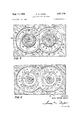
- FIGURE 5 illustrates the rear side of the end sealing plates of the gear pump taken along line 55 of FIG- URE 4 but reversed vertically so that the top of the plate in FIGURE 5 will correspond to the top of the plate as viewed in FIGURE 3 and FIGURE 6.
- FIGURE 6 illustrates the front side of the end sealing plates taken along line 6-6 of FIGURE 4.
- FIGURE 7 is an enlarged partial sectional view taken along line 7-7 of FIGURE 3.
- a hydrostatic coupling 10 for transmitting power from a first shaft, for example, driving shaft 11, to a second shaft, for example, shaft 12.
- the housing 13 is rigidly connected to the first shaft 11 and has rigidly formed therein a plurality of gear pump units 14.
- These pump units are comprised of main pump gears 15 and idler pump gears 16.
- these pump units pump fluid from the low pressure portion 17 of the housing to high pressure chamber 18 from which the fluid flows through passage 19 to valve 20.
- valve 20 When the valve 20 is open the fluid flows back to the low pressure portion 17 and when the valve is closed the pressure in chambers 18 and 19 builds up until the gears of the pump can practically no longer turn.
- An inner sun gear is rigidly connected to the shaft 12 and in driving engagement with the main gear 15 of each pump unit 14.
- valve 20 When the valve 20 is wide open the rotational movement of shaft 11 and housing 13, relative to gear 25, will cause pumping of liquid from 17 to 18. However the housing will merely continue to rotate about the sun gear 25 as the main pump gears 15 roll around gear 25 in planetary fashion. However, if valves 20 are closed, pressure will build up in chamber 18 until the pump gears practically can no longer turn. Rotation of the housing 13 will then cause simultaneous rotation of the sun gear through its engagement with non-turning main pump gears 15. The amount of torque transmitted from the outer housing to the sun gears 25 can to a large extent be varied and controlled by regulating the opening pressure provided by valve 20.
- FIGURES 3 through 7 illustrate the detailed arrangement of the gear pump and, in particular, the end plate construction according to the present invention.
- the two gears of the gear pump differ only in that one is in engagement with the sun gear 25 while the other is an idler gear. Otherwise, the structure, purpose and operation of the two gears and their associated end plates are identical. Therefore, the same numerals will be employed to designate like parts on the two separate gears except that the numerals associated with gear 15 will be in the 100 series and only the structure and operation of the elements associated with gear 15 will be discussed in detail.
- FIGURES 3 and 4 there is shown a gear shaft surrounded by a sleeve 31.
- Needle roller bearings 32 separate the sleeve 31 from an annular toothed pump gear 33.
- a substantially annular recess 34 is provided in the pump housing 14 adjacent the end of the toothed pump gear 33. This recess is formed by a fiat rear wall 35, an inner wall formed by a cylindrical hub 36 and a substantially cylin drical outer peripheral wall 38.
- the inner wall 36 of the recess is separated from an aperture 37 in the pump housing 14 through which the shaft 30 and sleeve 31 project.
- the recess 34 is separated from the portion which supports the shaft 30 and sleeve 31 of the gear.
- an end sealing plate 40 having an annular peripheral groove around the outer periphery thereof, which groove has an O-ring 42 mounted therein.
- This O-ring may be of a synthetic material such as Viton.
- a second groove 43 is formed in the rear of the plate 40 which groove has mounted therein a rear sealing ring 44 having a rearwardly extending lip 45. Ring 44 may also be of a synthetic material such as Viton.
- FIGURE 4 shows the two O-rings 42 and 142 contacting each other where the plates abut.
- a plate 47 is placed into the large recess formed by grooves 41 and 141.
- the end plate 40 floats in recess on rings 42 and 44 avoiding metal to metal contact with the recess except at a point or line contact on hub 36.
- the plate can tilt about its axis as one side of the plate moves out of the recess and ring 42 slides along surface 38 away from bottom surface and the other side of the plate moves into the recess and the other side of ring 42 moves into the recess.
- FIGURES 5 and 6 the details of the end plates are shown from the rear and from the front side respectively.
- the end plate having an inner perimeter 50 spaced from hub 36 and an outer perimeter 51 spaced from the outer peripheral wall 38 of the recess by the outwardly extending portion of O-ring 42.
- Raised portions 46 of the plate 40, together with the rearwardly extending lip 45 on O- ring 44 divides the rear of the plate into two portions, a high pressure pocket 52 behind the high pressure portion of the gear pump and a low pressure pocket 53 (which includes the entire central hub 36) behind the low pressure portion of the gear pump.
- Through holes 54 connect pocket 52 to the high pressure side of the pump while through holes 55 connect to the pocket 53 to the low pres sure side of the pump.
- Notches 59 are provided in the inner perimeter 50 of plate 40 for providing communication of low pressure fluid from the pocket 53 to the front surface of the end plate for reasons to be discussed in more detail below.
- FIGURE 5 also illustrates the preferred path of the sealing ring 44.
- the groove for this sealing ring at the pressure side follows the inner periphery 50 of the end plate 40 along an arc indicated by the angle a of approximately to 100.
- the sealing ring follows a curved path represented by angle ,8 for approximately to It is desirable to place the seal 44 as close to the edge 51 as possible to provide a large pressure pocket 53 having a large moment acting to prevent tilting of the plate by offsetting the tilting moment created by high pressure pocket 52.
- the grooves also follow the abutting edges 58 and 158. Those portions of the groove between the curved portions are straight line connections.
- the two rings 42 and 44 shall not lie in the same radial plane, and the plate must be thick enough to accommodate both grooves 41 and 43. See FIGURE 4. Aside from this factor, however, the plates should be as thin as possible to reduce the effects of centrifugal force urging the plates outwardly as much as possible.
- FIGURE 6 illustrates the front of the end plates and the flow of liquid thereto for purposes of lubrication.
- Circular grooves 70 are in communication with notches 59 by radial grooves 71 thereby passing low pressure lubricating fluid around the entire inner periphery 50 and also to extensions 72 of grooves 7 to provide lubricating oil on the low pressure side of the pump in pockets 73.
- high pressure pockets 74 are provided at the high pressure side of the pump.
- gear pump When the gear pump is employed as a compressor or pneumatic motor (expander) liquid will not be available to lubricate the contact surfaces between the end plates and the ends of the gears. In this instance these contact surfaces can be formed with an anti-friction material.
- trap pocket release ports 75 provided at the high pressure side of the pump. These trap pocket release ports are larger than trap pocket release ports normally employed. The reason for this is that since under some conditions the speed of the gears will be very high it will also be necessary to allow an increased volume of fluid to escape from the trap pockets between the meshing gear teeth with limited pressure drop. The pressure in the trap pocket increases with the square of the speed and therefore these large pocket release ports will decrease the resistance to oil moving out of the meshing gear teeth. It must be kept in mind that at times these gears will rotate at speeds greater than normal pump speeds. If the trap pocket release ports are not suflicient, pressure chokes strong enough to destroy the bearings will occur. Trap port 76 is also provided on the low pressure side of the plate.
- a pump or motor comprising a casing, a low pressure chamber and a high pressure chamber, a pair of rotary intermeshing gears mounted in the casing for carrying fluid from one of said pressure chambers to the other pressure chamber, at least one pair of end plates mounted in said casing at least one end of said pair of gears, and in sealing engagement with the ends of the gears, means for mounting said end plates in said casing for universal movement whereby the said end plates are capable of maintaining their axes perpendicular to the said ends of its meshing gears as the position of the axes of the said gears change with respect to the casing.
- a pump or motor as claimed in claim 1 including a means for exerting a pressure force on the end plates urging them against the said ends of the said gears.
- a pump or motor as claimed in claim 2 including a pair of substantially annular recesses-in said casing adjacent the said ends of the said gears, said end plates being substantially annular and being mounted one within each said recess, each said recess having a substantially annular bottom surface, a substantially cylindrical outer surface and a substantially cylindrical inner surface, resilient means for spacing each said end plate from the said bottom surface and from the said outer surface of its recess, and the inner circumference of each said end plate being of a larger diameter than the inner surface of its recess, whereby each said end plate floats on said resilient means within its recess whereby said universal movement is obtained.
- a pump or motor as claimed in claim 4 wherein said second resilient ring divides the rear side of the end plate into a high pressure pocket and a low pressure pocket, said high pressure pocket being located across the end plate from the high pressure chamber of the pump, and the said low pressure pocket being located across the end plate from the low pressure chamber of the pump.
- a pump or motor as claimed in claim 5 wherein the said low pressure pocket comprises the area between the end plate and the bottom of the recess bounded by the second resilient ring and the said high pressure pocket lies outside of the area bounded by the second resilient ring, said second resilient ring having a portion extending for more than adjacent to the outer circumference of the end plate across from the low pressure chamber.
- a pump or motor as claimed in claim 8 including a means for directing fluid from the low pressure pocket to the front side of the end plate facing the gear to lubricate the said front side.
- a pump or motor as claimed in claim 5 in which the size of the high pressure pocket between the end plates and the bottom of the recess is bounded by the second resilient ring and said secondary resilient ring has a portion extending approximately for adjacent to the outer circumference of the end plate across from the low pressure chamber.
- each of the said rings is located within separate grooves in the end plate and the thickness of the end plate is slightly greater than the sum of the axial dimensions of the two grooves.
- a pump or motor as claimed in claim 4 wherein the said end plates mounted at the same end of the pump or motor abut in the plane midway between the axes of the two gears and including a guard plate member for sealing the pump or motor chambers where the two plates abut.
- a pump or motor as claimed in claim 3 including a means for preventing rotational movement of said end plates, said means including a pin extending from the bottom of each recess into an aperture in the side of the plates facing the bottom of its recess.
- a pump or motor as claimed in claim 3 including a trap pocket release port on the side of the end plates facing the gears and extending circumferentially for more than 45.
- a hydrostatic coupling device of the gear pump type for transmitting power from a first shaft to a second shaft, wherein one shaft has rigidly connected thereto a plurality of gear pump units planetarily mounted about and engaged with a sun gear connected to the other shaft; wherein said gear pump units comprise a casing, a low pressure chamber and a high pressure chamber, a pair of rotary intermeshing gears mounted in the casing for carrying fluid from the low pressure chamber to the high pressure chamber, at least one pair of end plates mounted in said casing at least one end of said pair of gears, and in sealing engagement with the ends of the gears, means for mounting said end plates in said casing for universal movement whereby the said end plates are capable of maintaining their axes perpendicular to the said ends of the gears as the position of the axes of the said gears change with respect to the casing when subjected to centrifugal forces created when the said one shaft of the hydrostatic coupling rotates about its axis.
- a hydrostatic coupling device as claimed in claim 16 including a means for exerting a pressure force on the end plates urging them against the said ends of the said gears.
- a hydrostatic coupling device as claimed in claim 16 including a pair of substantially annular recesses in said casing adjacent the said ends of the said gears, said end plates being substantially annular and being mounted one within each said recess, each said recess having a substantially annular bottom surface, a substantially cylindrical outer surface and a substantially cylindrical inner surface, resilient means for spacing each said end .plate from the said bottom surface and from the said outer surface of its recess, and the inner circumference 9 10 of each said end plate being of a larger diameter than References Cited the inner surface of its recess, whereby the said resilient means allows each said end plate to float within its recess UNITED STATES PATENTS whereby said universal movement is obtained.
- a hydrostatic coupling device as claimed in claim 5 3,068,804 12/ 196 2 Thrap et a1 103-126 16 including a trap pocket release port on the side of the 3,213,982 10/1965 Ahlen 19261 XR end plates facing the gears and extending circumferentially for more than 45.
Landscapes
- Engineering & Computer Science (AREA)
- General Engineering & Computer Science (AREA)
- Mechanical Engineering (AREA)
- Rotary Pumps (AREA)
Applications Claiming Priority (1)
| Application Number | Priority Date | Filing Date | Title |
|---|---|---|---|
| GB28876/66A GB1195365A (en) | 1966-06-28 | 1966-06-28 | Improvements in and relating to Hydraulic and Pneumatic Gear Pumps or Motors |
Publications (1)
| Publication Number | Publication Date |
|---|---|
| US3401778A true US3401778A (en) | 1968-09-17 |
Family
ID=10282589
Family Applications (1)
| Application Number | Title | Priority Date | Filing Date |
|---|---|---|---|
| US597631A Expired - Lifetime US3401778A (en) | 1966-06-28 | 1966-11-29 | Gear type pump or motor |
Country Status (4)
| Country | Link |
|---|---|
| US (1) | US3401778A (cs) |
| CS (1) | CS189651B2 (cs) |
| DE (1) | DE1653898A1 (cs) |
| GB (1) | GB1195365A (cs) |
Cited By (2)
| Publication number | Priority date | Publication date | Assignee | Title |
|---|---|---|---|---|
| US3918857A (en) * | 1972-11-10 | 1975-11-11 | William Maurice Bar Fitzgerald | Hydraulic motors with intermeshing sun and planet gears |
| US3965012A (en) * | 1973-12-11 | 1976-06-22 | Kanegafuchi Kagaku Kogyo Kabushiki Kaisha | Membrane separation apparatus |
Families Citing this family (1)
| Publication number | Priority date | Publication date | Assignee | Title |
|---|---|---|---|---|
| CH649133A5 (de) * | 1980-10-29 | 1985-04-30 | Glyco Antriebstechnik Gmbh | Zahnradpumpenanordnung. |
Citations (3)
| Publication number | Priority date | Publication date | Assignee | Title |
|---|---|---|---|---|
| US2931472A (en) * | 1957-08-16 | 1960-04-05 | Svenska Rotor Maskiner Ab | Hydraulic transmission |
| US3068804A (en) * | 1960-03-21 | 1962-12-18 | Thompson Ramo Wooldridge Inc | Pressure loaded pump seal |
| US3213982A (en) * | 1959-12-19 | 1965-10-26 | Svenska Rotor Maskiner Ab | Transmission comprising a hydrostatic coupling and a hydrodynamic torque converter in series |
-
1966
- 1966-06-28 GB GB28876/66A patent/GB1195365A/en not_active Expired
- 1966-11-29 US US597631A patent/US3401778A/en not_active Expired - Lifetime
-
1967
- 1967-06-20 DE DE19671653898 patent/DE1653898A1/de active Pending
- 1967-06-21 CS CS674546A patent/CS189651B2/cs unknown
Patent Citations (3)
| Publication number | Priority date | Publication date | Assignee | Title |
|---|---|---|---|---|
| US2931472A (en) * | 1957-08-16 | 1960-04-05 | Svenska Rotor Maskiner Ab | Hydraulic transmission |
| US3213982A (en) * | 1959-12-19 | 1965-10-26 | Svenska Rotor Maskiner Ab | Transmission comprising a hydrostatic coupling and a hydrodynamic torque converter in series |
| US3068804A (en) * | 1960-03-21 | 1962-12-18 | Thompson Ramo Wooldridge Inc | Pressure loaded pump seal |
Cited By (2)
| Publication number | Priority date | Publication date | Assignee | Title |
|---|---|---|---|---|
| US3918857A (en) * | 1972-11-10 | 1975-11-11 | William Maurice Bar Fitzgerald | Hydraulic motors with intermeshing sun and planet gears |
| US3965012A (en) * | 1973-12-11 | 1976-06-22 | Kanegafuchi Kagaku Kogyo Kabushiki Kaisha | Membrane separation apparatus |
Also Published As
| Publication number | Publication date |
|---|---|
| GB1195365A (en) | 1970-06-17 |
| DE1653898A1 (de) | 1970-09-17 |
| CS189651B2 (en) | 1979-04-30 |
Similar Documents
| Publication | Publication Date | Title |
|---|---|---|
| US3472170A (en) | High pressure gear pump or motor with compensation for play and wear | |
| US4265602A (en) | Gear pump with low pressure shaft lubrication | |
| US3852003A (en) | Pressure-sealed compressor | |
| US3833317A (en) | Rotary gear motor/pump having hydrostatic bearing means | |
| US3932073A (en) | Screw rotor machine with spring and fluid biased balancing pistons | |
| US2956512A (en) | Hydraulic pump or motor | |
| US3007418A (en) | Variable delivery hydraulic pump or motor | |
| US1990750A (en) | Variable volume pump and hydraulic transmission | |
| US3221665A (en) | Hydraulic pump or motor with hydraulic pressure-responsive vane | |
| US2915982A (en) | Rotary pump | |
| US3711227A (en) | Vane-type fluid pump | |
| US2880677A (en) | Variable volume vane pump | |
| US3401778A (en) | Gear type pump or motor | |
| US4337018A (en) | Rotary impeller pump or motor with counterbalancing chamber in thrust plate bearing counterbore | |
| US1749058A (en) | Rotary pump | |
| US3969986A (en) | Radial piston pump | |
| US2952215A (en) | Variable delivery high speed and pressure vane pump | |
| US3724975A (en) | Gear motor or pump | |
| US5485725A (en) | Continuously variable transmission | |
| EP1880109B1 (en) | Rotor sliding-vane machine | |
| US3854849A (en) | Distribution of valve-gear systems for rotary machines | |
| US2096074A (en) | Rotary compressor-motor apparatus | |
| US3930766A (en) | Radial balancing means for a hydraulic device | |
| US2993339A (en) | Rotary, hydraulic pump and motor transmission | |
| US4292013A (en) | Rotary impeller or motor with pressure balanced end plates |