US3373982A - Radial grate for shaft kilns - Google Patents
Radial grate for shaft kilns Download PDFInfo
- Publication number
- US3373982A US3373982A US498891A US49889165A US3373982A US 3373982 A US3373982 A US 3373982A US 498891 A US498891 A US 498891A US 49889165 A US49889165 A US 49889165A US 3373982 A US3373982 A US 3373982A
- Authority
- US
- United States
- Prior art keywords
- grate
- openings
- kiln
- opening
- plates
- Prior art date
- Legal status (The legal status is an assumption and is not a legal conclusion. Google has not performed a legal analysis and makes no representation as to the accuracy of the status listed.)
- Expired - Lifetime
Links
- 239000000463 material Substances 0.000 description 24
- 239000007787 solid Substances 0.000 description 14
- 239000012530 fluid Substances 0.000 description 13
- 230000007246 mechanism Effects 0.000 description 3
- 230000008859 change Effects 0.000 description 2
- 238000007599 discharging Methods 0.000 description 2
- 230000004048 modification Effects 0.000 description 2
- 238000012986 modification Methods 0.000 description 2
- 235000008733 Citrus aurantifolia Nutrition 0.000 description 1
- 238000006219 Matteson homologation reaction Methods 0.000 description 1
- 235000011941 Tilia x europaea Nutrition 0.000 description 1
- 238000001354 calcination Methods 0.000 description 1
- 239000003245 coal Substances 0.000 description 1
- 238000004939 coking Methods 0.000 description 1
- 238000002485 combustion reaction Methods 0.000 description 1
- 238000012937 correction Methods 0.000 description 1
- 230000003247 decreasing effect Effects 0.000 description 1
- 238000013461 design Methods 0.000 description 1
- 229910000514 dolomite Inorganic materials 0.000 description 1
- 239000010459 dolomite Substances 0.000 description 1
- 230000005484 gravity Effects 0.000 description 1
- 239000004571 lime Substances 0.000 description 1
- ZLNQQNXFFQJAID-UHFFFAOYSA-L magnesium carbonate Chemical compound [Mg+2].[O-]C([O-])=O ZLNQQNXFFQJAID-UHFFFAOYSA-L 0.000 description 1
- 229910000021 magnesium carbonate Inorganic materials 0.000 description 1
- 235000014380 magnesium carbonate Nutrition 0.000 description 1
- 239000001095 magnesium carbonate Substances 0.000 description 1
- 238000000034 method Methods 0.000 description 1
- 230000010355 oscillation Effects 0.000 description 1
- 230000008569 process Effects 0.000 description 1
- 230000009467 reduction Effects 0.000 description 1
- 230000000284 resting effect Effects 0.000 description 1
- 239000011343 solid material Substances 0.000 description 1
Images
Classifications
-
- F—MECHANICAL ENGINEERING; LIGHTING; HEATING; WEAPONS; BLASTING
- F27—FURNACES; KILNS; OVENS; RETORTS
- F27B—FURNACES, KILNS, OVENS OR RETORTS IN GENERAL; OPEN SINTERING OR LIKE APPARATUS
- F27B1/00—Shaft or like vertical or substantially vertical furnaces
- F27B1/08—Shaft or like vertical or substantially vertical furnaces heated otherwise than by solid fuel mixed with charge
-
- F—MECHANICAL ENGINEERING; LIGHTING; HEATING; WEAPONS; BLASTING
- F27—FURNACES; KILNS; OVENS; RETORTS
- F27B—FURNACES, KILNS, OVENS OR RETORTS IN GENERAL; OPEN SINTERING OR LIKE APPARATUS
- F27B1/00—Shaft or like vertical or substantially vertical furnaces
- F27B1/10—Details, accessories or equipment specially adapted for furnaces of these types
- F27B1/21—Arrangements of devices for discharging
Definitions
- ABSTRACT OF THE DISCLOSURE A discharge mechanism for shaft furnaces having narrow, concentric radial openings extending outwardly from the furnace center, with a retarder plate mounted under each opening, to prevent direct vertical movement of material, and an oscillating pusher bar is mounted on each retarder plate in close proximity to the edges of the openings pushes material from both sides of the plate, discharging it from the furnace.
- Each opening has radially directed side edges so that oscillation of the pusher bar pushes material uniformly from each plate, providing uniform flow of material across the lateral extent of the furnace.
- This invention relates to improvements in shaft kilns and particularly to the discharge grate for such units.
- a process equipment which is an upright vessel commonly called -for burning or calcining lime, coking coal, burning mag nesite, dolomite, etc-
- the equipment commonly includes a circular cross-section, vertical vessel having means for uniformly feeding granular or pulverulent material across its lateral extent, a lower discharge means for uniformly discharging material across the lateral extent of the kiln, and means for introducing at least one stream of treating gas or fluid into some portion of the pulverulent material.
- the cross-sectional dimensions of such equipment increase, considerable problems occur in attempting to uniformly discharge material from the contained mass so as to provide uniform movement through the kiln and a uniform treatment of all of the material as it passes through the kiln.
- an object of the invention to provide apparatus for uniformly removing solids from the lower portion of shaft vessels so as to provide a uniform movement of the solids across the lateral extent of such kilns.
- Another object of the invention is to'provide discharge apparatus for shaft kilns which is arranged to distribute treatment fluids uniformly throughout the lateral extent of the 16TH for passage through the contained material.
- Another object of the invention is to provide a kilncontained discharge grate and operating mechanism for shaft kilns.
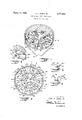
- FIG. 1 is a diagrammatic, perspective view of a grate for a shaft kiln according to the invention
- FIG. 2 is a top plan view of the grate of FIG. 1
- FIG. 3 is an enlarged detail, in cross-section, of one form of a discharge grate according to the invention
- FIG. 4 is a detailed cross-sectional view of a modified form of the grate according to the invention.
- FIG. 5 is a partial perspective view of a grate, according to the invention, showing the reduction in height of the 3,373,982 Patented Mar. 19, 1968 pusher bar from the central section to the concentric section.
- the grate of the invention provides a means for supporting a load of pulverulent material in a vertical vessel of a circular cross-section, such as a shaft kiln, and the grate provides means for discharging material from the load at a predetermined rate.
- the grate provides a central circular portion with discharge openings, and at least one annular portion around the central portion with discharge openings. The total area of the openings in the annular portion is substantially more than the central portion. When the radial dimension of both portions is about equal, approximately twice the area of openings is needed for the annular area to provide uniform discharge of the material.
- the design of the grate is arranged as a volumertic discharge mechanism, and pushers control the flow of solids through the grate so as to provide a uniform movement of the contained solids across the lateral extent of the kiln.
- the uniform rate of flow of solids across the lateral ex- .tent of the kiln is determined by the positioning and geometry of the openings in the kiln as well as the movement and positioning of the pushers which extend radially outwardly from the central point in the kiln.
- a vertical circular wall 10 is constructed of material necessary to contain the material under treatment. In the case of a kiln the material is refractory or the like.
- a conical bottom 12 is provided closing the lower end of the vessel with a central outlet 14 at the cone apex.
- the height of the vessel (above the grate) is determined by the treatment desired and is well known in the art. Additionally, feed apparatus for the device is well known in the art.
- the lower outlet 14 may be closed and fluid may be passed into the cone below the grate so that it passes through the carried load.
- a grate shown in general by numeral 16, is mounted in the lower part of the kiln 10, and it is composed of a set of spaced apart plates having staggered openings to prevent direct gravity discharge along vertical lines.
- the grate structure may be mounted on support beams 18 and 20, shown in dashed lines in FIG. 2 for clarity, which pass through the conical member 12.
- the beams may, therefore, support the weight of the grate as well as the carried load on the grate.
- the use of I-beams and the like is well known for such purposes and does not form a part of this invention.
- the grate includes an upper deflecting plate member and a lower retaining plate member, with pushers mounted on the lower retaining plate member for pushing material therefrom into the conical base 12.
- the central circular portion of the deflector member shown in FIG. 2, includes a series of triangular shaped openings, member 30 indicating one opening, leaving a deflector portion 22 connected to an outwardly extending portion 23 in the outer annular portion, and another similar outwardly extending portion 24 spaced therefrom providing an opening 25 therebetween.
- the adjacent section of the deflector includes a deflector portion 26 in the central portion connected to two spaced apart outer portions 27 and 28 leaving an opening 29 therebetween.
- a triangular shaped opening 30 with its edge in essentially one plane as shown in FIG. 2 is left between the two deflector portions 22 and 26, and an opening 32 remains between deflectors 24 and 27.
- a retainer plate 35 which is circular and has a series of cut-out portions, explained below, is mounted below the deflector plate.
- the retainer plate is arranged to provide a portion under each opening in the deflector with the edges thereof under the deflector to prevent a direct vertical passage through the grate.
- An aperture or opening in the retainer plate is provided under each one of the deflector plates mounted thereabove.
- elongated shaped section 35 extends from the center of the kiln to about the wall. Wedge-shaped openings are provided below the deflector portions above the retainer plate. Thus, there is an opening below deflector portions and a retainer plate portion below the openings in the deflector plate.
- a series of radial pushers are pivotally attached about a central pivot fastening means (not shown) centrally of the kiln.
- radial pushers 38 extend from the kiln wall to the pivot point at the kiln center
- short pushers 39 extend from about the kiln wall to an intermediate retainer ring 40 between the central section and the annular section.
- These are alternately spaced around the kiln grate so that a pusher bar is positioned in each of the openings in the diverter plate for discharge of material on movement.
- the outer ends of the pushers are mounted on an outer ring 41 in addition to the ring 40 to provide stability of the pushers.
- the pushers may be actuated by means of a hydraulic cylinder 42, or other actuating mechanism for pivoting the same around the central pivot point.
- the hydraulic lines for fluid or electric leads for electric motors, etc. are not shown for drawing clarity.
- An hydraulic cylinder is an effective actuator since it may be attached between two pushers (with a lost motion connection to permit minor alignment correction).
- the actuation of the cylinders oscillate the pushers in a radial pivoting movement across the opening under which they are residing.
- the actuator 42 is provided with a piston rod 43 attached to a short pusher 39 and the opposed piston rod 44 is attached to next adjacent long pusher bar 38. As shown in FIG.
- the retainer plates are mounted below the divider plates, a sufficient distance to permit the pushers to pass therebetween, and usually suflicient to prevent the larger lumps of the pulverulent material from bridging across the openings therebetween.
- FIG. 3 shows the positioning of the divider plates and the retainer plates mounted therebelow.
- the divider plates 23a and 24a are flat plates and are mounted spaced apart with a retainer plate 36a mounted therebelow.
- the pusher bar 39 is resting on the retainer plate 36 actuated by the push rod 43 from an actuator for moving solid material from the plate.
- diverter plates 50 and 51 are angles rather than flat plates as illustrated above, and these plates are juxtaposed above a retainer pl-ate 36a.
- a pusher bar 53 is mounted on rollers 54 on the plate 36a and a push rod 43a actuated 'by an actuator oscillates the pusher back and forth on the plate below the diverter plates 50 and 51.
- a seal may be placed over the bottom opening 14 and the fluids injected into the conical bottom 12.
- conduits or the like may be extended through the wall of a kiln beneath the diverter plates whether they are flat or angular and either by providing holes through the diverter plates or letting the fluids pass around the edges of the plates, the fluids may be injected into the bed of solids.
- both may be fed into the top of the vessel and the fluids either removed above or below the grate with shed-type collectors for separating the fluid from the solids.
- the treatment is a burning or flame treatment of a solid it may be desirable to bring one of the gaseous components for combustion through the grate and into the moving mass. Other portions of the gaseous component may be injected into the moving bed above the grate depending on the treatment.
- a single, circular configuration of openings in the grate may be satisfactory.
- the diameter of the vessel increases, it may be necessary to increase the number of circular opening components.
- two sets of openings are provided in the grate, i.e., an inner set and an Outer set.
- the vessel diameter increases still further it may be necessary to add still other sets of openings in annular configuration generally concentrically.
- the height of the pushers on the outer series normally is reduced, since the number of openings is normally increased.
- a pusher bar has an inner section 38a and a reduced height outer section 38b.
- the pusher bar is mounted on an inner support ring 40a and an outer support ring 41a. As additional sections are needed due to an increase in diameter of kiln, the pusher bar for each section is further reduced in height.
- the decrease in height of the pushers should be proportional to the change in the number of pushers and the area of the openings so as to maintain a uniform flow of solids through the kiln and particularly to maintain a uniform flow of material through a cross-section of the kiln.
- the formula for determining the height of the pusher bar for each section is:
- H is the height of the pushers at each section N is the number of pushers in the section K is the volumetric efliciency factor C is a constant.
- the height of the pusher 38b is approximately /2 of the height of pusher 38a since there are twice as many pushers in the outer section as in the inner section. K and C are determined for each kiln.
- Grate means for a vertical, circular vessel having an upstanding wall comprising radially directed diverter means mounted adjacent the lower end of said vessel, said diverter means providing at least two portions across the lateral extent of said vessel, one portion being a central circular area and at least one annular portion contiguous and concentric with said central portion, there being a first series of spaced apart, radially directed openings in said diverter means in said central portion from adjacent the center to the edge thereof and there being a second series of spaced-apart radially directed openings in said concentric portion, each said opening having an edge therearound in substantially one plane, and the total area of the openings in said at least one concentric portion being substantially greater than the total area of the openings in said central portion; retarder plate means inclusive of radially directed side edges mounted below and spaced from each said opening With said radially directed edges extending underneath the edges of said radially directed openings to prevent direct vertical passage of material therethrough; pusher bar means mounted on a central pivot and extending radially outwardly mounted on said
- Grate means according to claim 1 wherein said means for oscillating said pusher bars are hydraulic cylinders mounted below said diverter means at spaced intervals arounds the extent of said annular portion.
- Grate means according to claim 1 wherein said retarder plate means is a circular, generally fiat member with openings therein spaced below said retarder means.
- Grate means according to claim 1 wherein the height of the pusher bar is decreased in each portion extending outwardly from the center thereof.
- Grate means for a vertical, circular vessel having an upstanding outer wall comprising radially directed diverter means mounted adjacent the lower end of said vessel, said diverter means providing at least one portion across the lateral extent of the vessel and being a circular area including a series of spaced-apart radially directed openings from adjacent the center to the edge thereof, each said opening having an edge therearound in substantially one plane and each inclusive of a pair of radially directed side edges; retarder plate means inclusive of radially directed side edges mounted below and spaced from each said opening with said radially directed edges extending underneath the edges of the radially directed openings to prevent direct vertical passage of material therethrough; pusher bar means mounted on a central pivot and extending radially outwardly mounted on said retarder plate means and arranged with one pusher bar below each said opening, each said pusher bar being a narrow bar substantially less in Width than the opening with which it is associated, each said pusher bar being mounted in close proximity to said edge in one plane around each said opening, said pusher bar means including means s
Landscapes
- Engineering & Computer Science (AREA)
- Mechanical Engineering (AREA)
- General Engineering & Computer Science (AREA)
- Furnace Details (AREA)
Priority Applications (2)
| Application Number | Priority Date | Filing Date | Title |
|---|---|---|---|
| US498891A US3373982A (en) | 1965-10-20 | 1965-10-20 | Radial grate for shaft kilns |
| BE720843D BE720843A (en, 2012) | 1965-10-20 | 1968-09-13 |
Applications Claiming Priority (1)
| Application Number | Priority Date | Filing Date | Title |
|---|---|---|---|
| US498891A US3373982A (en) | 1965-10-20 | 1965-10-20 | Radial grate for shaft kilns |
Publications (1)
| Publication Number | Publication Date |
|---|---|
| US3373982A true US3373982A (en) | 1968-03-19 |
Family
ID=23982930
Family Applications (1)
| Application Number | Title | Priority Date | Filing Date |
|---|---|---|---|
| US498891A Expired - Lifetime US3373982A (en) | 1965-10-20 | 1965-10-20 | Radial grate for shaft kilns |
Country Status (2)
| Country | Link |
|---|---|
| US (1) | US3373982A (en, 2012) |
| BE (1) | BE720843A (en, 2012) |
Cited By (4)
| Publication number | Priority date | Publication date | Assignee | Title |
|---|---|---|---|---|
| US3704011A (en) * | 1971-08-12 | 1972-11-28 | Mintech Corp | Discharge mechanism for shaft kiln |
| US3777940A (en) * | 1971-11-10 | 1973-12-11 | Paraho Corp | Bottom fluid distributor for shaft vessels |
| US5366170A (en) * | 1993-09-17 | 1994-11-22 | John B. Jones, Jr. | Vertical shaft processor including an improved removal grate |
| US20120003066A1 (en) * | 2010-06-30 | 2012-01-05 | Ctb, Inc. | Circular bin unload system and method |
Citations (4)
| Publication number | Priority date | Publication date | Assignee | Title |
|---|---|---|---|---|
| US2148946A (en) * | 1935-12-04 | 1939-02-28 | American Lurgi Corp | Device for discharging materials |
| US3027147A (en) * | 1959-05-06 | 1962-03-27 | Cameron And Jones Inc | Circular shaft kiln discharge grate |
| US3064960A (en) * | 1961-04-26 | 1962-11-20 | Beckenbach Karl | Apparatus for removing burnt or calcined material from furnaces |
| US3202405A (en) * | 1962-07-18 | 1965-08-24 | Midland Lime Inc | Vertical shaft kiln and method of operation thereof |
-
1965
- 1965-10-20 US US498891A patent/US3373982A/en not_active Expired - Lifetime
-
1968
- 1968-09-13 BE BE720843D patent/BE720843A/xx unknown
Patent Citations (4)
| Publication number | Priority date | Publication date | Assignee | Title |
|---|---|---|---|---|
| US2148946A (en) * | 1935-12-04 | 1939-02-28 | American Lurgi Corp | Device for discharging materials |
| US3027147A (en) * | 1959-05-06 | 1962-03-27 | Cameron And Jones Inc | Circular shaft kiln discharge grate |
| US3064960A (en) * | 1961-04-26 | 1962-11-20 | Beckenbach Karl | Apparatus for removing burnt or calcined material from furnaces |
| US3202405A (en) * | 1962-07-18 | 1965-08-24 | Midland Lime Inc | Vertical shaft kiln and method of operation thereof |
Cited By (5)
| Publication number | Priority date | Publication date | Assignee | Title |
|---|---|---|---|---|
| US3704011A (en) * | 1971-08-12 | 1972-11-28 | Mintech Corp | Discharge mechanism for shaft kiln |
| US3777940A (en) * | 1971-11-10 | 1973-12-11 | Paraho Corp | Bottom fluid distributor for shaft vessels |
| US5366170A (en) * | 1993-09-17 | 1994-11-22 | John B. Jones, Jr. | Vertical shaft processor including an improved removal grate |
| US20120003066A1 (en) * | 2010-06-30 | 2012-01-05 | Ctb, Inc. | Circular bin unload system and method |
| US8668424B2 (en) * | 2010-06-30 | 2014-03-11 | Ctb, Inc. | Circular bin unload system and method |
Also Published As
| Publication number | Publication date |
|---|---|
| BE720843A (en, 2012) | 1969-02-17 |
Similar Documents
| Publication | Publication Date | Title |
|---|---|---|
| US2668041A (en) | Heat treatment of finely divided solids | |
| US2715565A (en) | Reactor furnaces | |
| US3854637A (en) | Apparatus for loading solid particles into a vertical vessel | |
| US5210962A (en) | Vertical shaft processor | |
| US3373982A (en) | Radial grate for shaft kilns | |
| EP1242639B1 (en) | Equipment for the even feed of pulverous material to a concentrate burner of suspension smelting furnace | |
| US3106385A (en) | Method and apparatus for solids blending | |
| US3401922A (en) | Linear grate for shaft kilns | |
| US4399846A (en) | Mechanism for granulometric distribution of solid particles | |
| US3092473A (en) | Cooler for sinter and the like | |
| US3415504A (en) | Material distributing device in a vertical kiln | |
| US3432348A (en) | Fluid distributor for vertical vessels | |
| US3721017A (en) | Apparatus for cooling particles | |
| US2812592A (en) | Heat treatment of finely-divided solids | |
| US3561927A (en) | Fluid collection system for vertical process vessels | |
| US3463617A (en) | Supporting plate for fluidized bed apparatus | |
| US640715A (en) | Vertical automatic drying and roasting furnace | |
| US3544089A (en) | Pneumatic elevators for lifting granular solids | |
| US3594287A (en) | Apparatus for cooling solids by direct contact with liquids | |
| US3360249A (en) | Discharge grate and hopper for shaft kiln | |
| US2553464A (en) | Heat recovery device | |
| US2520384A (en) | Furnace | |
| US20110132242A1 (en) | furnace chute | |
| US3034222A (en) | Fluidizing device | |
| US3777940A (en) | Bottom fluid distributor for shaft vessels |
Legal Events
| Date | Code | Title | Description |
|---|---|---|---|
| AS | Assignment |
Owner name: HOLME ROBERTS AND OWEN, 1700 BROADWAY, SUITE 1800 Free format text: SECURITY INTEREST;ASSIGNOR:PARAHO DEVELOPMENT CORPORATION;REEL/FRAME:004160/0879 Effective date: 19830726 Owner name: HOLME ROBERTS AND OWEN, A GENERAL PARTNERSHIP,COLO Free format text: SECURITY INTEREST;ASSIGNOR:PARAHO DEVELOPMENT CORPORATION;REEL/FRAME:004160/0879 Effective date: 19830726 |
|
| AS | Assignment |
Owner name: NEW PARAHO CORPORATION, THE Free format text: ASSIGNOR HEREBY RELEASES SECURITY INTEREST IN SAID PATENTS RECORDED ON REEL 4160 FRAME 879.;ASSIGNOR:HOLME ROBERTS & OWEN;REEL/FRAME:004613/0388 Effective date: 19860811 |