US3363243A - Electronic swim timer controlled by touch pad in swim lane - Google Patents
Electronic swim timer controlled by touch pad in swim lane Download PDFInfo
- Publication number
- US3363243A US3363243A US425793A US42579365A US3363243A US 3363243 A US3363243 A US 3363243A US 425793 A US425793 A US 425793A US 42579365 A US42579365 A US 42579365A US 3363243 A US3363243 A US 3363243A
- Authority
- US
- United States
- Prior art keywords
- lane
- swim
- oscillator
- timer
- touch pad
- Prior art date
- Legal status (The legal status is an assumption and is not a legal conclusion. Google has not performed a legal analysis and makes no representation as to the accuracy of the status listed.)
- Expired - Lifetime
Links
- 230000009182 swimming Effects 0.000 claims description 27
- 238000009527 percussion Methods 0.000 description 10
- XLYOFNOQVPJJNP-UHFFFAOYSA-N water Substances O XLYOFNOQVPJJNP-UHFFFAOYSA-N 0.000 description 5
- 239000012530 fluid Substances 0.000 description 3
- 230000001174 ascending effect Effects 0.000 description 2
- 238000010586 diagram Methods 0.000 description 2
- 230000002706 hydrostatic effect Effects 0.000 description 2
- 239000002184 metal Substances 0.000 description 2
- 238000000034 method Methods 0.000 description 2
- 239000000203 mixture Substances 0.000 description 2
- 230000035484 reaction time Effects 0.000 description 2
- 239000007858 starting material Substances 0.000 description 2
- 229910000831 Steel Inorganic materials 0.000 description 1
- 239000013078 crystal Substances 0.000 description 1
- 230000001934 delay Effects 0.000 description 1
- 230000003111 delayed effect Effects 0.000 description 1
- 239000011521 glass Substances 0.000 description 1
- 238000007654 immersion Methods 0.000 description 1
- 239000011810 insulating material Substances 0.000 description 1
- 239000007788 liquid Substances 0.000 description 1
- 229920001296 polysiloxane Polymers 0.000 description 1
- 230000005236 sound signal Effects 0.000 description 1
- 229910001220 stainless steel Inorganic materials 0.000 description 1
- 239000010935 stainless steel Substances 0.000 description 1
- 239000010959 steel Substances 0.000 description 1
- 230000000007 visual effect Effects 0.000 description 1
Images
Classifications
-
- H—ELECTRICITY
- H01—ELECTRIC ELEMENTS
- H01H—ELECTRIC SWITCHES; RELAYS; SELECTORS; EMERGENCY PROTECTIVE DEVICES
- H01H3/00—Mechanisms for operating contacts
- H01H3/02—Operating parts, i.e. for operating driving mechanism by a mechanical force external to the switch
- H01H3/14—Operating parts, i.e. for operating driving mechanism by a mechanical force external to the switch adapted for operation by a part of the human body other than the hand, e.g. by foot
- H01H3/141—Cushion or mat switches
Definitions
- Known timing apparatus for swimming races has the disadvantage that, even though the apparatus itself may be accurate, it must be started and stopped manually and errors occur due to variations in the reaction times of the judges of the race.
- the judges may have to wait for a photograph of the finish to be developed before the result can be determined and announced. Also it is difficult for the judges to determine whether or not a swimmer leaves the start position before the starting signal is given both at the beginning of races and during changeovers in relay races.
- a further disadvantage of known starting and timing methods is that the competitors, when on their starting blocks, are not at equal distances from the instrument which gives the audible start signal, and thus, due to the low speed of sound, receive the start signal after different intervals. With a pool width of 35 yards the difference in the time between the sound signal reaching two competitors in a swimming race could be as much as one tenth of a second.
- the invention has among its objects to mitigate these disadvantages and to provide automatic timing means for timing races.
- automatic timing apparatus for races comprises an oscillator, a timer for each competitor in the race, means for connecting each of the timers to the oscillator when a start signal is given, and means for disconnecting each timer from the oscillator upon the corresponding competitor reaching the finishing position of the race.
- the automatic timing apparatus may be provided for timing races in swimming pools and may comprise switch means effective to connect electrically operated means to a power source, the electrically operated means being effective to operate percussion apparatus provided in or near each of a plurality of starting blocks, a starting block being provided in each lane of the swimming pool, the percussion apparatus providing an individual audible start signal to each competitor in the race, the switch means being also effective to connect timers to an oscillator, which oscillator is adapted to supply high frequency pulses to operate the timers until disconnected therefrom by further switch means operated by the competitors and provided at the finishing position in each lane of the swimming pool.
- the further switch means may comprise a pair of contacts provided in waterproof pads which pads are provided at each end of each swimming lane of a swimming pool, so that closure of the further switch means is effective to disconnect the associated timer from the oscillator and to cause the timer to transmit a signal to serializer means, the serializer means being effective to process the signals from the timers and to arrange them in ascending order of the duration of connection of each of the timers with the oscillator.
- Automatic or manually operated means may be pro- 3,363,243 Patented Jan. 9, 1968 vided for indicating the sequence in which the competitors have completed the race and the time that each competitor has taken.
- the automatic timing means may include false start means provided at the position at which each competitor starts the race, which false start means are effective to indicate whether or not the competitor leaves the start position before the start signal is given.
- the false start means may include a .pad containing a pair of contacts, the pad being positioned in the top surface of the block on which the swimmer stands, and from which block he dives at the start of the race.
- the false start means may include a hinged platform provided on the starting block on which the swimmer stands and from which he dives to start a race, the hinged platform being used to actuate appropriate contacts when the swimmer is either standing on, or has left the starting block.
- a proximity detecting device could be used.
- the false start means may be provided in a rail positioned parallel to and above the surface of the water so that a false start may be detected in backstroke races where the swimmer starts the race already partly immersed in the water.
- the false start means are advantageously effective to give an all-clear signal if the swimmer leaves the pad after the start signal is given, but if the swimmer leaves the pad before the start signal is given then the false start means causes an electrical start signal pulse provided by the starter to give an alarm indication, for example, to create a continuous audible signal and to drop a false start rope across the lanes of the swimming pool.
- the false start means are also applicable in relay races, to cause an incorrect changeover signal to be given if a swimmer, on a subsequent stage of a relay, leaves the start position before the swimmer in the immediately previous stage has completed that stage by touching the touch pad provided at the end of the swimming pool.
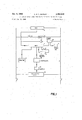
- FIGURE 1 is a block diagram of an electronic circuit for automatic timing apparatus according to the invention.
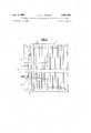
- FIGURE 2 is an elevation of a touch pad with the waterproof cover removed
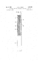
- FIGURE 3 is a part sectional end view of FIGURE 2
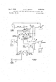
- FIGURE 4 is a block diagram of an alternative electronic circuit for automatic timing apparatus.
- FIGURE 1 12 volt Direct Current bus bars 1 and 2 supply power to the circuit.
- a one megacycle crystal oscillator 3 produces an oscillating signal as soon as the bus bars are energised.
- Digital timers 4 one only being shown in the drawings are provided one for each lane of the pool.
- a push button 5 is provided to connect a start relay 6 to the bus bars, a contact 7 being controlled by the relay 6.
- the contact 7 connects a start power unit 8 to the bus bars.
- the unit is effective, through closed switch contacts in the digital timers 4, to connect the timers to the oscillator 3 and to supply power to percussion start units 9, which units 9 are provided one in the starting block of each lane of the swimming pool.
- a touch pad 10 contains contacts which, when closed disconnect the timer 4 from the oscillator 3.
- the timer 4 is connected to a printer 11 and to a serialiser 12, the timer and serialiser being either directly connected or connected as shown through manually operable switches 14 to an indicating unit 15.
- a manually operated switch 16 may be provided to prevent the contacts in the touch pad from disconnecting the timer 4 from the oscillator 3.
- the touch paid 10 is illustrated with reference to FIG- URES 2 and 3 of the drawings and comprises a metal frame 17, having a series of elongated tensioned contacts 18, suspended across the frame in a substantially vertical direction.
- the assembly of frame 17, contacts 18, plate 19 and block 20, is enclosed by a flexible waterproof cover 22, advantageously of a rubber or synthetic plastic composition.
- the elongated contacts 18 are advantageously provided as close coiled cadmium-plated steel springs, and are secured to the frame 17 by means of eyelets screwed into the ends of the springs, the eyelets hooking over screws provided in the frame 17.
- the touch pads are secured to the end of the swimming pool in a partially submerged vertical orientation, one in the centre of each lane of the pool.
- the presence of the fluid 23 prevents the contacts being operated by the hydrostatic pressure due to the partial immersion of the touch pad in the water.
- One touch pad for each swimming lane may be provided at one end of the pool and connected as shown in FIGURE 1.
- a touch pad maybe provided at each end of the pool the second pad being connected in parallel with the first pad.
- the competitors in the race stand one at the end of each lane, on individual starting blocks, and the starter starts the race by pressing the start push button 5.
- the start relay 6 is thus energised, closing contact 7 and connecting the start power unit 8 to the bus bars.
- the start power unit simultaneously supplies power to the percussion start instrument 9 and connects the timers 4 to the oscillator 3.
- the timers 4 are thus started at the same instant as the percussion instruments 9 given an audible start signal.
- Each competitor has an individual percussion instrument 9 mounted within his starting block and thus unfair advantages due to positioning are avoided.
- the switch 16 is left open on any touch pad which will be touched during the course of the race and may be closed by the judges when each swimmer is on his last lap. The swimmers are thereby prevented from stopping their timers part way through the race. Also if the judges wish to disqualify a competitor for any reason, they merely have to open the switch 16 on his timer and thus prevent his time being recorded and indicated.
- the elongated spring contacts 18 provided within the touch pads are under slight tenison and thus cannot be operated by any Waves in the swimming pool, but the force of a swimmer touching the pad with his hand is sufficient to cause the contacts 18 to touch the plate 19, and to close the circuit between the touch pad power supply 11 and the timer 4, thus stopping the timer.
- the touch pads are provided in recesses in the end of the swimming pool in such manner that, when in position, the outer surface of each pad which is touched by the swimmer projects from the end wall of the pool a distance equal to the distance the contacts 18 must be moved to contact the plate 19.
- the serializer is efiective to arrange the signals from the timers in order of the duration of connection of each of the timers with the oscillator, and after scrutiny or manual setting by the judges of the unit 14 the display unit 15 provides a visible indication as to which of the competitors is the winner of the race.
- FIGURE 4 three power supplies S S and S are provided to supply power to the circuit. Closing of the manually operated start contact 24 causes power from S to close a contact in a start relay 25.
- the start relay 25 simultaneously connects the digital timers 26 to an oscillator 27 and sounds off a percussion instrument 28 in the starting block of each lane of the swimming pool.
- the start relay also provides a delayed pulse to a lap counter 29 and this pulse also changes over a switch 30, to the other position to that shown, to feed the circuit with power from the second supply S
- the oscillator 27 is continuously fed with power at all times.
- the successive touchings of touch pads 31 and 32 by a swimmer in a multi-lap race operate a run down counter in the lap counter 29 and on the last lap the touching of the touch pad disconnects the timer 26 from he oscillator 27, the result being printed andindicated by a printer 33 and display 34 respectively.
- start is not a correct start, that is to say if contacts in a pad 35 on the top of a starting block or contacts in a rail 36 near the waterline at a starting position are opened before the start signal is given, then an indication of a false start is given by a device 37 which operates a rope dropping device 38 and sounds a continuous recall note on the percussion instruments 28. An all clear indication is given by a device 3% in the case of a fair start.
- the contacts in the start block 35 must still be closed, by the weight of the swimmer next to swim, at the instant the contacts in a touch pad 31, 32 are closed by the swimmer finishing the preceding lap as if the contacts are not closed the device 37 is energized to disqualify that team from the race.
- the device 39 also gives a clear signal for a correct changeover in a relay race and a clear signal for a correct turn around in a multi-lay solo race.
- the circuit is also adapted for use as a training aid whereby swimmers can reduce their reaction time delays both on starting and on relay changeover.
- switches 41, 42 and 43 are moved to the other position to that shown in the figure, advantageously the switches are coupled, so that the timer 26 is coupled to the oscillator 27 simultaneously with the start signal but is uncoupled by way of the load 44- upon opening of the contacts in the block 35 or rail 36.
- the time delay in starting can thus be recorded, displayed and reduced by training.
- the timer can be started by a swimmer touching a touch pad 31,32 and can be stopped by opening of the contacts in the block 35 by way of the lead 44, the delay in relay changeover can thus be recorded, displayed and reduced by training.
- the delay, inherent in any relay, occurring in the start relay 25 occurs before either the start signal is given or the timers are started and that no other relays are operated during the timing sequences, the delay in which would cause an inaccuracy in the recorded time.
- Timingapparatus for swimming races comprising in combination a swimming pool having a plurality of lanes, a touch pad in each lane, a timer for each lane, an oscillator, an audible start signal at each lane, means for connecting said timers to said oscillator simultaneously with the sounding of the audible start signals, means for disconnecting the timer of each lane from the oscillator when a prescribed one of the touch pads in that lane is touched and means to display for how long each timer was connected to said oscillator.
- Timing apparatus for swimming races comprising in combination a swimming pool having a plurality of lanes, a touch pad at each end of each lane, a timer for each lane, an oscillator, means for connecting said timers to said oscillator simultaneously with the sounding of an audible start signal, means for disconnecting the timer of each lane from the oscillator when a prescribed one of the touch pads in that lane is touched and means to display for how long each timer Was connected to said oscillator.
- the touch pads comprise a pair of electrical contacts positioned at the finish position of the race, which contacts are closed by a. competitor touching the touch pad as he completes the race.
- the false start means comprise a pair of electrical contacts which are operated by a competitor leaving a starting box provided at one end of a swimming pool, operation of the contacts before a start signal is given being effective to give a false start indication.
- the false start means comprise a pair of electrical contacts which are operated by a competitor leaving a rail provided just above the water level at one end of the swimming pool, operation of the contacts before a start signal is given being effective to give a false start indication.
- Timing apparatus in which a serializer is provided to arrange the times during which each of said timers was connected to said oscillator in ascending order of magnitude, display means being provided to give a visual indication of the magnitude and order of the times and thus indicate the winner and duration of the race.
- said touch pad comprises elongated resilient members spaced apart from a plate member, the elongated members being adapted, upon pressure being applied thereto, as by a competitor finishing a race, to move into electrical contact with the plate member.
- Timing apparatus in which the elongated resilient members and the plate member are contained within an envelope of flexible insulating material, a liquid being provided Within the envelope to componsate for hydrostatic pressure if the envelope is immersed in water.
Landscapes
- Measurement Of Unknown Time Intervals (AREA)
Description
Jan. 9, 1968 ,c. G. L. MORLEY 3,363,243
ELECTRONIC SWIM TIMER CONTROLLED BY TOUCH PAD IN SWIM LANE Fil ed Jan. 15, 1965 4 Sheets-Sheet 1 OSC.
CONTACT R swncH H 2 PRINTER v .--$ERIAL|ZER 2 4 l4 SWITCH i .5 lND|CATlNG UNIT C. G. L. MORLEY Jan. 9, 19 8 ELECTRONIC SWIM TIMER CONTROLLED BY TOUCH PAD IN SWIM LANE v 4 Sheets-Sheet 2 Filed Jan. 15, 1965 Jan. 9, 1968 c.. G. MORLEY 3,363,243
' ELECTRONIC SWIM TIMER CONTROLLED BY TOUCH PAD I N SWIM LANE 4 Sheets-Sheet 3" Filed Jan. l5,'l96 5 F'IC5.3.
Jan. 9, 1968 Filed Jan. l5, 1965 C. G. L. MORLEY ELECTRONIC SWIM TIMER CONTROLLED BY TOUCH PAD IN SWIM LANE 4 Sheets-Sheet 4 24 42 gTART 27 0-H ELAY osc.
PQWER SUPPLY CONTACT swwcueu -o TIMER S2 z-Pnmrsn 232:3 FAIR 39 START SIGNAL 45 DISPLAY CONTACT (EQAJNTER SWITCHES J FIG 4 4! POWER SUPPLY United States Patent ELECTRONIC SWIM TIMER CONTROLLED BY TOUCH PAD 1N SWIM LANE Cyril George Lidstone Morley, Harrow, England, assignor, by mesne assignments, to The National Research Development Corporation, London, England, a corporation of the United Kingdom Filed Jan. 15, 1965, Ser. No. 425,793 Claims. (Cl. 340-423) The invention relates to timing apparatus for races and particularly to electronic timing apparatus for swimming races.
Known timing apparatus for swimming races has the disadvantage that, even though the apparatus itself may be accurate, it must be started and stopped manually and errors occur due to variations in the reaction times of the judges of the race.
Where a race has a close finish the judges may have to wait for a photograph of the finish to be developed before the result can be determined and announced. Also it is difficult for the judges to determine whether or not a swimmer leaves the start position before the starting signal is given both at the beginning of races and during changeovers in relay races.
A further disadvantage of known starting and timing methods is that the competitors, when on their starting blocks, are not at equal distances from the instrument which gives the audible start signal, and thus, due to the low speed of sound, receive the start signal after different intervals. With a pool width of 35 yards the difference in the time between the sound signal reaching two competitors in a swimming race could be as much as one tenth of a second.
The invention has among its objects to mitigate these disadvantages and to provide automatic timing means for timing races.
According to the invention automatic timing apparatus for races comprises an oscillator, a timer for each competitor in the race, means for connecting each of the timers to the oscillator when a start signal is given, and means for disconnecting each timer from the oscillator upon the corresponding competitor reaching the finishing position of the race.
According to the invention furthermore, the automatic timing apparatus may be provided for timing races in swimming pools and may comprise switch means effective to connect electrically operated means to a power source, the electrically operated means being effective to operate percussion apparatus provided in or near each of a plurality of starting blocks, a starting block being provided in each lane of the swimming pool, the percussion apparatus providing an individual audible start signal to each competitor in the race, the switch means being also effective to connect timers to an oscillator, which oscillator is adapted to supply high frequency pulses to operate the timers until disconnected therefrom by further switch means operated by the competitors and provided at the finishing position in each lane of the swimming pool.
The further switch means may comprise a pair of contacts provided in waterproof pads which pads are provided at each end of each swimming lane of a swimming pool, so that closure of the further switch means is effective to disconnect the associated timer from the oscillator and to cause the timer to transmit a signal to serializer means, the serializer means being effective to process the signals from the timers and to arrange them in ascending order of the duration of connection of each of the timers with the oscillator.
Automatic or manually operated means may be pro- 3,363,243 Patented Jan. 9, 1968 vided for indicating the sequence in which the competitors have completed the race and the time that each competitor has taken.
According to the invention moreover the automatic timing means may include false start means provided at the position at which each competitor starts the race, which false start means are effective to indicate whether or not the competitor leaves the start position before the start signal is given.
Thus the false start means may include a .pad containing a pair of contacts, the pad being positioned in the top surface of the block on which the swimmer stands, and from which block he dives at the start of the race.
Alternatively, the false start means may include a hinged platform provided on the starting block on which the swimmer stands and from which he dives to start a race, the hinged platform being used to actuate appropriate contacts when the swimmer is either standing on, or has left the starting block. As an alternative to the use of switches or contacts, a proximity detecting device could be used.
According to the invention still further the false start means may be provided in a rail positioned parallel to and above the surface of the water so that a false start may be detected in backstroke races where the swimmer starts the race already partly immersed in the water.
The false start means are advantageously effective to give an all-clear signal if the swimmer leaves the pad after the start signal is given, but if the swimmer leaves the pad before the start signal is given then the false start means causes an electrical start signal pulse provided by the starter to give an alarm indication, for example, to create a continuous audible signal and to drop a false start rope across the lanes of the swimming pool.
The false start means are also applicable in relay races, to cause an incorrect changeover signal to be given if a swimmer, on a subsequent stage of a relay, leaves the start position before the swimmer in the immediately previous stage has completed that stage by touching the touch pad provided at the end of the swimming pool.
The invention is diagrammatically illustrated by way of example in the accompanying drawings, in which:
FIGURE 1 is a block diagram of an electronic circuit for automatic timing apparatus according to the invention;
FIGURE 2 is an elevation of a touch pad with the waterproof cover removed;
FIGURE 3 is a part sectional end view of FIGURE 2, and
FIGURE 4 is a block diagram of an alternative electronic circuit for automatic timing apparatus.
Referring to the drawings, as shown in FIGURE 1, 12 volt Direct Current bus bars 1 and 2 supply power to the circuit. A one megacycle crystal oscillator 3 produces an oscillating signal as soon as the bus bars are energised. Digital timers 4 one only being shown in the drawings are provided one for each lane of the pool.
A push button 5 is provided to connect a start relay 6 to the bus bars, a contact 7 being controlled by the relay 6. The contact 7 connects a start power unit 8 to the bus bars. The unit is effective, through closed switch contacts in the digital timers 4, to connect the timers to the oscillator 3 and to supply power to percussion start units 9, which units 9 are provided one in the starting block of each lane of the swimming pool.
A touch pad 10 contains contacts which, when closed disconnect the timer 4 from the oscillator 3. The timer 4 is connected to a printer 11 and to a serialiser 12, the timer and serialiser being either directly connected or connected as shown through manually operable switches 14 to an indicating unit 15. A manually operated switch 16 may be provided to prevent the contacts in the touch pad from disconnecting the timer 4 from the oscillator 3.
The touch paid 10 is illustrated with reference to FIG- URES 2 and 3 of the drawings and comprises a metal frame 17, having a series of elongated tensioned contacts 18, suspended across the frame in a substantially vertical direction. A vertical metal plate 19, advantageously of stainless steel, is provided spaced a distance behind the contacts 18, the plate being mounted on an inflexible insulating block 20, of substantially the same size as the frame 17, and secured at its edges to the frame 17 as by screws 21. The assembly of frame 17, contacts 18, plate 19 and block 20, is enclosed by a flexible waterproof cover 22, advantageously of a rubber or synthetic plastic composition.
An insulating fluid 23, advantageously of a silicone composition, is provided to surround the contacts 18, the level of the fluid being indicated in a sight glass 24. The elongated contacts 18 are advantageously provided as close coiled cadmium-plated steel springs, and are secured to the frame 17 by means of eyelets screwed into the ends of the springs, the eyelets hooking over screws provided in the frame 17.
The touch pads are secured to the end of the swimming pool in a partially submerged vertical orientation, one in the centre of each lane of the pool. The presence of the fluid 23 prevents the contacts being operated by the hydrostatic pressure due to the partial immersion of the touch pad in the water. One touch pad for each swimming lane may be provided at one end of the pool and connected as shown in FIGURE 1. Alternatively a touch pad maybe provided at each end of the pool the second pad being connected in parallel with the first pad.
In operation of the apparatus the competitors in the race stand one at the end of each lane, on individual starting blocks, and the starter starts the race by pressing the start push button 5. The start relay 6 is thus energised, closing contact 7 and connecting the start power unit 8 to the bus bars. The start power unit simultaneously supplies power to the percussion start instrument 9 and connects the timers 4 to the oscillator 3. The timers 4 are thus started at the same instant as the percussion instruments 9 given an audible start signal.
Each competitor has an individual percussion instrument 9 mounted within his starting block and thus unfair advantages due to positioning are avoided. The switch 16 is left open on any touch pad which will be touched during the course of the race and may be closed by the judges when each swimmer is on his last lap. The swimmers are thereby prevented from stopping their timers part way through the race. Also if the judges wish to disqualify a competitor for any reason, they merely have to open the switch 16 on his timer and thus prevent his time being recorded and indicated.
The elongated spring contacts 18 provided within the touch pads are under slight tenison and thus cannot be operated by any Waves in the swimming pool, but the force of a swimmer touching the pad with his hand is sufficient to cause the contacts 18 to touch the plate 19, and to close the circuit between the touch pad power supply 11 and the timer 4, thus stopping the timer. The touch pads are provided in recesses in the end of the swimming pool in such manner that, when in position, the outer surface of each pad which is touched by the swimmer projects from the end wall of the pool a distance equal to the distance the contacts 18 must be moved to contact the plate 19.
As soon as the timer 4 is stopped, it feeds a signal to the printer 11 and to the serializer 12. The serializer is efiective to arrange the signals from the timers in order of the duration of connection of each of the timers with the oscillator, and after scrutiny or manual setting by the judges of the unit 14 the display unit 15 provides a visible indication as to which of the competitors is the winner of the race.
In the embodiment illustrated in FIGURE 4 three power supplies S S and S are provided to supply power to the circuit. Closing of the manually operated start contact 24 causes power from S to close a contact in a start relay 25. The start relay 25 simultaneously connects the digital timers 26 to an oscillator 27 and sounds off a percussion instrument 28 in the starting block of each lane of the swimming pool.
The start relay also provides a delayed pulse to a lap counter 29 and this pulse also changes over a switch 30, to the other position to that shown, to feed the circuit with power from the second supply S The oscillator 27 is continuously fed with power at all times. The successive touchings of touch pads 31 and 32 by a swimmer in a multi-lap race operate a run down counter in the lap counter 29 and on the last lap the touching of the touch pad disconnects the timer 26 from he oscillator 27, the result being printed andindicated by a printer 33 and display 34 respectively. If the start is not a correct start, that is to say if contacts in a pad 35 on the top of a starting block or contacts in a rail 36 near the waterline at a starting position are opened before the start signal is given, then an indication of a false start is given by a device 37 which operates a rope dropping device 38 and sounds a continuous recall note on the percussion instruments 28. An all clear indication is given by a device 3% in the case of a fair start.
In a changeover in a relay race the contacts in the start block 35 must still be closed, by the weight of the swimmer next to swim, at the instant the contacts in a touch pad 31, 32 are closed by the swimmer finishing the preceding lap as if the contacts are not closed the device 37 is energized to disqualify that team from the race. The device 39 also gives a clear signal for a correct changeover in a relay race and a clear signal for a correct turn around in a multi-lay solo race.
The circuit is also adapted for use as a training aid whereby swimmers can reduce their reaction time delays both on starting and on relay changeover. For this purpose switches 41, 42 and 43 are moved to the other position to that shown in the figure, advantageously the switches are coupled, so that the timer 26 is coupled to the oscillator 27 simultaneously with the start signal but is uncoupled by way of the load 44- upon opening of the contacts in the block 35 or rail 36. The time delay in starting can thus be recorded, displayed and reduced by training. Similarly by means of a load 45 the timer can be started by a swimmer touching a touch pad 31,32 and can be stopped by opening of the contacts in the block 35 by way of the lead 44, the delay in relay changeover can thus be recorded, displayed and reduced by training.
It should be noted that the delay, inherent in any relay, occurring in the start relay 25 occurs before either the start signal is given or the timers are started and that no other relays are operated during the timing sequences, the delay in which would cause an inaccuracy in the recorded time.
I claim:
1. Timingapparatus for swimming races comprising in combination a swimming pool having a plurality of lanes, a touch pad in each lane, a timer for each lane, an oscillator, an audible start signal at each lane, means for connecting said timers to said oscillator simultaneously with the sounding of the audible start signals, means for disconnecting the timer of each lane from the oscillator when a prescribed one of the touch pads in that lane is touched and means to display for how long each timer was connected to said oscillator.
2. Timing apparatus for swimming races comprising in combination a swimming pool having a plurality of lanes, a touch pad at each end of each lane, a timer for each lane, an oscillator, means for connecting said timers to said oscillator simultaneously with the sounding of an audible start signal, means for disconnecting the timer of each lane from the oscillator when a prescribed one of the touch pads in that lane is touched and means to display for how long each timer Was connected to said oscillator.
3. Timing apparatus according to claim 2, in which the touch pads comprise a pair of electrical contacts positioned at the finish position of the race, which contacts are closed by a. competitor touching the touch pad as he completes the race.
4. Timing apparatus according to claim 2, in which false start means are provided at positions at which each competitor starts the race, which false start means are effective to indicate Whether or not the competitor leaves the start position before the start signal is given.
5. Timing apparatus according to claim 4, in which the false start means comprise a pair of electrical contacts which are operated by a competitor leaving a starting box provided at one end of a swimming pool, operation of the contacts before a start signal is given being effective to give a false start indication.
6. Timing apparatus according to claim 4, in which the false start means comprise a pair of electrical contacts which are operated by a competitor leaving a rail provided just above the water level at one end of the swimming pool, operation of the contacts before a start signal is given being effective to give a false start indication.
7. Timing apparatus according to claim 2, in which a serializer is provided to arrange the times during which each of said timers was connected to said oscillator in ascending order of magnitude, display means being provided to give a visual indication of the magnitude and order of the times and thus indicate the winner and duration of the race.
8. Timing apparatus according to claim 2, in which said touch pad comprises elongated resilient members spaced apart from a plate member, the elongated members being adapted, upon pressure being applied thereto, as by a competitor finishing a race, to move into electrical contact with the plate member.
9. Timing apparatus according to claim 8, in which the elongated resilient members and the plate member are contained within an envelope of flexible insulating material, a liquid being provided Within the envelope to componsate for hydrostatic pressure if the envelope is immersed in water.
10. Timing apparatus for timing races in swimming pools comprising switch means effective to connect electrically operated means to a power source, the electrically operated means being effective to operate percussion apparatus provided in or near each of a plurality of starting blocks, a starting block being provided in each lane of the swimming pool, the percussion apparatus providing an individual audible start signal to each competitor in the race, the switch means being also effective to connect timers to an oscillator, which oscillator is adapted to supply high frequency pulses to operate the timers until disconnected therefrom by further switch means operated by the competitors and provided at the finishing position in each lane of the swimming pool.
References Cited UNITED STATES PATENTS 2,165,749 7/1939 Engholm et al. 340-323 2,180,448 11/1939 Williams 273-86.2 2,318,450 5/1943 Belock 340323 2,322,936 6/1943 Hite 340-323 2,497,541 2/1950 Ferrara 340-323 2,547,332 4/1951 Loveless et al 340323 3,091,458 5/1963 Becks 340-323 X THOMAS B. HABECKER, Primary Examiner.
NEIL C. READ, Examiner.
I. 3. LEVIN, H. I. PITTS, Assistant Examiners.
Claims (1)
1. TIMING APPARATUS FOR SWIMMING RACES COMPRISING IN COMBINATION A SWIMMING POOL HAVING A PLURALITY OF LANES, A TOUCH PAD IN EACH LANE, A TIMER FOR EACH LANE, AN OSCILLATOR, AN AUDIBLE START SIGNAL EACH LANE, MEANS FOR CONNECTING SAID TIMERS TO SAID OSCILLATOR SIMULTANEOUSLY WITH THE SOUNDING OF THE AUDIBLE START SIGNALS, MEANS FOR DIS-
Priority Applications (1)
| Application Number | Priority Date | Filing Date | Title |
|---|---|---|---|
| US425793A US3363243A (en) | 1965-01-15 | 1965-01-15 | Electronic swim timer controlled by touch pad in swim lane |
Applications Claiming Priority (1)
| Application Number | Priority Date | Filing Date | Title |
|---|---|---|---|
| US425793A US3363243A (en) | 1965-01-15 | 1965-01-15 | Electronic swim timer controlled by touch pad in swim lane |
Publications (1)
| Publication Number | Publication Date |
|---|---|
| US3363243A true US3363243A (en) | 1968-01-09 |
Family
ID=23688067
Family Applications (1)
| Application Number | Title | Priority Date | Filing Date |
|---|---|---|---|
| US425793A Expired - Lifetime US3363243A (en) | 1965-01-15 | 1965-01-15 | Electronic swim timer controlled by touch pad in swim lane |
Country Status (1)
| Country | Link |
|---|---|
| US (1) | US3363243A (en) |
Cited By (12)
| Publication number | Priority date | Publication date | Assignee | Title |
|---|---|---|---|---|
| US3631453A (en) * | 1970-08-21 | 1971-12-28 | Data Time | Timer start-stop apparatus |
| US3665452A (en) * | 1970-03-16 | 1972-05-23 | William T Maccreadie | Starting-timing device for swimming, track and field |
| US3678496A (en) * | 1970-04-20 | 1972-07-18 | Data Time | Touch-operated signal producer |
| US3784768A (en) * | 1972-02-28 | 1974-01-08 | Data Time | Submersible touch-operated signaler with fluid drainage passages |
| US4006364A (en) * | 1974-10-16 | 1977-02-01 | Societe Suisse Pour L'industrie Horlogere Management Services S.A. | Touch pad arrangement for signalling arrivals in swimming competitions |
| US4027875A (en) * | 1975-04-23 | 1977-06-07 | Carson Monroe Hurley | Recation speed training device |
| US4577859A (en) * | 1983-09-30 | 1986-03-25 | Gossett Burnham N | In-place swimming apparatus |
| US4700369A (en) * | 1986-01-28 | 1987-10-13 | Joseph Siegal | Athletic activities counter |
| US5285428A (en) * | 1991-11-15 | 1994-02-08 | Eric Rosow | Swimmer's lap counter |
| EP0918304A1 (en) * | 1997-11-20 | 1999-05-26 | Seiko Instruments Inc. | Clocking device for swimming race |
| US20090185455A1 (en) * | 2008-01-23 | 2009-07-23 | Colorado Time Systems, Llc | Aquatic Event Timer Apparatus and Methods |
| US10751570B2 (en) | 2017-07-26 | 2020-08-25 | Jeffrey J. Karc | Athletic speed and time measurement device and methods of making and using same |
Citations (7)
| Publication number | Priority date | Publication date | Assignee | Title |
|---|---|---|---|---|
| US2165749A (en) * | 1935-11-19 | 1939-07-11 | Jacobsens Elek Ske Vaerksted A | Arrangement for controlling the start in race courses |
| US2180448A (en) * | 1934-02-15 | 1939-11-21 | Frederick W Williams | Amusement device |
| US2318450A (en) * | 1938-06-09 | 1943-05-04 | American Teletimer Corp | Timing system |
| US2322936A (en) * | 1941-01-27 | 1943-06-29 | Robert M Hite | Starting barrier |
| US2497541A (en) * | 1950-02-14 | Race timing system | ||
| US2547332A (en) * | 1949-09-23 | 1951-04-03 | Electric Eye Equipment Company | Device for starting races |
| US3091458A (en) * | 1962-03-19 | 1963-05-28 | Cleveland Trust Co | Bowling game apparatus |
-
1965
- 1965-01-15 US US425793A patent/US3363243A/en not_active Expired - Lifetime
Patent Citations (7)
| Publication number | Priority date | Publication date | Assignee | Title |
|---|---|---|---|---|
| US2497541A (en) * | 1950-02-14 | Race timing system | ||
| US2180448A (en) * | 1934-02-15 | 1939-11-21 | Frederick W Williams | Amusement device |
| US2165749A (en) * | 1935-11-19 | 1939-07-11 | Jacobsens Elek Ske Vaerksted A | Arrangement for controlling the start in race courses |
| US2318450A (en) * | 1938-06-09 | 1943-05-04 | American Teletimer Corp | Timing system |
| US2322936A (en) * | 1941-01-27 | 1943-06-29 | Robert M Hite | Starting barrier |
| US2547332A (en) * | 1949-09-23 | 1951-04-03 | Electric Eye Equipment Company | Device for starting races |
| US3091458A (en) * | 1962-03-19 | 1963-05-28 | Cleveland Trust Co | Bowling game apparatus |
Cited By (12)
| Publication number | Priority date | Publication date | Assignee | Title |
|---|---|---|---|---|
| US3665452A (en) * | 1970-03-16 | 1972-05-23 | William T Maccreadie | Starting-timing device for swimming, track and field |
| US3678496A (en) * | 1970-04-20 | 1972-07-18 | Data Time | Touch-operated signal producer |
| US3631453A (en) * | 1970-08-21 | 1971-12-28 | Data Time | Timer start-stop apparatus |
| US3784768A (en) * | 1972-02-28 | 1974-01-08 | Data Time | Submersible touch-operated signaler with fluid drainage passages |
| US4006364A (en) * | 1974-10-16 | 1977-02-01 | Societe Suisse Pour L'industrie Horlogere Management Services S.A. | Touch pad arrangement for signalling arrivals in swimming competitions |
| US4027875A (en) * | 1975-04-23 | 1977-06-07 | Carson Monroe Hurley | Recation speed training device |
| US4577859A (en) * | 1983-09-30 | 1986-03-25 | Gossett Burnham N | In-place swimming apparatus |
| US4700369A (en) * | 1986-01-28 | 1987-10-13 | Joseph Siegal | Athletic activities counter |
| US5285428A (en) * | 1991-11-15 | 1994-02-08 | Eric Rosow | Swimmer's lap counter |
| EP0918304A1 (en) * | 1997-11-20 | 1999-05-26 | Seiko Instruments Inc. | Clocking device for swimming race |
| US20090185455A1 (en) * | 2008-01-23 | 2009-07-23 | Colorado Time Systems, Llc | Aquatic Event Timer Apparatus and Methods |
| US10751570B2 (en) | 2017-07-26 | 2020-08-25 | Jeffrey J. Karc | Athletic speed and time measurement device and methods of making and using same |
Similar Documents
| Publication | Publication Date | Title |
|---|---|---|
| US3363243A (en) | Electronic swim timer controlled by touch pad in swim lane | |
| US4780085A (en) | Lap timing device | |
| US2457968A (en) | Automatic pacing system | |
| JPS57108789A (en) | Timepiece device with game function | |
| US3678496A (en) | Touch-operated signal producer | |
| FR2282130A1 (en) | SOLID STATE ELECTRONIC WATCHMAKING DEVICE | |
| JPS5467797A (en) | Electronic apparatus | |
| JPS55106383A (en) | Electronic watch with alarm | |
| FR2313590A1 (en) | DEVICE FOR MECHANICAL REMOTE CONTROL | |
| FR2471016B1 (en) | SYSTEM FOR PERIODICALLY INVERTING THE ORDER OF VIDEO DATA IN AN ELECTRONIC DISPLAY DEVICE WITH A FLAT PANEL | |
| GB1024580A (en) | ||
| GB2254453A (en) | Swimming pool lap timer. | |
| US3263168A (en) | Stopping device for a time measuring apparatus, particularly for swimming races | |
| JP2756460B2 (en) | Swimming competition display system | |
| JPS53118165A (en) | Alarm time display device in alarm timepiece | |
| US2619170A (en) | Swimming race timer | |
| JPS53129682A (en) | Electronic apparatus provided with alarm functions | |
| CH617565B (en) | METHOD OF DISPLAYING TIME IN AN ELECTRONIC WATCH. | |
| JPS51145362A (en) | Time informing watch | |
| JPS5713389A (en) | Electronic wrist watch with scale generation mechanism | |
| JPS53133063A (en) | Electronic watch with alarm | |
| JPS6176980A (en) | Conference clock | |
| JPH0792508B2 (en) | Pace checker | |
| JPH0331452B2 (en) | ||
| JPS54145169A (en) | Watch apparatus |