US335273A - Oeville cooley - Google Patents
Oeville cooley Download PDFInfo
- Publication number
- US335273A US335273A US335273DA US335273A US 335273 A US335273 A US 335273A US 335273D A US335273D A US 335273DA US 335273 A US335273 A US 335273A
- Authority
- US
- United States
- Prior art keywords
- wheel
- disk
- clamping
- cooley
- cam
- Prior art date
- Legal status (The legal status is an assumption and is not a legal conclusion. Google has not performed a legal analysis and makes no representation as to the accuracy of the status listed.)
- Expired - Lifetime
Links
- 239000011230 binding agent Substances 0.000 description 10
- 210000000481 Breast Anatomy 0.000 description 2
- 229910001018 Cast iron Inorganic materials 0.000 description 2
- 238000010276 construction Methods 0.000 description 2
- 229920000136 polysorbate Polymers 0.000 description 2
- 230000000717 retained Effects 0.000 description 2
Images

Classifications
-
- A—HUMAN NECESSITIES
- A01—AGRICULTURE; FORESTRY; ANIMAL HUSBANDRY; HUNTING; TRAPPING; FISHING
- A01F—PROCESSING OF HARVESTED PRODUCE; HAY OR STRAW PRESSES; DEVICES FOR STORING AGRICULTURAL OR HORTICULTURAL PRODUCE
- A01F15/00—Baling presses for straw, hay or the like
- A01F15/08—Details
- A01F15/14—Tying devices specially adapted for baling presses
- A01F15/145—Twine knotters
Definitions
- My invention relates tocord-holders for grain-binders; and it consists of the devices and combination of devices hereinafter described, and particularly pointed out in the claim.
- the objects of my invention are to provide a simple and effective means for positively opcrating the cord-clamping disk and retaining it in place without the use of the springs, and
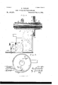
- FIG. l is an inverted plan or outer side View of a portion of a grain-binder, showing my improvement.
- Fig. 2 is a plan or inner 2:, side view of the same, showing the scroll-cam wheel in section; and
- Fig. 3 is a side face View of the scroll-cam wheel.
- B is the cast-iron frame for carrying the knotter, the holder,and co-operating parts.
- 0 is the breast plate secured to said frame.
- F is the knotter-driving shaft.
- A is the cam and gear wheel fixed on said shaft, and provided with a segment-gear, which at the proper time meshes with the pinion a of the knotter for driving the latter.
- G is the notched clamping-disk, pivoted on the plate I.
- H is the grooved holding-jaw cooperating with the disk G to hold the cord. It is pivoted to the frame, and is pressed toward said disk by the spring h.
- clamping-disk G is provided with the pinion g.
- F F are gear-wheels meshing together, and the former also meshing with the pinion g of Serial No. 136.103.
- the wheel Fis partly rotated at the proper time to actuate the wheel F and the clamping-disk by the following means:
- D is a plate or disk secured to the knotter driving-shaft E.
- D is, a cam disk-wheel mounted loosely on said shaft, and adj ustably secured to the plate D by means of the bolts K passing through the latter plate and through slots K in the wheel D.
- These bolts are pr0- vided with nuts, whereby the plate and wheel may be clamped together in different relative positions.
- This adjustable feature is for a purpose which will presently appear.
- the rib For the greater portion of its length the rib is concentric with the wheel; but its end portions are eccentric therewith, the portion (1 being brought nearer the center.
- the rib (I thus The thickness of the rib corresponds with the space be- So tween two adjacent teeth of the gear-wheel F, with which wheel said rib is always ongaged.
- the adjustable feature of the scroll-cam is for the purpose of taking up wear of the parts and adjusting the movement of the clamping-disk.
- the plate D, the ribbed wheel or scroll-cam-plate D, having the slots K, and the securing-bolts K substantially as and for the purpose set forth.
Description
2 Sheets-Sheet 1.
0. OOOLEY.
com) HOLDER FOR GRAIN BINDERS.
(No Model.)
No. 335,273. Patented Feb. 2, 1886.
N PETERS. mammo ram-r. Washinglun n. c
(No Model.) 2 Sheets-Sheet 2.
O. GOOLEY.
CORD HOLDER FOR GRAIN BINDERS.
Patented Feb. 2
UNITED STATES PATENT OFFICE.
ORVILLE COOLEY, OF BATAVIA, NEW YORK, ASSIGNOR TO THE JOHNSTON HARVESTER COMPANY, OF SAME PLACE.
CORD-HOLDER FOR GRAIN-BINDERS.
SPECIFICATION forming part of Letters Patent No. 335,273, dated February 2, 1886.
Application filed June 26, 1884.
To all whom it may concern:
Be it known that I, ORVILLE CooLnY, a citizen of the United States, residing at Batavia, in the county of Genesee and State of New York, have invented a new and useful Improvement in Cord-Holders for Grain-Binders, of which the following is a specification.
My invention relates tocord-holders for grain-binders; and it consists of the devices and combination of devices hereinafter described, and particularly pointed out in the claim.
The objects of my invention are to provide a simple and effective means for positively opcrating the cord-clamping disk and retaining it in place without the use of the springs, and
reduce friction by dispensing with a number of pieces heretofore used in connection with the cord-holding devices. I attain these objects by the mechanism illustrated in the accompanying drawings, in which- Figure l is an inverted plan or outer side View of a portion of a grain-binder, showing my improvement. Fig. 2 is a plan or inner 2:, side view of the same, showing the scroll-cam wheel in section; and Fig. 3 is a side face View of the scroll-cam wheel.
Like letters refer to like parts in all the fig ures.
As the improvement relates only to the manner of operating the cord-clamping disk, a description of the other portions of the binding mechanism will not be necessary further than to indicate some of the cooperating parts.
, B is the cast-iron frame for carrying the knotter, the holder,and co-operating parts. 0 is the breast plate secured to said frame.
F is the knotter-driving shaft. A is the cam and gear wheel fixed on said shaft, and provided with a segment-gear, which at the proper time meshes with the pinion a of the knotter for driving the latter.
G is the notched clamping-disk, pivoted on the plate I.
H is the grooved holding-jaw cooperating with the disk G to hold the cord. It is pivoted to the frame, and is pressed toward said disk by the spring h.
So far the construction is well known in the 50 Appleby type of machines.
In my improvement the clamping-disk G is provided with the pinion g.
F F are gear-wheels meshing together, and the former also meshing with the pinion g of Serial No. 136.103.
forms a helical orscroll-likc cam.
(No model.)
the clamping-disk. The wheel Fis partly rotated at the proper time to actuate the wheel F and the clamping-disk by the following means:
D is a plate or disk secured to the knotter driving-shaft E. D is, a cam disk-wheel mounted loosely on said shaft, and adj ustably secured to the plate D by means of the bolts K passing through the latter plate and through slots K in the wheel D. These bolts are pr0- vided with nuts, whereby the plate and wheel may be clamped together in different relative positions. This adjustable feature is for a purpose which will presently appear. On the side of the wheel D, at its periphery, is formed therib or flange d. This rib is not continuous, but is divided at one place, and its end portions, (1 d lap by each other, as shown, with a space between them equal to the thickness of one of the teeth on the wheel F. For the greater portion of its length the rib is concentric with the wheel; but its end portions are eccentric therewith, the portion (1 being brought nearer the center. The rib (I thus The thickness of the rib corresponds with the space be- So tween two adjacent teeth of the gear-wheel F, with which wheel said rib is always ongaged. By this means, when, by the rotation of the cam-wheel D, the eccentric portions (1 of the rib become engaged with the gearwheel, the latter will be partly rotated, and through the wheel F and pinion g the clamping-disk G will be moved the distance from one notch to the next for each revolution of the canrwheel D, and while the concentric o portion of said rib is engaged the gear-wheels, and consequently the clamping-disk, will be retained in position.
The adjustable feature of the scroll-cam, above described, is for the purpose of taking up wear of the parts and adjusting the movement of the clamping-disk.
Having thus described my invention, what I claim as new, and desire to secure by Letters Patent, is-
In combination with the clamping-disk and gear-wheels, the plate D, the ribbed wheel or scroll-cam-plate D, having the slots K, and the securing-bolts K, substantially as and for the purpose set forth.
\Vitnesses: ORVILLE COOLEY.
MILTON J. MooKFoRD, G. W. FORD.
IOO
Publications (1)
| Publication Number | Publication Date |
|---|---|
| US335273A true US335273A (en) | 1886-02-02 |
Family
ID=2404364
Family Applications (1)
| Application Number | Title | Priority Date | Filing Date |
|---|---|---|---|
| US335273D Expired - Lifetime US335273A (en) | Oeville cooley |
Country Status (1)
| Country | Link |
|---|---|
| US (1) | US335273A (en) |
-
0
- US US335273D patent/US335273A/en not_active Expired - Lifetime
Similar Documents
| Publication | Publication Date | Title |
|---|---|---|
| US335273A (en) | Oeville cooley | |
| US257837A (en) | John e | |
| US345674A (en) | cooley | |
| US334499A (en) | Grain-binder | |
| US308062A (en) | Cord-holder for grain-binders | |
| US366240A (en) | Grain-binder | |
| US566727A (en) | Binding mechanism for harvesters | |
| US771532A (en) | Knotter mechanism for grain-binders. | |
| US339994A (en) | Cord-holder for grain-binders | |
| US123967A (en) | Improvement in grain-binders | |
| US358919A (en) | Grain-binder | |
| US5916A (en) | Mill for breaking and grinding | |
| US264602A (en) | John f | |
| US328918A (en) | Coed holder foe self binders | |
| US222986A (en) | Improvement in sulky grain-binders | |
| US628071A (en) | Cord knotting and holding device for grain-binders. | |
| US215553A (en) | Improvement in grain-binders | |
| US331404A (en) | Joseph oscae jackmah | |
| US499838A (en) | Grain-binder | |
| US274772A (en) | howard | |
| US71660A (en) | Improvement in grain-binders | |
| US121290A (en) | Improvement in grain-binders | |
| US365044A (en) | Mechanism foe grain binders | |
| US317292A (en) | Grain-binder | |
| US609522A (en) | sharp |