US3341069A - Double row can vendor - Google Patents
Double row can vendor Download PDFInfo
- Publication number
- US3341069A US3341069A US563767A US56376766A US3341069A US 3341069 A US3341069 A US 3341069A US 563767 A US563767 A US 563767A US 56376766 A US56376766 A US 56376766A US 3341069 A US3341069 A US 3341069A
- Authority
- US
- United States
- Prior art keywords
- gate
- articles
- members
- stacks
- article
- Prior art date
- Legal status (The legal status is an assumption and is not a legal conclusion. Google has not performed a legal analysis and makes no representation as to the accuracy of the status listed.)
- Expired - Lifetime
Links
Images


Classifications
-
- G—PHYSICS
- G07—CHECKING-DEVICES
- G07F—COIN-FREED OR LIKE APPARATUS
- G07F11/00—Coin-freed apparatus for dispensing, or the like, discrete articles
- G07F11/02—Coin-freed apparatus for dispensing, or the like, discrete articles from non-movable magazines
- G07F11/04—Coin-freed apparatus for dispensing, or the like, discrete articles from non-movable magazines in which magazines the articles are stored one vertically above the other
- G07F11/16—Delivery means
- G07F11/24—Rotary or oscillatory members
Definitions
- the present invention relates to vending machines and more particularly to a vending mechanism arranged to vend articles from respective ones of tandem front and back positioned vertical stacks of articles in a vertical column of articles.
- Vending machines for vending articles from respective .ones of a plurality of vertically stored columns of articles are well known.
- Machines having vertical article storage columns arranged to stack articles in two vertical front and back tandem positioned stacks for each column are also known and the customary vending arrangement for such machines usually provides for the alternate successive release of articles from each front and back tandem stack for each successive vending operation from a particular column of articles.
- Another important object of the present invention is to provide a simple modified arrangement of a previously known gate mechanism to be adapted to vend articles alternately from two tandem arranged vertical stacks of articles in a single storage column.
- the vending machine is provided with one or more storage columns each adapted to contain vertically stacked articles to be vended and each column is deep enough to contain two tandem arranged front and back vertical stacks of articles of appropriate dimensions.
- a pair of gate members in a similar arrangement to that previously described in US. Patent 3,118,567 are movably positioned at the lower end of each column to have a normal article supporting or retaining position extending from front to back on each side of the column beneath the lowermost articles in the vertical stacks of articles.
- the gate members are movable to outer positions that are out of supporting engagement with the articles to permit the lowermost article in the column to drop to a vending position. Also in a. similar manner to that described in the previously mentioned US.
- suitable lowering paltform means is provided beneath the gate members to be raised to an article supporting position to receive the lowermost article moved past the gate members when the gate members are moved to their outer positions and thereby prevent the cascading of the entire vertical column of articles.
- the lowering platform means is arranged to drop and release or vend the lowermost article supported in vending position thereon as the gate members are moved back into supporting position beneath the next lowermost articles in the vertical column of articles at the end of each vending operation.
- a feature of the present invention is the provision of a respective movable shield member having a normal position overlying one gate member in article supporting relation underneath one tandem vertical stack of articles that may be towards the front of the storage column.
- another respective movable shield member having a normal position overlying the other gate member in article supporting relation is positioned underneath the other tandem vertical stack of articles that may be toice wards the rear of the storage column.
- Alternator coupling means is provided to alternately couple first one shield member to its underlying gate member and then the other shield member to its underlying gate member for simultaneous alternate movement with the respective gate member whereby articles are alternately supported and successively released by the respective shield members from the front and back tandem vertical stacks of articles during each successive vending operation.
- FIGURE 1 is a simplified front elevational view of the gate mechanism for a single vertical column of articles
- FIG. 2 is a fragmentary view, partly in section, of the lower end of a vending machine showing the gate mechanism and the lowering platforms for a single column of two vertical stacks of articles in tandem relation to be vended;
- FIG. 3 is a fragmentary view similar to FIG. 2, but showing the lowering platform in the raised position and an article supported in vending position thereon during the first part of the vending cycle;
- FIG. 4 is an enlarged side view, partly in section, showing details of the gate mechanism of the invention at the lower end of a vertical column of two stacks of articles to be vended;
- FIG. 5 is a plan view taken on the line V-V of FIG. 4;
- FIG. 6 is an enlarged sectional view taken on the line VI-VI of FIG. 5 showing the details of the alternator coupling mechanism together with the gate members and overlying shield members;
- FIG. 7 is a view similar to FIG. 6, but showing the alternator mechanism in the position assumed as the gate members are being moved out to a vending position;
- FIG. 8 is a view similar to FIG. 7, but shOWing the interengaging relation of the alternator members in the positions assumed just before the gate members are moved to their fully outer positions for releasing the lowermost article in a stack of articles;
- FIG. 9 is a view similar to FIGS. 6, 7 and 8 except showing the alternator mechanism and the gate and shield members in the positions assumed as they are returned to the article supporting relation beneath the next lowermost article in the vertical column as the lowermost article shown in FIG. 8 is released from the lowering platform and vended.
- FIGS. 1, 2 and 3 of the drawings it should be understood that for purposes of simplifying the drawings and the description of the invention the mechanism for vending articles from only a single vertical storage column is shown, but that duplicate mechanisms may be provided under a plurality of side-by-side vertical storage columns in an arrangement similar to that shown in the previously mentioned US. Patent 3,118,567. Although as shown by FIGS.
- the single lifting plate 10 is shown to be connected to the lever end 11 of the bell crank 12 which is pivotally mounted at 13 to an end wall of the machine.
- the ball crank 12 is pivotally connected at 14 to a reciprocating link 15 which is reciprocated by the movement of the connecting link 16 coupled to the crank 17 of a one revolution vend shaft or motor 18. It will be understood that for each vending operation the shaft or motor 18 is moved through a single revolution to reciprocate the connecting bar 15 and raise and lower the lifter plate 10 during a vending operation.
- lowering platform means which may comprise the crank arms 19 and 20 pivoted at 21 and 22 respectively, are raised to support any articles being vended during the vending operation and prevent cascading of either tandem stack of the entire vertical stored column of articles at the time that the gate mechanism, to be described, is opened to permit movement of an article such as shown at A in FIG. 3 of the drawing to a vending position as shown by FIG. 4 to be supported on the rods 23 and 24 of the lowering crank arm 20.
- a platform comprising a screen or similar sheet material (not shown) may be supported on the upper surface of the platform rods 23, 24 in a manner similar to that shown in the previously mentioned Patent 3,118,567 for preventing unauthorized access to the column stacks during vending.
- the gate mechanism is moved back into position beneath the next lowermost articles in the columns of articles and the lowering platform arms 19 and 20 are again lowered to their position shown by FIG. 2 of the drawings allowing any articles previously supported thereon in vending position to be dropped down to a vending chute not shown.
- a pair of toggle links 25 and 26 are pivotally connected between the vertically movable lifter 10 and respective ends of the pivotal arms 27, 28.
- FIGS. 2 and 4 of the drawings the vertical column is deep enough to contain two tandem positioned stacks of articles to be vended with lowermost articles such as shown at A and B.
- These articles may be cylindrical articles such as cans or bottles although they may have other various shapes as may be suitable to be vended.
- a pivotal shield member 31 is normally positioned to overlie the gate member or bar 29 beneath the lowermost article B in the rearward stack of tandem arranged stacks of articles.
- a pivotal shield member 32 is normally positioned to overlie the other gate member 30 beneath the lowermost article A in the forward stack of articles in the vertical column of tandem stacked articles.
- the lifter plate or slide 10 is provided with a stop member 33 engaging a stationary frame member 34 of the machine to which the gate member pivotal arms 27 and 28 and the shield members 31 and 32 are pivotally attached.
- the stop member 33 on the slide lifter 10 serves to normally maintain the gate members or bars 29 and 30 together with their overlying shield members 31 and 32 in the article supporting position shown by FIG. 4 of the drawing.
- Alternator coupling means is provided within the housing at an intermediate position beneath the forward and rearward tandem stacks of articles to be vended.
- the details of the alternator coupling mechanism contained within the housing 40 are shown together with the mode of operation thereof by FIGS. 6-9 of the drawings and will now be described in detail.
- Each shield member 31 and 32 is pivotally mounted at 41 and 42 respectively to the same respective pivot points for the gate member pivotal arms 27 and 28 which are located intermediate the length of the gate bars 29 and 30, more clearly shown by FIGS. 4 and 5 of the drawings.
- the shield member 31 normally overlies the gate member rod 29 and engages in supporting relation the lowermost article B of the rear stack of articles while the shield member 32 normally overlies the gate member rod 30 and engages in supporting relation the lowermost article A in the front stack of articles to be vended.
- the alternator coupling member means includes a respective hook member 44 pivotally mounted at 45 on the shield member 31 and the hook member 46 pivotally mounted at 47 on the hook member 32.
- the hook member 44 is provided with a hook surface 47 adapted to be received in the hook recess 48 of the gate member or bar 29.
- the hook member 46 is provided with a hook end 49 adapted to be received in the hook receiving recess 50 of the gate member or bar 30.
- Interengaging end surfaces 51 and 52 of the hook members 44, 46 engage each other respectively during each vending operation in a manner to alternately engage the hook end 47 with the gate bar 29 and the hook end 49 with the gate bar 30.
- each successive vending operation will alternately move either the shield 31 with the gate member 29 to vend article B or the shield member 32 with the gate member bar 30 to vend article A.
- FIG. 6 of the drawings shows the alternator coupling mechanism in the positions assumed at the end of a vending operation in condition for a next subsequent vending operation that will be effective to vend article A from the forward stack of tandem arranged stacks of articles to be vended.
- the hook end 49 is received in the hook recess 50 of the gate bar 30 while the hook end 47 is disengaged from the gate bar 29.
- the shield 32 will be moved together with the gate member 30 while the shield 31 will remain in its normal position in supporting relation beneath the article B in the rear stack of articles.
- article A is allowed to move downward as shown by FIGS. 7 and 8 of the drawings to the raised lowering platform as shown by FIG. 3 of the drawings.
- the interengaging end surfaces 51 and 52 of the respective hook members 44 and 46 will assume first the position shown by FIG. 7 of the drawings and then the position shown by FIG. 8 of the drawings.
- the gate members or bars 29 and 30 move back in the direction of the arrows of FIG.
- the interengaging end surfaces 50 and 52 cause the hook end 47 of the hook member 44 to engage the gate member bar 29 and the hook end surface 49 to disengage from the gate member bar 30.
- the shield member 31 is hooked to the gate bar 29 for movement therewith to vend article B during the next subsequent vending operation while the shield member 32 is disengaged from the gate member bar 30 to remain in normal position beneath the lowermost article A of the forward stack of articles.
- Each successive dispensing operation alternately couples first the shield member 31 for movement with the gate member 29 or the shield member 32 for movement with the gate member 30 so that each successive vending operation causes articles to be alternately vended from the front and back tandem arranged stacks of articles in the single vertical column of articles.
- this invention in its broadest aspect is not limited to a particular alternator coupling mechanism since various arrangements for alternately connecting the respective overlying shield members 31 and 32 to the respective movable gate members 29 and 30 will be apparent to those skilled in the art.
- the arrangement of pivotal hook members having the interengaging end surfaces 51 and 52 is a presently preferred arrangement.
- the arrangement of lowering means to include the support rods such as the support rods 23, 24 and 23', 24' extending beneath the columns of articles is a generally diagrammatic arrangement and in actual practice detailed variations of lowering member structures may be provided.
- a modified arrangement of the lowering mechanism as shown in the previously mentioned Patent 3,118,567 could be used in connection with a multiple column machine arranged to vend articles from two tandem stacks of articles in each column.
- a dispensing mechanism for selectively releasing an article from the lower ends of a column of two tandem arranged vertical stacks of articles
- lowering means pivotally mounted beneath the gate members under respective stacks of articles and interconnected with said gate members to be
- said gate member supporting means includes pivotally mounted arms joined respectively to said gate members
- said means for moving said gate member supporting means includes a slide positioned between said arms and mounted for reciprocating movement in a plane normal to the pivotal axes of said arms, a pair of toggle links respectively connecting said slide to said arms, the pivotal axis of each arm being disposed intermediate the gate member and the connecting point with its associated link, the arrangement being such that upward movement of said slide is transmitted by said links to said arms to move said gate members away from one another, and downward movement of the slide is transmitted to said gate members to move said members toward one another, and a stop limiting downward movement of said slide, the connecting points between said links and said slide being positioned to pass through a line extending through the connecting points between said links and said arms as said slide is moved downwardly to said stop, said gate members being disposed a substantial distance from each other and above said pivotal axes when said slide is against said stop, whereby manual movement of said gate members upwardly and away from one another is prevented when said slide
- alternator coupling means is comprised of a respective hook member pivotally mounted on a respective one of said shield members and movable between non-engaging and engaging positions, each of said hook members having a hook end for hooking together respective ones of said shield and gate members for simultaneous movement when the respective hook member is in the engaging position, each of said hook members further having interengaging end surfaces remote from their hook surfaces for alternately moving a respective one of each hook member from its non-engaging position to its engaging position whenever a respective other one of each hook and shield member is simultaneously moved with a respective one of said gate members.
- alternator coupling means is comprised of a respective hook member pivotally mounted on a respective one of said shield members and movable between non-engaging and engaging positions, each of said hook members having a hook end for hooking together respective ones of said shield and gate members for simultaneous movement when the respective hook member is in the engaging position, each of said members further having interengaging end surfaces remote from their hook surfaces for alternately moving a respective one of each hook member from its nonengaging position to its engaging position whenever a respective other one of each hook and shield member is simultaneously moved with a respective one of said gate members.
Landscapes
- Physics & Mathematics (AREA)
- General Physics & Mathematics (AREA)
- Vending Machines For Individual Products (AREA)
Description
ep 1967 M. w. NEWBERRY 3,341,069
DOUBLE ROW CAN VENDOR Filed July 8', 1965 6 Sheets-Sheet l FIG.I.'
\ II/IIIIIIII IIIIIIIIII p 1967 M. w. NEWBERRY DOUBLE HOW CAN VENDOR 6 Sheets-Sheet Filed July 8, 1966 6 Sheets-Sheet 5 q T1||||||||W I:
III I. I ll HI II II II IWH H H l M. W. NEWBERRY DOUBLE ROW CAN VENDOR Sept. 12, 1967 Filed July 8, 1966 &
ll m Sept. 12, 1967 Filed July 8, 1966 M. W. NEWBERRY DGUBLE HOW CAN VENDOR 6 Sheets-Sheet 4 FIGS.
Sept. 12, 6 M. w. NEWBERRY DOUBLE Row CAN VENDOR 6 Sheets-Sheet 5 Filed July 8, 19 66 FIG.6.
pt 1967. M. w. NEWBERRY DOUBLE ROW CAN VENDOR Filed July 8, 1965 6 Sheets-SheetG lLi/l/I/l/ [III/III A/ A////////AAAAAAA/ [I'll/1.1
LII/111111 United States Patent The present invention relates to vending machines and more particularly to a vending mechanism arranged to vend articles from respective ones of tandem front and back positioned vertical stacks of articles in a vertical column of articles.
Vending machines for vending articles from respective .ones of a plurality of vertically stored columns of articles are well known. Machines having vertical article storage columns arranged to stack articles in two vertical front and back tandem positioned stacks for each column are also known and the customary vending arrangement for such machines usually provides for the alternate successive release of articles from each front and back tandem stack for each successive vending operation from a particular column of articles.
It is a principal object of the present invention to provide an improved and simplified gating arrangement for vending articles alternately from alternate ones of tandem arranged front and back stacks of articles in a vertical storage column of articles during successive vending operations.
Another important object of the present invention is to provide a simple modified arrangement of a previously known gate mechanism to be adapted to vend articles alternately from two tandem arranged vertical stacks of articles in a single storage column.
According to the invention, the vending machine is provided with one or more storage columns each adapted to contain vertically stacked articles to be vended and each column is deep enough to contain two tandem arranged front and back vertical stacks of articles of appropriate dimensions. A pair of gate members in a similar arrangement to that previously described in US. Patent 3,118,567 are movably positioned at the lower end of each column to have a normal article supporting or retaining position extending from front to back on each side of the column beneath the lowermost articles in the vertical stacks of articles. The gate members are movable to outer positions that are out of supporting engagement with the articles to permit the lowermost article in the column to drop to a vending position. Also in a. similar manner to that described in the previously mentioned US. Patent 3,118,567, suitable lowering paltform means is provided beneath the gate members to be raised to an article supporting position to receive the lowermost article moved past the gate members when the gate members are moved to their outer positions and thereby prevent the cascading of the entire vertical column of articles. The lowering platform means is arranged to drop and release or vend the lowermost article supported in vending position thereon as the gate members are moved back into supporting position beneath the next lowermost articles in the vertical column of articles at the end of each vending operation.
A feature of the present invention is the provision of a respective movable shield member having a normal position overlying one gate member in article supporting relation underneath one tandem vertical stack of articles that may be towards the front of the storage column. In addition, another respective movable shield member having a normal position overlying the other gate member in article supporting relation is positioned underneath the other tandem vertical stack of articles that may be toice wards the rear of the storage column. Alternator coupling means is provided to alternately couple first one shield member to its underlying gate member and then the other shield member to its underlying gate member for simultaneous alternate movement with the respective gate member whereby articles are alternately supported and successively released by the respective shield members from the front and back tandem vertical stacks of articles during each successive vending operation.
Further objects, features and the attending advantages of the invention will be apparent with reference to the following specification and drawings, in which:
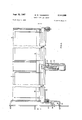
FIGURE 1 is a simplified front elevational view of the gate mechanism for a single vertical column of articles;
FIG. 2 is a fragmentary view, partly in section, of the lower end of a vending machine showing the gate mechanism and the lowering platforms for a single column of two vertical stacks of articles in tandem relation to be vended;
FIG. 3 is a fragmentary view similar to FIG. 2, but showing the lowering platform in the raised position and an article supported in vending position thereon during the first part of the vending cycle;
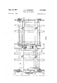
FIG. 4 is an enlarged side view, partly in section, showing details of the gate mechanism of the invention at the lower end of a vertical column of two stacks of articles to be vended;
FIG. 5 is a plan view taken on the line V-V of FIG. 4;
FIG. 6 is an enlarged sectional view taken on the line VI-VI of FIG. 5 showing the details of the alternator coupling mechanism together with the gate members and overlying shield members;
FIG. 7 is a view similar to FIG. 6, but showing the alternator mechanism in the position assumed as the gate members are being moved out to a vending position;
FIG. 8 is a view similar to FIG. 7, but shOWing the interengaging relation of the alternator members in the positions assumed just before the gate members are moved to their fully outer positions for releasing the lowermost article in a stack of articles; and
FIG. 9 is a view similar to FIGS. 6, 7 and 8 except showing the alternator mechanism and the gate and shield members in the positions assumed as they are returned to the article supporting relation beneath the next lowermost article in the vertical column as the lowermost article shown in FIG. 8 is released from the lowering platform and vended.
Referring now to FIGS. 1, 2 and 3 of the drawings, it should be understood that for purposes of simplifying the drawings and the description of the invention the mechanism for vending articles from only a single vertical storage column is shown, but that duplicate mechanisms may be provided under a plurality of side-by-side vertical storage columns in an arrangement similar to that shown in the previously mentioned US. Patent 3,118,567. Although as shown by FIGS. 2 and3 of the drawings only a single lifter plate 10 is described and a direct lever power connection including the lever member 11 is shown to be directly connected to the lifted plate 10, if a plurality of side-by-side vertical storage columns were used, a common lifting bar (not shown but similar to that of the above mentioned patent) would be provided to extend across the front of the vending machine and would be connected to lever 11 for vertical reciprocation. Such a lifter bar would be provided with individual selection solenoids for each side-by-side vertical column to connect a particular lifting plate, such as the lifting plate 10 for a particular vertical column with the common lifting bar at the time the lifting bar is raised and lowered to vend 3 an article from a selected one of the plurality of vertical storage columns.
For purposes of the present description the single lifting plate 10, as previously mentioned, is shown to be connected to the lever end 11 of the bell crank 12 which is pivotally mounted at 13 to an end wall of the machine. The ball crank 12 is pivotally connected at 14 to a reciprocating link 15 which is reciprocated by the movement of the connecting link 16 coupled to the crank 17 of a one revolution vend shaft or motor 18. It will be understood that for each vending operation the shaft or motor 18 is moved through a single revolution to reciprocate the connecting bar 15 and raise and lower the lifter plate 10 during a vending operation. Also, at the same time, lowering platform means which may comprise the crank arms 19 and 20 pivoted at 21 and 22 respectively, are raised to support any articles being vended during the vending operation and prevent cascading of either tandem stack of the entire vertical stored column of articles at the time that the gate mechanism, to be described, is opened to permit movement of an article such as shown at A in FIG. 3 of the drawing to a vending position as shown by FIG. 4 to be supported on the rods 23 and 24 of the lowering crank arm 20. It should be understood that a platform comprising a screen or similar sheet material (not shown) may be supported on the upper surface of the platform rods 23, 24 in a manner similar to that shown in the previously mentioned Patent 3,118,567 for preventing unauthorized access to the column stacks during vending. At the completion of the vend cycle the gate mechanism is moved back into position beneath the next lowermost articles in the columns of articles and the lowering platform arms 19 and 20 are again lowered to their position shown by FIG. 2 of the drawings allowing any articles previously supported thereon in vending position to be dropped down to a vending chute not shown.
Referring again to FIG. 1 of the drawings a pair of toggle links 25 and 26 are pivotally connected between the vertically movable lifter 10 and respective ends of the pivotal arms 27, 28. Gate members or bars 29 and extend from the other ends of the pivotal arms 27 and 28 respectively from front to back of the vending mamachine beneath the vertical column containing the two tandem stacks of articles to be vended. As more clearly shown by FIGS. 2 and 4 of the drawings the vertical column is deep enough to contain two tandem positioned stacks of articles to be vended with lowermost articles such as shown at A and B. These articles may be cylindrical articles such as cans or bottles although they may have other various shapes as may be suitable to be vended.
A pivotal shield member 31 is normally positioned to overlie the gate member or bar 29 beneath the lowermost article B in the rearward stack of tandem arranged stacks of articles. Similarly, a pivotal shield member 32 is normally positioned to overlie the other gate member 30 beneath the lowermost article A in the forward stack of articles in the vertical column of tandem stacked articles. The lifter plate or slide 10 is provided with a stop member 33 engaging a stationary frame member 34 of the machine to which the gate member pivotal arms 27 and 28 and the shield members 31 and 32 are pivotally attached. The stop member 33 on the slide lifter 10 serves to normally maintain the gate members or bars 29 and 30 together with their overlying shield members 31 and 32 in the article supporting position shown by FIG. 4 of the drawing. Alternator coupling means is provided within the housing at an intermediate position beneath the forward and rearward tandem stacks of articles to be vended. The details of the alternator coupling mechanism contained within the housing 40 are shown together with the mode of operation thereof by FIGS. 6-9 of the drawings and will now be described in detail.
Each shield member 31 and 32 is pivotally mounted at 41 and 42 respectively to the same respective pivot points for the gate member pivotal arms 27 and 28 which are located intermediate the length of the gate bars 29 and 30, more clearly shown by FIGS. 4 and 5 of the drawings. As will be clearly seen by FIGS. 4, 5 and 6 of the drawings the shield member 31 normally overlies the gate member rod 29 and engages in supporting relation the lowermost article B of the rear stack of articles while the shield member 32 normally overlies the gate member rod 30 and engages in supporting relation the lowermost article A in the front stack of articles to be vended. The alternator coupling member means includes a respective hook member 44 pivotally mounted at 45 on the shield member 31 and the hook member 46 pivotally mounted at 47 on the hook member 32. The hook member 44 is provided with a hook surface 47 adapted to be received in the hook recess 48 of the gate member or bar 29. Similarly, the hook member 46 is provided with a hook end 49 adapted to be received in the hook receiving recess 50 of the gate member or bar 30. Interengaging end surfaces 51 and 52 of the hook members 44, 46 engage each other respectively during each vending operation in a manner to alternately engage the hook end 47 with the gate bar 29 and the hook end 49 with the gate bar 30. Thus, in such manner each successive vending operation will alternately move either the shield 31 with the gate member 29 to vend article B or the shield member 32 with the gate member bar 30 to vend article A.
FIG. 6 of the drawings shows the alternator coupling mechanism in the positions assumed at the end of a vending operation in condition for a next subsequent vending operation that will be effective to vend article A from the forward stack of tandem arranged stacks of articles to be vended. It will be noted that the hook end 49 is received in the hook recess 50 of the gate bar 30 while the hook end 47 is disengaged from the gate bar 29. Thus, at the beginning of the vending operation being described, when the gate bars 29 and 30 move outwardly in the direction of the arrows shown by FIGS. 7 and 8 of the drawings the shield 32 will be moved together with the gate member 30 while the shield 31 will remain in its normal position in supporting relation beneath the article B in the rear stack of articles. Thus, article A is allowed to move downward as shown by FIGS. 7 and 8 of the drawings to the raised lowering platform as shown by FIG. 3 of the drawings. During the just described movement of the gate member bars 29 and 30 outwardly, the interengaging end surfaces 51 and 52 of the respective hook members 44 and 46 will assume first the position shown by FIG. 7 of the drawings and then the position shown by FIG. 8 of the drawings. At this time during the completion of the vending operation as the gate members or bars 29 and 30 move back in the direction of the arrows of FIG. 9 to article supporting position beneath the next lowermost article A in the forward column of articles to be vended, the interengaging end surfaces 50 and 52 cause the hook end 47 of the hook member 44 to engage the gate member bar 29 and the hook end surface 49 to disengage from the gate member bar 30. Thus at the end of the vending operation just being described, the shield member 31 is hooked to the gate bar 29 for movement therewith to vend article B during the next subsequent vending operation while the shield member 32 is disengaged from the gate member bar 30 to remain in normal position beneath the lowermost article A of the forward stack of articles. Each successive dispensing operation alternately couples first the shield member 31 for movement with the gate member 29 or the shield member 32 for movement with the gate member 30 so that each successive vending operation causes articles to be alternately vended from the front and back tandem arranged stacks of articles in the single vertical column of articles.
It should be understood that this invention in its broadest aspect is not limited to a particular alternator coupling mechanism since various arrangements for alternately connecting the respective overlying shield members 31 and 32 to the respective movable gate members 29 and 30 will be apparent to those skilled in the art. However, the arrangement of pivotal hook members having the interengaging end surfaces 51 and 52 is a presently preferred arrangement. Similarly it should be understood that the arrangement of lowering means to include the support rods such as the support rods 23, 24 and 23', 24' extending beneath the columns of articles is a generally diagrammatic arrangement and in actual practice detailed variations of lowering member structures may be provided. For example, a modified arrangement of the lowering mechanism as shown in the previously mentioned Patent 3,118,567 could be used in connection with a multiple column machine arranged to vend articles from two tandem stacks of articles in each column.
Various modifications will occur to those skilled in the art.
I claim as my invention:
1. In a dispensing mechanism for selectively releasing an article from the lower ends of a column of two tandem arranged vertical stacks of articles, the combination of a pair of gate members extending from front to rear beneath both of said stacks, means supporting said gate members for movement transversely of the article column towards and away from one another, a first shield member pivotally mounted to have a normal position overlying one of said gate members beneath one of said stacks, a second shield member pivotally mounted to have a normal position overlying of the other of said gate members beneath the other of said stacks, alternator coupling means interconnecting said shields and said gate members and repeatedly movable for alternately coupling the first shield member to the first gate member for movement therewith and the second shield member to the second gate member for movement therewith from their normal positions beneath said stacks of articles upon alternate successive vending movements of said gate members to alternately prevent and permit the release of an article from alternate ones of said two stacks, lowering means pivotally mounted beneath the gate members under respective stacks of articles and interconnected with said gate members to be movable from a normal article releasing lowered position to a raised article supporting position as said gate members are moved transversely from beneath the column of articles, and means for simultaneously moving said alternator coupling means and said gate member supporting means to thereby move said gate members towards and away from each other together with alternate ones of said shield members in alternate successive dispensing operations.
2. The invention of claim 1 in which said gate member supporting means includes pivotally mounted arms joined respectively to said gate members, and said means for moving said gate member supporting means includes a slide positioned between said arms and mounted for reciprocating movement in a plane normal to the pivotal axes of said arms, a pair of toggle links respectively connecting said slide to said arms, the pivotal axis of each arm being disposed intermediate the gate member and the connecting point with its associated link, the arrangement being such that upward movement of said slide is transmitted by said links to said arms to move said gate members away from one another, and downward movement of the slide is transmitted to said gate members to move said members toward one another, and a stop limiting downward movement of said slide, the connecting points between said links and said slide being positioned to pass through a line extending through the connecting points between said links and said arms as said slide is moved downwardly to said stop, said gate members being disposed a substantial distance from each other and above said pivotal axes when said slide is against said stop, whereby manual movement of said gate members upwardly and away from one another is prevented when said slide is against said stop.
3. The invention of claim 2 in which said alternator coupling means is comprised of a respective hook member pivotally mounted on a respective one of said shield members and movable between non-engaging and engaging positions, each of said hook members having a hook end for hooking together respective ones of said shield and gate members for simultaneous movement when the respective hook member is in the engaging position, each of said hook members further having interengaging end surfaces remote from their hook surfaces for alternately moving a respective one of each hook member from its non-engaging position to its engaging position whenever a respective other one of each hook and shield member is simultaneously moved with a respective one of said gate members.
4. The invention of claim 1 in which said alternator coupling means is comprised of a respective hook member pivotally mounted on a respective one of said shield members and movable between non-engaging and engaging positions, each of said hook members having a hook end for hooking together respective ones of said shield and gate members for simultaneous movement when the respective hook member is in the engaging position, each of said members further having interengaging end surfaces remote from their hook surfaces for alternately moving a respective one of each hook member from its nonengaging position to its engaging position whenever a respective other one of each hook and shield member is simultaneously moved with a respective one of said gate members.
References Cited UNITED STATES PATENTS 3,158,247 11/1964 Gale 221-116 X 3,209,942 10/ 1965 Gasparini et al. 221116 X ROBERT B. REEVES, Primary Examiner. STANLEY H. TOLLBERG, Examiner.
Dedication 3,341,069.Migs TV. Wei b62017, East Lnngmeadow, Mass. DOUBLE HOW CAN VENDOR. Patent dated Sept 12, 1967. Dedication filed Oct. 7, 1974, by the assignee, The Vanda Company. Hereby dedicates to the Public the entire remaining term of said patvnt.
[Ofiicz'al Gazette May 6', 1.975.]
Claims (1)
1. IN A DISPENSING MECHANISM FOR SELECTIVELY RELEASING AN ARTICLE FROM THE LOWER ENDS OF A COLUMN OF TWO TANDEM ARRANGED VERTICAL STACKS OF ARTICLES, THE COMBINATION OF A PAIR OF GATE MEMBERS EXTENDING FROM FRONT TO REAR BENEATH BOTH OF SAID STACKS, MEANS SUPPORTING SAID GATE MEMBERS FOR MOVEMENT TRANSVERSELY OF THE ARTICLE COLUMN TOWARDS AND AWAY FROM ONE ANOTHER, A FIRST SHIELD MEMBER PIVOTALLY MOUNTED TO HAVE A NORMAL POSITION OVERLYING ONE OF SAID GATE MEMBERS BENEATH ONE OF SAID STACKS, A SECOND SHIELD MEMBER PIVOTALLY MOUNTED TO HAVE A NORMAL POSITION OVERLYING OF THE OTHER OF SAID GATE MEMBERS BENEATH THE OTHER OF SAID STACKS, ALTERNATOR COUPLING MEANS INTERCONNECTING SAID SHIELDS AND SAID GATE MEMBERS AND REPEATEDLY MOVABLE FOR ALTERNATING COUPLING THE FIRST SHIELD MEMBER TO THE FIRST GATE MEMBER FOR MOVEMENT THEREWITH AND THE SECOND SHIELD MEMBER TO THE SECOND GATE MEMBER FOR MOVEMENT THEREWITH FROM THEIR NORMAL POSITIONS BE-
Priority Applications (1)
| Application Number | Priority Date | Filing Date | Title |
|---|---|---|---|
| US563767A US3341069A (en) | 1966-07-08 | 1966-07-08 | Double row can vendor |
Applications Claiming Priority (1)
| Application Number | Priority Date | Filing Date | Title |
|---|---|---|---|
| US563767A US3341069A (en) | 1966-07-08 | 1966-07-08 | Double row can vendor |
Publications (1)
| Publication Number | Publication Date |
|---|---|
| US3341069A true US3341069A (en) | 1967-09-12 |
Family
ID=24251821
Family Applications (1)
| Application Number | Title | Priority Date | Filing Date |
|---|---|---|---|
| US563767A Expired - Lifetime US3341069A (en) | 1966-07-08 | 1966-07-08 | Double row can vendor |
Country Status (1)
| Country | Link |
|---|---|
| US (1) | US3341069A (en) |
Cited By (3)
| Publication number | Priority date | Publication date | Assignee | Title |
|---|---|---|---|---|
| US3396869A (en) * | 1967-06-09 | 1968-08-13 | Norris Dispensers Inc | Dispensing apparatus with movable supply sources |
| US4460107A (en) * | 1982-02-08 | 1984-07-17 | Cavalier Corporation | Plural mode multi-column dispensing machine |
| US4509658A (en) * | 1984-01-11 | 1985-04-09 | Dixie-Narco, Inc. | Anti-theft device for tandem column vendor |
Citations (2)
| Publication number | Priority date | Publication date | Assignee | Title |
|---|---|---|---|---|
| US3158247A (en) * | 1961-04-28 | 1964-11-24 | Victor Products Corp | Dispensing machine for beverages in bottles or cans |
| US3209942A (en) * | 1962-02-14 | 1965-10-05 | Westinghouse Electric Corp | Article dispensing mechanism |
-
1966
- 1966-07-08 US US563767A patent/US3341069A/en not_active Expired - Lifetime
Patent Citations (2)
| Publication number | Priority date | Publication date | Assignee | Title |
|---|---|---|---|---|
| US3158247A (en) * | 1961-04-28 | 1964-11-24 | Victor Products Corp | Dispensing machine for beverages in bottles or cans |
| US3209942A (en) * | 1962-02-14 | 1965-10-05 | Westinghouse Electric Corp | Article dispensing mechanism |
Cited By (3)
| Publication number | Priority date | Publication date | Assignee | Title |
|---|---|---|---|---|
| US3396869A (en) * | 1967-06-09 | 1968-08-13 | Norris Dispensers Inc | Dispensing apparatus with movable supply sources |
| US4460107A (en) * | 1982-02-08 | 1984-07-17 | Cavalier Corporation | Plural mode multi-column dispensing machine |
| US4509658A (en) * | 1984-01-11 | 1985-04-09 | Dixie-Narco, Inc. | Anti-theft device for tandem column vendor |
Similar Documents
| Publication | Publication Date | Title |
|---|---|---|
| US3001669A (en) | Vending and dispensing device | |
| US3160292A (en) | Shopping cart stacker | |
| US3991907A (en) | Solid merchandise dispensing system for mechanical or electrical control | |
| US3341069A (en) | Double row can vendor | |
| GB1162160A (en) | Merchandise Vending Machine | |
| US3419186A (en) | Article dispenser | |
| US3209942A (en) | Article dispensing mechanism | |
| GB1220295A (en) | Improvements in or relating to vending machines | |
| US3224631A (en) | Dispensing mechanism for articles in front to back staggered stacks | |
| US2726749A (en) | Coin controlled mechanism for vending machines | |
| US3756362A (en) | Vending machine having sequential actuation of disperser | |
| US3379342A (en) | Multiple column vending machine | |
| US3189217A (en) | Food dispensing apparatus | |
| US2543687A (en) | Vending machine | |
| US2008926A (en) | Coin controlled vending machine | |
| US3169621A (en) | Selective bottle vending machine | |
| US3322303A (en) | Release mechanism for vending machines | |
| US3107812A (en) | Dispensing mechanism for articles in staggered stack | |
| US3347413A (en) | Article dispenser with automatic replacement of depleted stack with a similar stack | |
| US3312512A (en) | Vending machine article delivery chute arrangement | |
| US3299613A (en) | Carton carrier | |
| US2376562A (en) | Dispensing machine | |
| US3319821A (en) | Plural source article dispenser with separate discharge means for each source | |
| US3095115A (en) | Delivery mechanism for vending machines | |
| US2227663A (en) | Coin controlled mechanism for vending machines |