US3338415A - Sewage treatment system - Google Patents
Sewage treatment system Download PDFInfo
- Publication number
- US3338415A US3338415A US43336165A US3338415A US 3338415 A US3338415 A US 3338415A US 43336165 A US43336165 A US 43336165A US 3338415 A US3338415 A US 3338415A
- Authority
- US
- United States
- Prior art keywords
- tank
- sections
- aeration
- air
- sewage
- Prior art date
- Legal status (The legal status is an assumption and is not a legal conclusion. Google has not performed a legal analysis and makes no representation as to the accuracy of the status listed.)
- Expired - Lifetime
Links
- 239000010865 sewage Substances 0.000 title claims description 41
- 238000011282 treatment Methods 0.000 title claims description 17
- 238000005273 aeration Methods 0.000 claims description 36
- 239000007787 solid Substances 0.000 description 10
- XLYOFNOQVPJJNP-UHFFFAOYSA-N water Substances O XLYOFNOQVPJJNP-UHFFFAOYSA-N 0.000 description 6
- 239000007788 liquid Substances 0.000 description 5
- 230000000630 rising effect Effects 0.000 description 3
- 239000010802 sludge Substances 0.000 description 3
- 229910000831 Steel Inorganic materials 0.000 description 2
- 230000015572 biosynthetic process Effects 0.000 description 2
- 230000008878 coupling Effects 0.000 description 2
- 238000010168 coupling process Methods 0.000 description 2
- 238000005859 coupling reaction Methods 0.000 description 2
- 230000029087 digestion Effects 0.000 description 2
- 238000000034 method Methods 0.000 description 2
- 239000010959 steel Substances 0.000 description 2
- 238000003786 synthesis reaction Methods 0.000 description 2
- 238000003466 welding Methods 0.000 description 2
- 230000004308 accommodation Effects 0.000 description 1
- 230000000712 assembly Effects 0.000 description 1
- 238000000429 assembly Methods 0.000 description 1
- 238000010276 construction Methods 0.000 description 1
- 235000012489 doughnuts Nutrition 0.000 description 1
- 210000002310 elbow joint Anatomy 0.000 description 1
- 238000012423 maintenance Methods 0.000 description 1
- 230000004048 modification Effects 0.000 description 1
- 238000012986 modification Methods 0.000 description 1
- 230000008520 organization Effects 0.000 description 1
- 230000002093 peripheral effect Effects 0.000 description 1
- 229920001084 poly(chloroprene) Polymers 0.000 description 1
- 125000006850 spacer group Chemical class 0.000 description 1
Images
Classifications
-
- C—CHEMISTRY; METALLURGY
- C02—TREATMENT OF WATER, WASTE WATER, SEWAGE, OR SLUDGE
- C02F—TREATMENT OF WATER, WASTE WATER, SEWAGE, OR SLUDGE
- C02F3/00—Biological treatment of water, waste water, or sewage
- C02F3/02—Aerobic processes
- C02F3/12—Activated sludge processes
-
- Y—GENERAL TAGGING OF NEW TECHNOLOGICAL DEVELOPMENTS; GENERAL TAGGING OF CROSS-SECTIONAL TECHNOLOGIES SPANNING OVER SEVERAL SECTIONS OF THE IPC; TECHNICAL SUBJECTS COVERED BY FORMER USPC CROSS-REFERENCE ART COLLECTIONS [XRACs] AND DIGESTS
- Y02—TECHNOLOGIES OR APPLICATIONS FOR MITIGATION OR ADAPTATION AGAINST CLIMATE CHANGE
- Y02W—CLIMATE CHANGE MITIGATION TECHNOLOGIES RELATED TO WASTEWATER TREATMENT OR WASTE MANAGEMENT
- Y02W10/00—Technologies for wastewater treatment
- Y02W10/10—Biological treatment of water, waste water, or sewage
Definitions
- aeration tanks for the synthesis and aerobic digestion of solids in the solid laden liquid sewage.
- the aeration tanks are normall specially designed and constructed with extensive aeration and sewage mixing baflle equipment self-contained. Such tanks are, as might be expected, relatively complicated and expensive.
- a sewage treatment aeration and mixing system comprising .a series of identical prefabricated sections which are assembled like building blocks in a conventional water tight storage tank, of any size and configuration.
- the identical sewage mixing and aeration sections are assembled and interconnected along the upper inner periphery of a storage tank and have air transfer, air diffuser, and sewage turning characteristics which, acting in concert, provide the system with a complete aeration and mixing program for the sewage introduced to the tank.
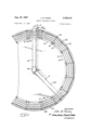
- FIGURE 1 is a plan View, with parts broken away, of a conventional water tight storage tank modified with an aeration and mixing system embodying features of the present invention to make an aeration tank for sewage treatment;
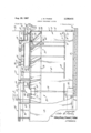
- FIGURE 2 is a sectional view taken along line 22 of FIGURE 1, with parts broken away.
- the tank 11 is a conventional circular cylindrical steel tank comprising a continuous wall 12 and a floor 13 mounted on a concrete base 14. Assembly of the mixing and aeration system 10 on the upper periphery of the wall 12, with the addition of a suitable sewage and activated sludge introduction and rem-oval system to the tank 11 transforms the tank into a complete sewage treatment aeration tank.
- the system 10 embodying features of the present invention comprises a series of mixing and aeration sections interconnected to form the complete system; the number of sections being deter-mined solely by the diameter of the tank 11 (in cases where the tank is cylindrical). Since the mixing and aeration sections 25 are substantially identical, only one will be described in detail here. Corresponding components of the remaining sections 25 are given corresponding reference numerals.
- Each mixing and aeration section 25 includes a combination turning baflle and support assembly 26 mounted on the upper periphery of the wall 12, an air header and diffuser assembly 27 mounted on the support assembly 26, and a walkway assembly 28 mounted on the support assembly 26.
- the air header and diffuser assembly 27 transmits air and emits it in the tank 11 to aerate the solid laden liquid sewage therein and cause it to circulate upwardly toward the baflle and support assembly 26 which turns the sewage inwardly to establish a desirable rotational flow.
- the walkway-assembly 28 provides access to the entire system 10 for maintenance personnel.
- the baffle and support assembly 26 includes a pair of vertically extending steel straps 30 braced against the inner surface of the tank wall 12 in circumferentially spaced relationship.
- the straps 30 have outwardly extending upper lips 32 which overlie the peripheral upper rim 33 formed on the tank 12 and arebolted thereto.
- An angle member 35 is secured to the upper end of each strap by welding or the like, as at 36, and extends in cantilever relationship radially inwardly of the tank wall 12.
- the innermost end 37 of each angle member 35 and the lowermost end 38 of each vertical strap 30 are joined to a sewage baffle plate 40.
- the plate 40 is inclined inward ly from the tank wall 12 at a angle.
- the turning baflle plate 40 is generally trapezoidal in shape.
- a flange 44 is bent inwardly from the plane of the plate 40 to define its lower edge and stiffen the plate in a horizontal plane.
- Another flange 45 is bent upwardly from the plane of the plate 40 to define its upper edge and also provide horizontal stiffening.
- the inner ends 37 of the angle members 35 are welded to the flange 45.
- Flanges 49 are bent inwardly from the plate 40 to define the edges of the plate and provide vertical stiffening.
- the plate 40, with its stiffening flanges 44, 45, and 49 thus defines a rigid sewage turning baflie and support assembly 26 with the pair of angle members 35 and the straps 30.
- This rigid assembly 26 provides a structural support for the walkway assembly 28 and the air header and diffuser assembly 27.
- the air header and diffuser assembly includes a vertical-1y disposed support post 50 welded to each end of the stiffening flange 45 and a corresponding angle member 35 and extending upwardly therefrom. Opposite ends of the air header pipe section 53 are secured to the inner sides of corresponding support posts 50 by conventional U-clamps 54. The header pipe section 53 is thus disposed over and slightly inwardly of the flange 45.
- the pipe section 53 has an air diffuser drop pipe connected to and depending therefrom at a central T-joint 61.
- a manually controlled valve 62 of conventional construction is interposed in the pipe 60 adjacent the joint 61 for controlling the flow of air from the pipe section 53 through the pipe 60 to an air diffuser unit 64.
- the air diffuser unit 64 comprises an elongated horizontal manifold pipe capped at both ends and connected to the lower end of the drop pipe 60 by a short pipe 71 and an elbow joint 72.
- the pipe 71 extends radially outwardly from the joint 72 so that the manifold pipe 70 is approximately centered under the battle plate 40.
- the manifold pipe 70 has a plurality of spaced, ditfuser elements 75 extending perpendicularly from opposite sides thereof, in a horizontal plane.
- Each of the diffuser elements 75 is a short pipe section capped at its outer end 76 and having a plurality of air outlet ports 77 formed in each side.
- the walkway assembly 28 for each aeration section 25 includes three planks 80, 81, and 82 which overlie the angle members 35 of the sewage turning battle and support assembly 27 and are secured thereto by any suitable means (not shown).
- the planks 8082 are of increasing length from the inside plank 80 to the outside plank 82 and their opposite ends are cut so each plank is substantially trapezoidal in shape to accommodate adjacent aeration sections 25 in the circular cylindrical tank 11.
- the walkway assembly further includes an outer handrail 85 mounted on the radially extending lips 36 of mounting straps 34.
- the handrail 85 is generally U-shaped (inverted) and a cross brace 86 interconnects its vertical legs 87. The lower ends of the legs 87 are secured to the lips 36 by welding or the like.
- the air header section 53 acts as an inner handrail.
- Each of the aeration sections 25 which has been described to this point is a completely self-contained unit.
- the sections 25, when mounted in immediately adjacent relationship on the wall 12 of the tank 11, as illustrated, are unconnected to each other except for the air header sections 53 which must, of course, be interconnected to provide a common conduit for air directed to the diffuser units 64.
- the air header sections 53 are interconnected by flexible, sleeve-type neoprene couplings 90 secured to corresponding adjacent ends 51 and 52 of the header sections by conventional ring clamps 91.
- Air is introduced to the interconnected series of header sections 53 through an L-shaped inlet conduit 95.
- the upstanding leg 96 of the inlet conduit 95 is connected in air tight relationship to one of the header sections 53 while the horizontal leg 97 extends outwardly over the walkway planks 8082 of a corresponding walkway assembly 28.
- the open free end 98 of the inlet conduit 95 is adapted to be connected to any suitable source of air under pressure (not shown).
- a horizontally extending sewage inlet pipe 105 also overlies the walkway planks 80-82 of the walkway assembly 28 with which the air inlet conduit 95 is associated.
- the pipe 105 terminates at .a centrally disposed elbow having a downwardly directed outlet 106a positioned directly above a splash plate 107.
- the splash plate 107 and the inner end of the pipe 105, through the elbow 106, are supported by a central support column 110 extending upwardly through the floor of the tank 11 from the concrete base thereof.
- the splash plate 107 is spaced from and supports the elbow 106 on a peripherally arranged series of spacer rods 111.
- a stile is constructed on the walkway assembly in question.
- the stile comprises lower steps 116 formed of short plank sections suitably supported from the planks 8082 on opposite sides of the sewage inlet pipe 105, and a top step 117 formed of slightly longer plank sections supported from the planks 8082 in the same manner and extending over the sewage inlet pipe 105.
- a modified handrail 120 conforming generally to the configuration of the stile is utilized in lieu of the handrail 85 hereinbefore described.
- the lowest steps 116 on one side of the stile overlie the air inlet conduit 95.
- the rising air bubbles cause the sewage to circulate in what approximates a doughnut shaped path upwardly against the turning baffle plates 40 and inwardly toward the center of the tank 11, whereupon the sewage moves down toward the tank floor and outwardly toward the air diffuser units 64 once more.
- the aerated sewage is removed from the tank 11 to suitable sewage handling equipment for transfer of the sewage to a clarifier stage of the sewage treatment, for example.
- the aeration cycle ordinarily ranges from in the neighborhood of one hour for an initial or synthesis stage aeration to four hours for aerobic digestion stage aeration.
- the aeration and mixing system which has been described facilitates inexpensively modifying a standard liquid storage tank for use as a sewage treatment aeration tank.
- Any number of the aeration and mixing sections 25 can be joined together by air header couplings to construct a system 10 for any size tank 11.
- the sections 25 are not interconnected in any other way, for ease of system assembly; and, in fact, are connected to the tank 11 only by the strap lips 32 bolted to the tank rim 33. Virtually no modification of a standard storage tank is thus necessary.
- the system 10 is designed to prevent stagnation in the tank 11 by assuring some air up flow up behind the baffle plates 40. A certain portion of the rising air bubbles pass behind the lower stifiening flanges 44 of the plates 40 because the air diffuser units 64 are spaced a substantial distance below the plates. The gaps between baflie plates 40 permit circulation of floating solids from behind the plates.
- An aeration and mixing system for converting a conventional liquid-tight storage tank having an upstanding side wall 'into a sewage treatment tank, comp-rising: a plurality of substantially identical aeration and mixing sections, means for mounting said sections in end-to-end relationship on and around the upper periphery of the tank wall, each of said sections including vertically extending member means adapted to be braced against the inside of the wall, horizontal support means attached to said member means and extending inwardly of the wall, and turning baffle means mounted on said vertically extending member means and inclined inwardly of the tank into supporting relationship with the inner ends of said support means, said baflle means in each section extending into generally edge-to-edge adjacent relationship, walkway means and air transfer pipe section means mounted on said support means in each section, conduit means interconnecting said pipe sections, air diffuser means depending below said bafaerate the sewage in the tank and induce its flow in the tank upwardly against said balfie means and inwardly of the tank.
- the system of claim 1 further characterized in that the storage tank has a generally circular cylindrical side wall and said aeration and mixing sections are arranged around said side wall in adjacent end-to-en-d relationship.
- each of said bafiie means comprises a generally trapezoidal shaped plate member having its longest edge positioned against the tank side wall and a bafile surface inclined away firom the wall.
- said vertically extending member means comprises strap members having outwardly disposed hook means formed at their upper ends and overlying the upper periphery of the tank wall.
Landscapes
- Life Sciences & Earth Sciences (AREA)
- Biodiversity & Conservation Biology (AREA)
- Microbiology (AREA)
- Hydrology & Water Resources (AREA)
- Engineering & Computer Science (AREA)
- Environmental & Geological Engineering (AREA)
- Water Supply & Treatment (AREA)
- Chemical & Material Sciences (AREA)
- Organic Chemistry (AREA)
- Treatment Of Biological Wastes In General (AREA)
- Aeration Devices For Treatment Of Activated Polluted Sludge (AREA)
Priority Applications (3)
| Application Number | Priority Date | Filing Date | Title |
|---|---|---|---|
| US43336165 US3338415A (en) | 1965-02-17 | 1965-02-17 | Sewage treatment system |
| GB350066A GB1138481A (en) | 1965-02-17 | 1966-01-26 | Sewage treatment system |
| BE676363D BE676363A (enExample) | 1965-02-17 | 1966-02-11 |
Applications Claiming Priority (1)
| Application Number | Priority Date | Filing Date | Title |
|---|---|---|---|
| US43336165 US3338415A (en) | 1965-02-17 | 1965-02-17 | Sewage treatment system |
Publications (1)
| Publication Number | Publication Date |
|---|---|
| US3338415A true US3338415A (en) | 1967-08-29 |
Family
ID=23719888
Family Applications (1)
| Application Number | Title | Priority Date | Filing Date |
|---|---|---|---|
| US43336165 Expired - Lifetime US3338415A (en) | 1965-02-17 | 1965-02-17 | Sewage treatment system |
Country Status (3)
| Country | Link |
|---|---|
| US (1) | US3338415A (enExample) |
| BE (1) | BE676363A (enExample) |
| GB (1) | GB1138481A (enExample) |
Cited By (2)
| Publication number | Priority date | Publication date | Assignee | Title |
|---|---|---|---|---|
| US3680847A (en) * | 1970-08-31 | 1972-08-01 | Standard Oil Co | Method of and apparatus for aerating water |
| US4181614A (en) * | 1976-06-17 | 1980-01-01 | The British Petroleum Company Limited | Sludge removal apparatus |
Citations (10)
| Publication number | Priority date | Publication date | Assignee | Title |
|---|---|---|---|---|
| US1286775A (en) * | 1916-10-06 | 1918-12-03 | Pacific Flush Tank Co | Device for activating sludge. |
| US2126228A (en) * | 1936-08-27 | 1938-08-09 | Municipal Sanitary Service Cor | Activated sludge purification of sewage and other liquids |
| US2407947A (en) * | 1945-06-19 | 1946-09-17 | Gulf Oil Corp | Apparatus for the clarification of liquids |
| GB651167A (en) * | 1948-07-26 | 1951-03-14 | Activated Sludge Ltd | Improvements in and relating to the aeration treatment of sewage |
| US2624657A (en) * | 1947-03-12 | 1953-01-06 | American Metal Co Ltd | Submerged blast reaction tank |
| US3028011A (en) * | 1960-09-14 | 1962-04-03 | Robert F Mcgivern | Aerobic digestion system for use in sewage treatment |
| GB925993A (en) * | 1959-01-19 | 1963-05-15 | Kloeckner Humboldt Deutz Ag | A clarifying apparatus for liquids which contain finely divided solids |
| US3195727A (en) * | 1961-09-18 | 1965-07-20 | Union Tank Car Co | Waste products treatment apparatus having floating solid feedback structure |
| US3220706A (en) * | 1963-06-07 | 1965-11-30 | Pacific Flush Tank Co | Sewage treatment system |
| US3233922A (en) * | 1963-07-29 | 1966-02-08 | Cast Iron Soil Pipe Inst | Pipe joint |
-
1965
- 1965-02-17 US US43336165 patent/US3338415A/en not_active Expired - Lifetime
-
1966
- 1966-01-26 GB GB350066A patent/GB1138481A/en not_active Expired
- 1966-02-11 BE BE676363D patent/BE676363A/xx unknown
Patent Citations (10)
| Publication number | Priority date | Publication date | Assignee | Title |
|---|---|---|---|---|
| US1286775A (en) * | 1916-10-06 | 1918-12-03 | Pacific Flush Tank Co | Device for activating sludge. |
| US2126228A (en) * | 1936-08-27 | 1938-08-09 | Municipal Sanitary Service Cor | Activated sludge purification of sewage and other liquids |
| US2407947A (en) * | 1945-06-19 | 1946-09-17 | Gulf Oil Corp | Apparatus for the clarification of liquids |
| US2624657A (en) * | 1947-03-12 | 1953-01-06 | American Metal Co Ltd | Submerged blast reaction tank |
| GB651167A (en) * | 1948-07-26 | 1951-03-14 | Activated Sludge Ltd | Improvements in and relating to the aeration treatment of sewage |
| GB925993A (en) * | 1959-01-19 | 1963-05-15 | Kloeckner Humboldt Deutz Ag | A clarifying apparatus for liquids which contain finely divided solids |
| US3028011A (en) * | 1960-09-14 | 1962-04-03 | Robert F Mcgivern | Aerobic digestion system for use in sewage treatment |
| US3195727A (en) * | 1961-09-18 | 1965-07-20 | Union Tank Car Co | Waste products treatment apparatus having floating solid feedback structure |
| US3220706A (en) * | 1963-06-07 | 1965-11-30 | Pacific Flush Tank Co | Sewage treatment system |
| US3233922A (en) * | 1963-07-29 | 1966-02-08 | Cast Iron Soil Pipe Inst | Pipe joint |
Cited By (2)
| Publication number | Priority date | Publication date | Assignee | Title |
|---|---|---|---|---|
| US3680847A (en) * | 1970-08-31 | 1972-08-01 | Standard Oil Co | Method of and apparatus for aerating water |
| US4181614A (en) * | 1976-06-17 | 1980-01-01 | The British Petroleum Company Limited | Sludge removal apparatus |
Also Published As
| Publication number | Publication date |
|---|---|
| BE676363A (enExample) | 1966-06-16 |
| GB1138481A (en) | 1969-01-01 |
Similar Documents
| Publication | Publication Date | Title |
|---|---|---|
| US3741393A (en) | Aeration septic tank | |
| US4325823A (en) | Wastewater treatment system | |
| US3907672A (en) | Aerobic sewage digestion system | |
| US4139471A (en) | Sewage treatment unit | |
| US3975276A (en) | Modular aerator and separator assembly for sewage treatment facility | |
| US3339901A (en) | Aeration equipment with easy-raising facilities | |
| US3767051A (en) | Sewage treatment vessel | |
| US5162083A (en) | Individual home wastewater treatment plant conversion apparatus | |
| US3338415A (en) | Sewage treatment system | |
| US3438499A (en) | Vessel for aerobic digestion sewage treatment plant | |
| US3859215A (en) | Sewage treatment system | |
| US3397789A (en) | Sewage treatment system | |
| US1979272A (en) | Pontoon floating deck for tanks | |
| US3528549A (en) | Apparatus for the treatment of waste water | |
| US2024986A (en) | Apparatus for and method of sewage treatment | |
| AU2017221394A1 (en) | Foldable and removable partition assembly for septic tank | |
| US3434598A (en) | Apparatus for treating sewage or industrial waste liquids | |
| US4081167A (en) | Vertically flaring concrete form | |
| US3876541A (en) | Packed bed reactor apparatus for wastewater treatment | |
| US3239067A (en) | Combined clarifier and digester of high capacity | |
| US5271832A (en) | Activation plant with funnel-shaped secondary sedimentation | |
| NO131780B (enExample) | ||
| US3595396A (en) | Arrangement for water treatment | |
| AU665241B2 (en) | Secondary sewage treatment system | |
| US3028967A (en) | Apparatus for the treatment of sanitary sewage |
Legal Events
| Date | Code | Title | Description |
|---|---|---|---|
| AS | Assignment |
Owner name: SMITH & LOVERLESS, INC., A CORP. OF KS. Free format text: ASSIGNMENT OF ASSIGNORS INTEREST.;ASSIGNOR:ECODYNE CORPORATION;REEL/FRAME:003924/0764 Effective date: 19811008 |