US3338403A - Package of aerosol cans, carton and carton blank therefor - Google Patents
Package of aerosol cans, carton and carton blank therefor Download PDFInfo
- Publication number
- US3338403A US3338403A US440133A US44013365A US3338403A US 3338403 A US3338403 A US 3338403A US 440133 A US440133 A US 440133A US 44013365 A US44013365 A US 44013365A US 3338403 A US3338403 A US 3338403A
- Authority
- US
- United States
- Prior art keywords
- carton
- cans
- forming
- flap
- package
- Prior art date
- Legal status (The legal status is an assumption and is not a legal conclusion. Google has not performed a legal analysis and makes no representation as to the accuracy of the status listed.)
- Expired - Lifetime
Links
Images


Classifications
-
- B—PERFORMING OPERATIONS; TRANSPORTING
- B65—CONVEYING; PACKING; STORING; HANDLING THIN OR FILAMENTARY MATERIAL
- B65D—CONTAINERS FOR STORAGE OR TRANSPORT OF ARTICLES OR MATERIALS, e.g. BAGS, BARRELS, BOTTLES, BOXES, CANS, CARTONS, CRATES, DRUMS, JARS, TANKS, HOPPERS, FORWARDING CONTAINERS; ACCESSORIES, CLOSURES, OR FITTINGS THEREFOR; PACKAGING ELEMENTS; PACKAGES
- B65D5/00—Rigid or semi-rigid containers of polygonal cross-section, e.g. boxes, cartons or trays, formed by folding or erecting one or more blanks made of paper
- B65D5/42—Details of containers or of foldable or erectable container blanks
Definitions
- This invention relates to a package of aerosol cans and to a carton and to a carton blank for use in making such a package.
- a mixing of the contents of two cans can be accomplished by the use of suitably designed valve-controlled dispensing mechanisms, so arranged and constructed that when the dispensing ends of the aerosol cans are placed in properly aligned relationship for the cooperative action of the.respective valve mechanisms and the cans forced together, the contents of the more highly pressurized can will be discharged into the other can for admixture with the contents thereof.
- the reaction mixture therein is ready to' be discharged at whatever site is chosen for the build-up of the foamed resin.
- Such a two-can system being readily portable, facilitates the delivery of the resin-forming mixture wherever the foamed resin is needed for insulation or other purposes.
- the carton of my present invention is designed to contain two aerosol cans such as described and to facilitate the mixing of the contents of the two cans while in the resulting package.
- the packaging arrangement is such that it is impossible for the contents of the cans to be mixed inadvertently while in storage or at any time before intentional use of the package. Additionally, in order to reduce any hazard during the mixing of the contents of the two cans, the carton is provided with means for locking the carton closed until the mixing of the contents of the two cans has been completed.
- the carton of my invention is formed from a onepiece blank of sheet-like material, such as fiberboard or the like, which is so formed and arranged with score lines, or the lines of weakness, slits and interlocking tabs, as to be readily foldable to erect the blank into the form of a carton having the special features adapting it for the two-can aerosol system just described.
- These special features include a cut-out portion in one of the side panels of the carton that forms an opening, a door forming flap for such opening, and a spacing member that is adapted to be inserted through said opening to be between the packaged aerosol cans and thereby prevent premature actuation of their dispensing valves.
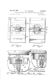
- FIG. 1 is a perspective, elevational view of a package of a pair of aerosol cans wherein the carton and the resulting package embody the principles of my invention
- FIG. 2 is a top plan view of a one-piece blank suitable for making the carton of FIG. 1;
- FIG. 3 is a perspective plan view of a spacer member forming a part of the package of FIG. 1;
- FIG. 4 is an enlarged vertical sectional view taken substantially along the line IVIV of FIG. 1, showing the pair of aerosol cans in elevation and illustrating the positioning of the spacer member of FIG. 3 to prevent interaction between the valve mechanisms of the two cans;
- FIG. 5 is a fragmentary elevational View during the stage at which the opening for the insertion of the spacer member into the package, or for its removal from the package, lies uncovered by the door-forming flap provided for the purpose;
- FIG. 6 is an enlarged fragmentary elevational view similar to FIG. 5, but with the spacer member removed;
- FIG. 7 is a view similar to FIG. 6 after endwise collapsing of the carton and the interengagement of the dispensing mechanisms of the two aerosol can-s during the act of transferring the contents from one can to the other;
- FIG. 8 is a further enlarged, fragmentary elevational view, partially broken away and in section, illustrating the position of the dispensing portions of the two cans in an engaging but inactive relationship;
- FIG. 9 is a view similar to- FIG. 8, but with the dispensing portions of the two cans in active, cooperative relationship for effecting the transfer of the contents of one can into the other;
- FIG. is a sectional view of the valve dispensing mechanism of the upper of the two cans after disengagement from the lower can.
- the reference numeral 10 indicates generally a package embodying the principles of my invention.
- Said pack-age includes a carton generally represented by the reference numeral 11 and a pair of aerosol cans 12 and 13, which, as best shown in FIG. 4, are contained within the carton 11 endwise relationship with the annular reduced ends [4 and 15, respectively, opposed to one another. If it be assumed that the package is shown in its upright position, as in FIG. 1, the lower can 13 is upright and the upper can 12 is inverted with a spacer member 16, tobe described later, separating the reduced ends 14 and 15 of the respective cans.
- a carton-forming blank indicated as a whole by the reference numeral 17 comprises a one-piece flat sheet of material that has been die-cut or otherwise formed, and provided with slits and lines of fold, score lines and the like, positioned and arranged as required for the erection of the blank into the form of the carton 11.
- lines of weakness may refer to score lines or to other lines along which a folding is to take place or where there is to be a complete removal of a portion of the carton wall, as in the case of a cut-out.
- the blank 17 comprises four elongated, sidewall forming panels 18, 19, 20 and 21, all of which are rectangular in shape and of substantially the same dimensions, since the preferred form of carton is one that has a square cross-section only slightly larger in size than the size required for accommodation of the cans 12 and 13.
- the panels 18, 19, 20 and 21 are joined respectively to lines of fold 22, 23 and 24, extending the full distance between transverse lines of fold and 26, except for slits provided in the lines of fold that will be described later.
- the lines of fold 22, 23 and 24 are sometimes referred to as edge-forming lines of fold.
- a pair of spaced joint-forming flaps 29 and 30 extend beyond the line of fold 27.
- said flaps 29 and 30 are adhesively secured inwardly of the free edge 28 to the underside of the panel 21 as viewed in FIG. 2.
- An adhesive, indicated at 31 may be applied to the upper sides of the joint-forming flaps 29 and 30 and the joint formed by heat, or heat and pressure, between said flaps and the back face of the panel 21, or any conventional method of forming the joint may be employed.
- a door-forming flap 32 extends from a line of fold 33 that is substantially in alignment with the free edge 28 of the panel 21 and is intermediate the end edge lines of fold 25 and 26.
- Said door-forming flap 32 has a pair of spaced tabs 34 and 35 extending from the ends of the free edge 36 of said flap 32 and foldaole about lines of fold 37 and 38.
- Said door-forming flap 32 functions to close an opening 65 (later to be described more fully) formed by removing a knock-out portion 39 formed by arcuate lines of curvature 40 and 41 in the panel 18 and extending substantially completely thereacross along a median line of said panel 18.
- a plurality of score lines 42, 43 and 44 extend in parallel spaced relationship across the panels 19, 2t) and 21 and spanning the width of the door-forming fiap 32 all the way across from the line of fold 22 to the free edge 36 of said line of said flap.
- These lines of fold 42, 43 and 44 may be score lines or lines of weakness, the purpose of which will later appear, but it is suflicient here to note that the hand between the score lines 42 and 44 form, in general, a continuation of the knock-out portion 39 and lies within the maximum extent of the lines of weakness 40 and 41 defining said knock-out portion 39.
- a plurality of end closure-forming fl-aps 45, 46, 47 and 48 extend beyond the line of fold 25 joining said extensions, respectively, with one end of each of the panels 18, 19, 20 and 21. Similar end closure-forming flaps 45a, 46a, 47a and 48a extend beyond the line of fold 26 that joins them with the corresponding panels 18, 19, 20 and 21 respectively.
- the flaps 45 and 45a are identically formed and are provided with integral tabs 49 and 49a that are foldable about score lines 50 and 50a.
- a pair of spaced angled slits 51 and 52 intersect the end edgeforming line of fold 25 between the flap 45 and the panel 18 and a similar pair of slits 51a and 52a intersect the line of fold 26.
- Said slits 51 and 52 and 51a and 52a are joinedrespect-ively, by slits 53 and 53a formed in the lines of folds 25 and 26, respectively.
- the end closure tabs 47 and 47a are provided at their ends with looking tabs 54 and 54a having re-entrant slits 55, 56 and 55a, 56a inwardly of the divergent arcuate edges 57, 58, and 57a, 58a of said tabs 54 and 54a.
- the locking tabs 54 and 54a are adapted to be inserted into the openings provided by the slits 53 and 53a and locked therein to lock the carton closed.
- Each of the end closure-forming flaps 46 and 46a is of generally rectangular shape and extends free of the adjoining tabs 45, 47 and 45a and 47a, by virtue of narrow slits 59 and 59a between the flaps 45, 46 and 45a, 46a, and by virtue of wider spaces 60 and 60a between the flaps 46, 4'7 and 46a, 47a, respectively.
- the adjacent edges of the flaps 46 and 46a are relieved to provide these wider spaces 60 and 60a, so as to prevent interference when setting up the carton.
- the flaps 48 and 48a are provided with wider spaces 61 and 61a between adjacent edgesof the flaps 47, 48 and 47a, 48a, respectively.
- Slits 63 and 64 are formed in substantial alignment with the edge-forming line of fold 22 in spaced relation from one another to receive, when the carton is erected, the tabs 34 and 35 on the door-forming flap 32.
- the flap 32 In swinging the door-forming flap 32 about the line of fold 33 to close the opening 65 provided by the knock-out portion 39, the flap 32 is moved into position overlying said panel 18 and to hold it in that position the tabs 34 and 35 are inserted into the slots 63 and 64, respectively, to be engaged therein.
- the aero sol can 13 is first inserted into the carton to bottom against the closed lower end that is closed by the flaps 45a, 46a, 47 and 48a.
- the cam 13 fits snugly therein at the bottom against the upturned flaps 54a and 49a.
- the spacer member 16 is then inserted through the opening 65 so provided for the insertion and removal of said spacer member 16.
- the spacer member 16 comprises a square of double-faced corrugated board 66 having a slot 67 extending inwardly from one edge thereof to a central circular opening 68. The function of this slot and opening will be apparent as the description proceeds.
- the upper can 12 is inserted into the carton in an inverted position.
- a downwardly and axially extending tube 69 forming a part of the dispensing and valved mechanism of the can 12 becomes. automatically aligned with an opening 70 (FIG. 6) in a conventional closure forming a part of the can 13.
- the tube 69 extends through the central opening 68 of th Spacer member.
- Said spacer member 16 is of such thick ne'ss that the beaded bottom 70 of the upper can 12 abuts the inside of the upper closed end of the carton formed by the end flaps 45, 46, 47 and 48.
- the down turned terminal flaps 49a and 54a effect a snug fit between the beaded bottom 70a of the upper can 12 and the inside of the carton 11.
- the valved dispensing mechanism of the bottom can 13 includes a central upstanding boss or housing 72 formed integrally with and coaxially of the cap 71.
- the opening 70 is formed in said housing 72 axially thereof and in alignment with a down tube 73 connected to and dependenti from a tubular connector 74 that is secured at its upper end 75 above an annular bead 76 of said housing 72'.
- Said upper end 75 presses against and serves to retain against the upper end of said housing'the annular periphery 77 of a valve 78 formed of rubber or other distensible and resilient plastic material.
- Said valve 78 includes a circular central aperture 79 through which the tube 69 of the upper can is also inserted in assembling the cans inithe carton. At this inoperative stage, the valve 78 is held in its upwardly flexed condition (FIG. 6) closing the'opening 70 and sealing the opening 79. Such closure is effected by a compression spring 80 acting through a plug .81 against said valve 78. Said plug 81 guiding ribs 82 providing flow passages around said plug, and said plug has an upstanding annular wall 83 freely surrounding the lower slotted end 84 of the down tube 69 and urged by the: spring 80 into sealed relationship against said valve 78. Under these conditions there is no flow communication between the cans 12 and 13.
- the valved dispensing mechanism of the upper can (FIG. is generally similar to that just described but differs therefrom in important respects. It includes a down- .tube 86 secured at its outer end 87 to the inner end of a connector 88. The outer end 89 of said connector is outwardly flared for'retention in a central housing 90 of the can closure 91 by an inwardly concave annular bead 92. A pair-of resilient packing washers 93 and 94 are held tightly within said housing 90 against the apertured end wall 95 thereof by the flared end 89 of the connector 88..In this arrangement saidpacking washers 93 and 94 close off the aperture 96 in said apertured end wall 95 and also seal against the tube 69 that passes through said washers.
- the inner end- (upper as shown in FIG. 10) of the tube 69 is, provided with one or more openings 97, which is, or are also sealed by said washer.
- the inner open end of said tube 69 is closed inwardly of the openings. 97 by the-reduced end 98 of a plug 99.
- Said plug is biasedby a compression spring 100 against said open end of the tube 69 to close the same and also to flex the packing washers 93 and 94 into the sealing relationship already described.
- Said plug 99 has peripheral ribs 101 providing passages past the plug for the flow of fluid when the openings 97 are uncovered. This occurs when the upper and lower cans 12 and 13 are forced into the position illustrated in FIGS. 7 and 9, as already described.
- the flap 47a is then folded inwardly to overlie the flap 45a and inserted in said slit 53a and locked therein by reason of the re-entrant slits 65 and 56 becoming engaged with the material of the carton outwardly of the straight parallel slits 51a and 52a.
- the assembled bottom closure can then not be opened up without considerable manual effort. While a high pressure of gas within the carton, after it has been closed, might effect a bulging of the end closures, it is unlikely that the closures would blow open, since, of course, the carton closures are not gas-tight.
- the top end closure is effected in a manner exactly similar to that described for the lower end closure. With the doorforming flap 32 also closed, the carton is then in the form shown in FIG. 1, ready for shipment or handling.
- the door-forming flap 32 When it is desired to use the contents of the cans 12 and 13, the door-forming flap 32 is first opened (FIG. 5), and the spacer member 16 is withdrawn through the opening 65 provided for the purpose. The door-forming flap 32 is 'then again closed and the package is ready for mixing of the contents of the cans 12 and 13.
- the parallel score lines 42, 43 and 44 are traversed by slits 105, 106, 107 and 108 along the respective lines of folds 22, 23, 24 and 33.
- the narrow bands 109 and 110 left between the outer score lines 42 and 44 are free to flex inwardly or outwardly about the middle score line 43, the flexing ordinarily being outwardly as illustrated in FIG. 7, where the strips-of material 109 and 110 are shown inclined outwardly and convergently toward the score line 43.
- the upper closure including the end closure flap 47 with the carton vertical and resting against a solid foundation.
- a sufficient force is applied to cause the dependent tube 69 of the upper can to move downwardly into the position illustrated in FIG. 7, the downward movement being limited by the beaded edge 14 of the upper can resting against the beaded edge 15 of the lower can.
- the upper can 12 may contain a propellant gas in liquefied form and a catalyst under, say, 80 p.s.i.
- the other can may contain a prepolymer in a solvent under, say, 40 p.s.i.
- the propellant gas and catalyst would fiow under pressure into the lower can 13 containing the prepolymer and solvent.
- the operator shakes the package as a unit for the length of time required, which may be several minutes. At the end of such time, not only has the transfer been effected, but there has been thorough mixing of the contents of the two cans with the result that the can containing the complete mixture is now ready for use.
- a carton formed from a blank of flexible sheet material said carton having four connected elongated panels forming side walls with end flaps extending endwise therefrom forming interlocking end closures,
- said other panels and said door-forming flap having a plurality of parallel score lines extending completely thereacross in alignment with said knock-out portion, and there being slits through the edges joining said panels and said flap intersecting said score lines, whereby when said knock-out portion is removed and said flap is in engagement the carton can be collapsed along said score lines by opposing forces acting endwise against said car-ton.
- a package comprising a carton having elongated side walls and integral end flaps cooperating with said side walls to form locked end closures
- one of said side Walls having a door-forming flap foldable therefrom over a second side wall to be releasably retained thereagainst,
- said second side wall having a knock-out portion forming an opening therein closable by said door-forming p
- valved dispensing mechanisms arranged between the opposed dispensing ends of said cans to render the valved dispensing mechanisms thereof inoperative, whereby when said member is removed through said opening, the opening thereafter closed by said flap and opposed endwise forces are applied to collapse said collapsible side wall portions, said valve mechanisms are actuated.
- a package as defined by claim 7 that is square in cross-section and that is of only slightly greater dimensions than necessary to receive said cans.
- a carton blank comprising side Wall-forming panels having edge-forming lines of fold connecting adjacent panels,
- said one outside panel having a transversely extending knock-out portion terminating at one end between said marginal extensions and at the other end adjacent the nearest line of fold,
- said other outside panel having an integral flap to foldable about a therebetween edge-forming line of fold to close said opening
- spacer means removably positioned in said carton holding said valved dispensing mechanisms in inoperative relationship
- one of said carton walls having a knock-out opening through which said spacer means is removable to permit said valved dispensing mechanisms to be moved relatively toward each other into operative relationship
- said carton having lines of Weakness extending around said side walls in cooperative alignment with said knock-out opening to form collapsible wall portions, whereby said carton is rendered collapsible in an endwise direction under opposite acting forces applied through said end closures and relative movement of said valved dispensing mechanisms into operative relationship can thereby be effected.
- said cans having valved mechanisms cooperating when endwise pressure is applied to said collapsible container to transfer the contents of the can under higher pressure into the can of lower pressure.
Description
Aug. 2 1967 E. H. CARLSON 3,338,403
PACKAGE OF AEROSOL CANS, CARTON AND CARTON BLANK THEREFOR Filed March 16, 1965 5 SheetS Sheet 1 24 i2 f j Z 1 A d 2a 401 aaga I r.
.52 5;? and? 7" 595 fi .50 55 6a 49a" 54 INVENTOR. Fig 3. fiz zcfza'z zsazz BY ATTORNEYS 29, 1967 E. H. CARLSON 3338,43
PACKAGE OF AEROSOL CANS, CARTON AND CARTON BLANK THEREFOR Filed March 16, 1965 Z) Sheets-Sheet 2 1967 I E. CARLSOI\I 3,338,4fl3
PACKAGE OF AEROSOL CANS, CARTON AND CARTON BLANK THEREFOR Filed March l6, 1965 5 Sheets-Sheet 3 f I I I I I I I l l l 7 7s 14 65 75 19' a 7% I 70 76 82a z\ 74 (9.5 I 60' i 75 l I .25 9 INVENTOR.
TTORNEYS United States Patent 3,338,403 PACKAGE OF AEROSOL CANS, CARTON AND CARTON BLANK THEREFOR Eric H. Carlson, Wilmette, Ill., assignor to Kerr Chemicals, Inc., Des Plaines, Ill., a corporation of Illinois Filed Mar. 16, 1965, Ser. No. 440,133 20 Claims. (Cl. 206--65) ABSTRACT OF THE DISCLOSURE Container assembly including two aerosol cans with cooperating valved mechanisms, the contents of the cans being at different pressures and being arranged to engage within the carton to transfer the contents of the can under higher pressure into the can having a lower pressure.
This invention relates to a package of aerosol cans and to a carton and to a carton blank for use in making such a package.
In the making of foamed resins it has been proposed to package components of the resin-forming composition in separate aerosol cans, one containinga pre-formed polymer, or partial polymer, or some of the constitutents thereof in a non-reacting condition, and the other containing a reaction instigating component,,including a catalyst, and a liquefied propellant that is normally a gas and that is under greater compression than the contents of the first aerosol can. A mixing of the contents of two cans can be accomplished by the use of suitably designed valve-controlled dispensing mechanisms, so arranged and constructed that when the dispensing ends of the aerosol cans are placed in properly aligned relationship for the cooperative action of the.respective valve mechanisms and the cans forced together, the contents of the more highly pressurized can will be discharged into the other can for admixture with the contents thereof. After a short period of shaking the can now containing all of the ingredients of the resin-forming composition, the reaction mixture therein is ready to' be discharged at whatever site is chosen for the build-up of the foamed resin. Such a two-can system being readily portable, facilitates the delivery of the resin-forming mixture wherever the foamed resin is needed for insulation or other purposes.
The carton of my present invention is designed to contain two aerosol cans such as described and to facilitate the mixing of the contents of the two cans while in the resulting package. The packaging arrangement is such that it is impossible for the contents of the cans to be mixed inadvertently while in storage or at any time before intentional use of the package. Additionally, in order to reduce any hazard during the mixing of the contents of the two cans, the carton is provided with means for locking the carton closed until the mixing of the contents of the two cans has been completed.
The carton of my invention is formed from a onepiece blank of sheet-like material, such as fiberboard or the like, which is so formed and arranged with score lines, or the lines of weakness, slits and interlocking tabs, as to be readily foldable to erect the blank into the form of a carton having the special features adapting it for the two-can aerosol system just described. These special features include a cut-out portion in one of the side panels of the carton that forms an opening, a door forming flap for such opening, and a spacing member that is adapted to be inserted through said opening to be between the packaged aerosol cans and thereby prevent premature actuation of their dispensing valves.
Another special feature of my carton is the provision 3,338,403 Patented Aug. 29, 1967 of transverse lines of weakness in the sidwalls of the carton that permit the carton to be collapsed endwise, after the removal of the spacing member, to effect actuation of the valves of the two cans and the transfer of the contents of one can into the other while the carton is in a closed and locked condition. In such condition the carton not only affords protection to the operator, but also facilitates the shaking of the aerosol cans necessary to bring about the desired reaction. After being shaken for a few minutes, the package can be opened manually with considerable ease, and the one can that now contains the complete admixture, removed from the carton for use. The carton and the remaining, now empty can are then discarded. Since the carton can be made of relatively inexpensive material at a relatively low manufacturing cost, and since the aerosol cans are of the conventional type and are themselves relatively inexpensive, my system of packaging a pair of aerosol cans for the purposes described, is an entirely feasible one.
It is therefore an important object of this invention to provide a package of a pair of aerosol cans in a carton, wherein the carton for packaging the cans is so constructed and arranged as to facilitate shipment of the cans and the manipulation of them in the transfer of the contents of one can into the other at the site where the contents are to be used, as, for example, in the foaming-in-place of a resin foam.
It is a further important object of this invention to provide a package of the type described that is free from hazard to the user and that includes means for preventing anaccidental or unintended mixing of the contents of the two cans, while facilitating such mixing Without removal of the cans from the carton until the desired reaction between the contents of the two cans has been completed. Other and further objects of this invention will become apparent to those skilled in the art from the following detailed description of the annexed sheets of drawings, which, by way of a preferred example only, illustrate an embodiment of my invention.
On the drawings:
FIG. 1 is a perspective, elevational view of a package of a pair of aerosol cans wherein the carton and the resulting package embody the principles of my invention;
FIG. 2 is a top plan view of a one-piece blank suitable for making the carton of FIG. 1;
FIG. 3 is a perspective plan view of a spacer member forming a part of the package of FIG. 1;
FIG. 4 is an enlarged vertical sectional view taken substantially along the line IVIV of FIG. 1, showing the pair of aerosol cans in elevation and illustrating the positioning of the spacer member of FIG. 3 to prevent interaction between the valve mechanisms of the two cans;
FIG. 5 is a fragmentary elevational View during the stage at which the opening for the insertion of the spacer member into the package, or for its removal from the package, lies uncovered by the door-forming flap provided for the purpose;
FIG. 6 is an enlarged fragmentary elevational view similar to FIG. 5, but with the spacer member removed;
FIG. 7 is a view similar to FIG. 6 after endwise collapsing of the carton and the interengagement of the dispensing mechanisms of the two aerosol can-s during the act of transferring the contents from one can to the other;
FIG. 8 is a further enlarged, fragmentary elevational view, partially broken away and in section, illustrating the position of the dispensing portions of the two cans in an engaging but inactive relationship;
FIG. 9 is a view similar to- FIG. 8, but with the dispensing portions of the two cans in active, cooperative relationship for effecting the transfer of the contents of one can into the other; and
FIG. is a sectional view of the valve dispensing mechanism of the upper of the two cans after disengagement from the lower can.
As shown on the drawings:
The reference numeral 10 indicates generally a package embodying the principles of my invention. Said pack-age includes a carton generally represented by the reference numeral 11 and a pair of aerosol cans 12 and 13, which, as best shown in FIG. 4, are contained within the carton 11 endwise relationship with the annular reduced ends [4 and 15, respectively, opposed to one another. If it be assumed that the package is shown in its upright position, as in FIG. 1, the lower can 13 is upright and the upper can 12 is inverted with a spacer member 16, tobe described later, separating the reduced ends 14 and 15 of the respective cans.
For ease of understanding of the construction of the carton 11, the blank from which it is formed will be described first, and the same reference numerals will be applied to the carton, after erection, insofar as is feasible, as are applied to corresponding elements and structural features of the blank.
As illustrated in FIG. 2, a carton-forming blank indicated as a whole by the reference numeral 17, comprises a one-piece flat sheet of material that has been die-cut or otherwise formed, and provided with slits and lines of fold, score lines and the like, positioned and arranged as required for the erection of the blank into the form of the carton 11. Where the expression lines of weakness is used herein, it may refer to score lines or to other lines along which a folding is to take place or where there is to be a complete removal of a portion of the carton wall, as in the case of a cut-out. v
In its broader aspects, the blank 17 comprises four elongated, sidewall forming panels 18, 19, 20 and 21, all of which are rectangular in shape and of substantially the same dimensions, since the preferred form of carton is one that has a square cross-section only slightly larger in size than the size required for accommodation of the cans 12 and 13. The panels 18, 19, 20 and 21 are joined respectively to lines of fold 22, 23 and 24, extending the full distance between transverse lines of fold and 26, except for slits provided in the lines of fold that will be described later. The lines of fold 22, 23 and 24 are sometimes referred to as edge-forming lines of fold. The lines of fold 25 and 26, which extend continuously (except for minor interruptions) across the blank from a line of fold 27 at one side thereof to a free edge 28 on the other side thereof, define the end edges of said panels 18, 19, 20 and 21. A pair of spaced joint-forming flaps 29 and 30 extend beyond the line of fold 27. In setting up the carton, said flaps 29 and 30 are adhesively secured inwardly of the free edge 28 to the underside of the panel 21 as viewed in FIG. 2. An adhesive, indicated at 31, may be applied to the upper sides of the joint-forming flaps 29 and 30 and the joint formed by heat, or heat and pressure, between said flaps and the back face of the panel 21, or any conventional method of forming the joint may be employed.
A door-forming flap 32 extends from a line of fold 33 that is substantially in alignment with the free edge 28 of the panel 21 and is intermediate the end edge lines of fold 25 and 26. Said door-forming flap 32 has a pair of spaced tabs 34 and 35 extending from the ends of the free edge 36 of said flap 32 and foldaole about lines of fold 37 and 38. Said door-forming flap 32 functions to close an opening 65 (later to be described more fully) formed by removing a knock-out portion 39 formed by arcuate lines of curvature 40 and 41 in the panel 18 and extending substantially completely thereacross along a median line of said panel 18. A plurality of score lines 42, 43 and 44 extend in parallel spaced relationship across the panels 19, 2t) and 21 and spanning the width of the door-forming fiap 32 all the way across from the line of fold 22 to the free edge 36 of said line of said flap. These lines of fold 42, 43 and 44 may be score lines or lines of weakness, the purpose of which will later appear, but it is suflicient here to note that the hand between the score lines 42 and 44 form, in general, a continuation of the knock-out portion 39 and lies within the maximum extent of the lines of weakness 40 and 41 defining said knock-out portion 39.
A plurality of end closure-forming fl-aps 45, 46, 47 and 48 extend beyond the line of fold 25 joining said extensions, respectively, with one end of each of the panels 18, 19, 20 and 21. Similar end closure-forming flaps 45a, 46a, 47a and 48a extend beyond the line of fold 26 that joins them with the corresponding panels 18, 19, 20 and 21 respectively. The flaps 45 and 45a are identically formed and are provided with integral tabs 49 and 49a that are foldable about score lines 50 and 50a. A pair of spaced angled slits 51 and 52 intersect the end edgeforming line of fold 25 between the flap 45 and the panel 18 and a similar pair of slits 51a and 52a intersect the line of fold 26. Said slits 51 and 52 and 51a and 52a are joinedrespect-ively, by slits 53 and 53a formed in the lines of folds 25 and 26, respectively. The end closure tabs 47 and 47a are provided at their ends with looking tabs 54 and 54a having re-entrant slits 55, 56 and 55a, 56a inwardly of the divergent arcuate edges 57, 58, and 57a, 58a of said tabs 54 and 54a. As will be more fully explained later, the locking tabs 54 and 54a are adapted to be inserted into the openings provided by the slits 53 and 53a and locked therein to lock the carton closed.
Each of the end closure-forming flaps 46 and 46a is of generally rectangular shape and extends free of the adjoining tabs 45, 47 and 45a and 47a, by virtue of narrow slits 59 and 59a between the flaps 45, 46 and 45a, 46a, and by virtue of wider spaces 60 and 60a between the flaps 46, 4'7 and 46a, 47a, respectively. The adjacent edges of the flaps 46 and 46a are relieved to provide these wider spaces 60 and 60a, so as to prevent interference when setting up the carton. Similarly, the flaps 48 and 48a are provided with wider spaces 61 and 61a between adjacent edgesof the flaps 47, 48 and 47a, 48a, respectively.
Slits 63 and 64 are formed in substantial alignment with the edge-forming line of fold 22 in spaced relation from one another to receive, when the carton is erected, the tabs 34 and 35 on the door-forming flap 32. In swinging the door-forming flap 32 about the line of fold 33 to close the opening 65 provided by the knock-out portion 39, the flap 32 is moved into position overlying said panel 18 and to hold it in that position the tabs 34 and 35 are inserted into the slots 63 and 64, respectively, to be engaged therein.
Referring now more specifically to FIGS. 4 and 5, after erection of the carton 11 and with the upper end closure that includes the flaps 45, 46, 47 and 48 open, the aero sol can 13 is first inserted into the carton to bottom against the closed lower end that is closed by the flaps 45a, 46a, 47 and 48a. The cam 13 fits snugly therein at the bottom against the upturned flaps 54a and 49a. With the doorforming flap 32 open and the knock-out portion 39 removed (FIG. 5), the spacer member 16 is then inserted through the opening 65 so provided for the insertion and removal of said spacer member 16. As best shown in FIG. 3, the spacer member 16 comprises a square of double-faced corrugated board 66 having a slot 67 extending inwardly from one edge thereof to a central circular opening 68. The function of this slot and opening will be apparent as the description proceeds.
After the lower aerosol can 13 has been inserted into place and the spacer member 16 properly positioned, the upper can 12 is inserted into the carton in an inverted position. During such insertion, a downwardly and axially extending tube 69 forming a part of the dispensing and valved mechanism of the can 12 becomes. automatically aligned with an opening 70 (FIG. 6) in a conventional closure forming a part of the can 13. With the spacer member 16 inserted edgewise in a horizontal plane, the tube 69 extends through the central opening 68 of th Spacer member. Said spacer member 16 is of such thick ne'ss that the beaded bottom 70 of the upper can 12 abuts the inside of the upper closed end of the carton formed by the end flaps 45, 46, 47 and 48. In the case of the bottom end of the carton, the down turned terminal flaps 49a and 54a effect a snug fit between the beaded bottom 70a of the upper can 12 and the inside of the carton 11.
As best shown in FIGS. 6 and 7, the valved dispensing mechanism of the bottom can 13 includes a central upstanding boss or housing 72 formed integrally with and coaxially of the cap 71. The opening 70, previously referred to, is formed in said housing 72 axially thereof and in alignment with a down tube 73 connected to and dependenti from a tubular connector 74 that is secured at its upper end 75 above an annular bead 76 of said housing 72'. Said upper end 75 presses against and serves to retain against the upper end of said housing'the annular periphery 77 of a valve 78 formed of rubber or other distensible and resilient plastic material. Said valve 78 includes a circular central aperture 79 through which the tube 69 of the upper can is also inserted in assembling the cans inithe carton. At this inoperative stage, the valve 78 is held in its upwardly flexed condition (FIG. 6) closing the'opening 70 and sealing the opening 79. Such closure is effected by a compression spring 80 acting through a plug .81 against said valve 78. Said plug 81 guiding ribs 82 providing flow passages around said plug, and said plug has an upstanding annular wall 83 freely surrounding the lower slotted end 84 of the down tube 69 and urged by the: spring 80 into sealed relationship against said valve 78. Under these conditions there is no flow communication between the cans 12 and 13.
' However, when the spacer 16 is removed and the cans forced together in a manner later to be explained, the cans are then in a relationship, as shown in FIG. 7, in which flow communication is established between the cans. Such relationship is brought about by virtue of the lower slotted end 84 of the tube 69 depressing the plug 81 against the spring 80 to com ress the latter and to uncover the slots in the slotted end 84. In this down position of the plug 81, the valve 78 still seals the lower end of the tube 69 at the valve opening 79, but' flow between the cans is established through the exposed slots of said slotted end 84, around'the plug 81 past the ribs 82 and through the opening provided by the spring 80 into the open upper end 85 of the down tube 83.
The valved dispensing mechanism of the upper can (FIG. is generally similar to that just described but differs therefrom in important respects. It includes a down- .tube 86 secured at its outer end 87 to the inner end of a connector 88. The outer end 89 of said connector is outwardly flared for'retention in a central housing 90 of the can closure 91 by an inwardly concave annular bead 92. A pair-of resilient packing washers 93 and 94 are held tightly within said housing 90 against the apertured end wall 95 thereof by the flared end 89 of the connector 88..In this arrangement saidpacking washers 93 and 94 close off the aperture 96 in said apertured end wall 95 and also seal against the tube 69 that passes through said washers. The inner end- (upper as shown in FIG. 10) of the tube 69 is, provided with one or more openings 97, which is, or are also sealed by said washer. The inner open end of said tube 69 is closed inwardly of the openings. 97 by the-reduced end 98 of a plug 99. Said plug is biasedby a compression spring 100 against said open end of the tube 69 to close the same and also to flex the packing washers 93 and 94 into the sealing relationship already described. Said plug 99 has peripheral ribs 101 providing passages past the plug for the flow of fluid when the openings 97 are uncovered. This occurs when the upper and lower cans 12 and 13 are forced into the position illustrated in FIGS. 7 and 9, as already described. It is believed unnecessary to show or describe the portion of the various elements of the valved dispensing mechanism of FIG. 10 when fluid therethrough is established, other than to point out that during the act of forcing the cans together, relative upward movement of the plug 99 compresses the spring 100 and exposes the openings 97. Fluid flow can then take place from the tube 86 through the hollow body of the connector 88, through the passages provided by the plug ribs 101 past the plug 99 and into the thin exposed openings 97 into the tube 69.
When the two cans are in the position illustrated in FIG. 7, therefore, full flow communication between the two cans 12 and 13 is established, so that if one of the cans, such as the can 2 is under a higher gas pressure than the can 13, the contents of the can 12 will pass into the can 13 for admixture with the contents of that can.
A further description will now be given of the manner of effecting a locking closure of the ends of the carton 11. In erecting the blank 17 into the form of carton 11, as previously stated, the side flaps 30 and 31 are suitably secured to the back surface (as viewed in FIG. 2) of the panel 21 along and inwardly of the free edge 28 thereof. With the carton in this position and its upper and lower ends open, one end is closed, such as the lower end, by first turning in the end flaps 48a and 46a about the line of fold 26 in either order. The flap 45a is then folded inwardly and the tab 49a is tucked downwardly into the space provided by the now aligned slots 60a and 61a. The flap 47a is then folded inwardly to overlie the flap 45a and inserted in said slit 53a and locked therein by reason of the re-entrant slits 65 and 56 becoming engaged with the material of the carton outwardly of the straight parallel slits 51a and 52a. With the tab .49a in fully tucked in locking position within the end of the carton and lying against an inside surface of the panel 18, said carton endis locked closed. The assembled bottom closure can then not be opened up without considerable manual effort. While a high pressure of gas within the carton, after it has been closed, might effect a bulging of the end closures, it is unlikely that the closures would blow open, since, of course, the carton closures are not gas-tight. After the insertion of the two cans in the manner previously described, the top end closure is effected in a manner exactly similar to that described for the lower end closure. With the doorforming flap 32 also closed, the carton is then in the form shown in FIG. 1, ready for shipment or handling.
When it is desired to use the contents of the cans 12 and 13, the door-forming flap 32 is first opened (FIG. 5), and the spacer member 16 is withdrawn through the opening 65 provided for the purpose. The door-forming flap 32 is 'then again closed and the package is ready for mixing of the contents of the cans 12 and 13.
In order to provide for the collapsibility of the carton 11 endwise, during the operation of mixing the contents of the cans 12 and 13, the parallel score lines 42, 43 and 44 are traversed by slits 105, 106, 107 and 108 along the respective lines of folds 22, 23, 24 and 33. By reason of these slits, the narrow bands 109 and 110 left between the outer score lines 42 and 44, are free to flex inwardly or outwardly about the middle score line 43, the flexing ordinarily being outwardly as illustrated in FIG. 7, where the strips-of material 109 and 110 are shown inclined outwardly and convergently toward the score line 43. Thus the arrangement of the score lines 42, 43 and 44 and the intersecting slits 105, 106, 107 and 108, in combination with the opening 65 provided by removing the knock-out portion 39, make possible an accordion-like action of the side walls of the container during the application of the endwise collapsing forces. Since the collapsing takes place with the doorforming flap 32 in closing position, this accordionflike 7 action occurs simultaneously in each of the sidewalls 18, 19, and 21, and also in the door panel 32, thereby insuring a truly axial, relative movement between the cooperating tube 69 of the upper can 12 and the valved dispensing mechanism of the lower can 13.
Actual mixing, then, is accomplished by applying a downward force to the upper closure including the end closure flap 47 with the carton vertical and resting against a solid foundation. A sufficient force is applied to cause the dependent tube 69 of the upper can to move downwardly into the position illustrated in FIG. 7, the downward movement being limited by the beaded edge 14 of the upper can resting against the beaded edge 15 of the lower can. With the cans in this position, as previously stated, fluid flow is established between the cans. Transfer takes place from the can that is under a higher gas pressure to the can that is under a lower gas pressure. By way of example, the upper can 12 may contain a propellant gas in liquefied form and a catalyst under, say, 80 p.s.i. and the other can may contain a prepolymer in a solvent under, say, 40 p.s.i. In this case, of course, the propellant gas and catalyst would fiow under pressure into the lower can 13 containing the prepolymer and solvent. During such flow, the operator shakes the package as a unit for the length of time required, which may be several minutes. At the end of such time, not only has the transfer been effected, but there has been thorough mixing of the contents of the two cans with the result that the can containing the complete mixture is now ready for use.
To use the latter can, it is a simple matter to open up the carton and to remove such can and use it wherever the foam-in-place resin is to be applied. The resulting foamed resin is then allowed to expand to the extent desired, or to the extent permitted by the formation of gas within the mass of the resin mix. Ordinarily a selfcuring resinous mix is used that requires no heat but only a certain length of time for the reaction to be completed. It is usually best to use up completely the contents of the can containing the complete mixture, since otherwise expansion of the contents of the can could take place that would make the contents unusable in any extent.
It will be understood that modifications and variations may be eifected without departing from the scope of the novel concepts of the present invention.
I claim as my invention:
1. A carton formed from a blank of flexible sheet material, said carton having four connected elongated panels forming side walls with end flaps extending endwise therefrom forming interlocking end closures,
a door-forming flap foldable from one of said panels to lie over and extend transversely across a second panel,
there being slits along a folded edge of said second panel for engagement of said flap, said second panel having an intermediate knock-out portion extending transversely thereof,
said other panels and said door-forming flap having a plurality of parallel score lines extending completely thereacross in alignment with said knock-out portion, and there being slits through the edges joining said panels and said flap intersecting said score lines, whereby when said knock-out portion is removed and said flap is in engagement the carton can be collapsed along said score lines by opposing forces acting endwise against said car-ton.
2. A carton as defined by claim 1, wherein said blank is a one-piece sheet of fibrous material with a joint-forming flap on one outer panel for uniting to the other outer side wall-forming panel in erecting said carton.
3. A carton as defined by claim 1, including a spacer member insertable and removable through the opening formed by removal of said knock-out portion.
4. A carton as defined by claim 3, adapted to receive 8 a pair of aerosol cans with the dispensing ends thereof opposed, and with said spacer member positioned between said dispensing ends. 7
5. A carton as defined by claim 1, wherein all four of said panels and said flap are of substantially equal width to form a carton of square cross-section.
6. A carton as defined by claim 1, wherein interlocking of said respective end closures is accomplished by locking tabs formed on two end closure flaps and reentrant slits are formed along edges between another two oppositely extending end closure flaps and the panel therebetween, said slits being aligned for receiving said locking tabs in locking engagement.
7. A package comprising a carton having elongated side walls and integral end flaps cooperating with said side walls to form locked end closures,
one of said side Walls having a door-forming flap foldable therefrom over a second side wall to be releasably retained thereagainst,
said second side wall having a knock-out portion forming an opening therein closable by said door-forming p,
means aligned with said knock-out portion extending completely around said carton and providing endwise collapsible side wall portions,
two aerosol dispensing cans within said carton having valved dispensing mechanisms and arranged with their dispensing ends opposed to each other, and
a spacer member removable through said opening arranged between the opposed dispensing ends of said cans to render the valved dispensing mechanisms thereof inoperative, whereby when said member is removed through said opening, the opening thereafter closed by said flap and opposed endwise forces are applied to collapse said collapsible side wall portions, said valve mechanisms are actuated.
8. A package as defined by claim 7 that is square in cross-section and that is of only slightly greater dimensions than necessary to receive said cans.
9. A package as defined by. claim 7, wherein said spacer member when positioned in place between said can ends said member causes the other ends of said cans to substantially abut the inner surfaces of said locked end closures.
10. A package as defined by claim 9, wherein said spacer member is slotted inwardly from one edge to a central opening, the slot and opening being of dimensions such as to enable the spacer member to be inserted laterally between said dispensing ends to receive a dispensing tube of one can within said central opening.
11. A package as defined by claim 7, wherein said carton is formed from a one-piece blank of flexible fibrous sheet material.
12. A package as defined by claim 7, wherein the car-. ton is a carton as defined by claim 1.
13. A package as defined by claim 7, wherein the carton is a carton as defined by claim 3.
14. A carton blank comprising side Wall-forming panels having edge-forming lines of fold connecting adjacent panels,
end closure-forming extensions of said panels having end edge-forming lines of fold between said extensions and the corresponding panels, certain of said extensions having locking tabs,
an outside one of said panels having spaced marginal extensions adapted to be joined to the other outside panel,
said one outside panel having a transversely extending knock-out portion terminating at one end between said marginal extensions and at the other end adjacent the nearest line of fold,
said other outside panel having an integral flap to foldable about a therebetween edge-forming line of fold to close said opening,
all other panels than said one outside panel and said flap having a plurality of parallel lines of weakness aligned With said knock-out portion and extending completely across from said knock-out portion carrying panel to the free edge of said flap, and
there being slits along the edge-forming lines of fold extending across said lines of weakness and other slits in and adjacent end-edge forming lines of fold cooperating with said locking tabs on said certain end closure-forming extensions to provide locking engagement thereof.
15. A carton having side Walls and end closures containing two aerosol cans having valved dispensing mechanisms in opposed relationship,
spacer means removably positioned in said carton holding said valved dispensing mechanisms in inoperative relationship,
one of said carton walls having a knock-out opening through which said spacer means is removable to permit said valved dispensing mechanisms to be moved relatively toward each other into operative relationship, and
said carton having lines of Weakness extending around said side walls in cooperative alignment with said knock-out opening to form collapsible wall portions, whereby said carton is rendered collapsible in an endwise direction under opposite acting forces applied through said end closures and relative movement of said valved dispensing mechanisms into operative relationship can thereby be effected.
16. A carton as defined by claim 15, wherein said knock-out opening is normally closed by a door-forming flap and said door-forming flap is likewise provided with lines of Weakness aligned with said first mentioned lines of weakness to permit endwise collapsing of said carton when said door-forming flap is in closed position over said knock-out opening.
17. A carton as defined by claim 15, wherein said end closures include locking tabs and said opposite acting forces can be applied against said end closures with said locking tabs in position holding said end closures locked shut.
18. A carton as defined by claim 16, wherein locking tabs are provided on said end closures for locking the latter in end-closing relation.
19. A carton as defined by claim 15 wherein said carton is formed of an integral blank of flexible sheet material.
20. A package of two aerosol cans cooperatively associated with each other and with a container therefor to effectuate a transfer of the contents of one can into the other, said package comprising:
an endwise collapsible container of a cross section and height sufficient to snugly receive two aerosol cans in endwise superimposed but inoperative relationship,
a pair of aerosol cans the contents of which are under differential pressure within said container in the aforesaid relationship, said container being sufiiciently collapsible axially to cause operative engagement between said cans, and
said cans having valved mechanisms cooperating when endwise pressure is applied to said collapsible container to transfer the contents of the can under higher pressure into the can of lower pressure.
LOUIS G. MANCENE, Primary Examiner.
Claims (1)
1. A CARTON FORMED FROM A BLANK OF FLEXIBLE SHEET MATERIAL, SAID CARTON HAVING FOUR CONNECTED ELONGATED PANELS FORMING SIDE WALLS WITH END FLAPS EXTENDING ENDWISE THEREFROM FORMING INTERLOCKING END CLOSURES, A DOOR-FORMING FLAP FOLDABLE FROM ONE OF SAID PANELS TO LIE OVER AND EXTEND TRANSVERSELY ACROSS A SECOND PANEL, THERE BEING SLITS ALONG A FOLDED EDGE OF SAID SECOND PANEL FOR ENGAGEMENT OF SAID FLAP, SAID SECOND PANEL HAVING AN INTERMEDIATE KNOCK-OUT PORTION EXTENDING TRANSVERSELY THEREOF, SAID OTHER PANELS AND SAID DOOR-FORMING FLAP HAVING A PLURALITY OF PARALLEL SCORE LINES EXTENDING COMPLETELY THEREACROSS IN ALIGNMENT WITH SAID KNOCK-OUT PORTION, AND THERE BEING SLITS THROUGH THE EDGES JOIN-
Priority Applications (1)
| Application Number | Priority Date | Filing Date | Title |
|---|---|---|---|
| US440133A US3338403A (en) | 1965-03-16 | 1965-03-16 | Package of aerosol cans, carton and carton blank therefor |
Applications Claiming Priority (1)
| Application Number | Priority Date | Filing Date | Title |
|---|---|---|---|
| US440133A US3338403A (en) | 1965-03-16 | 1965-03-16 | Package of aerosol cans, carton and carton blank therefor |
Publications (1)
| Publication Number | Publication Date |
|---|---|
| US3338403A true US3338403A (en) | 1967-08-29 |
Family
ID=23747579
Family Applications (1)
| Application Number | Title | Priority Date | Filing Date |
|---|---|---|---|
| US440133A Expired - Lifetime US3338403A (en) | 1965-03-16 | 1965-03-16 | Package of aerosol cans, carton and carton blank therefor |
Country Status (1)
| Country | Link |
|---|---|
| US (1) | US3338403A (en) |
Cited By (4)
| Publication number | Priority date | Publication date | Assignee | Title |
|---|---|---|---|---|
| US4439416A (en) * | 1973-03-23 | 1984-03-27 | Colgate-Palmolive Company | Self-heating shaving composition |
| US20090078595A1 (en) * | 2007-09-21 | 2009-03-26 | Mckinley Kerry | Packaging System for Producing A Foam-in-Bag and Method of Mixing Foam |
| US20100320261A1 (en) * | 2009-06-19 | 2010-12-23 | Tsai Wan-Shan | Dual-purpose food container |
| US20110049225A1 (en) * | 2009-09-01 | 2011-03-03 | Tsai Wan-Shan | Food container |
Citations (2)
| Publication number | Priority date | Publication date | Assignee | Title |
|---|---|---|---|---|
| US3181737A (en) * | 1963-09-30 | 1965-05-04 | R H Macy & Co Inc | Method of storing, combining and applying two-part polymer mixtures |
| US3249283A (en) * | 1964-07-06 | 1966-05-03 | Riegel Paper Corp | Condensable carton |
-
1965
- 1965-03-16 US US440133A patent/US3338403A/en not_active Expired - Lifetime
Patent Citations (2)
| Publication number | Priority date | Publication date | Assignee | Title |
|---|---|---|---|---|
| US3181737A (en) * | 1963-09-30 | 1965-05-04 | R H Macy & Co Inc | Method of storing, combining and applying two-part polymer mixtures |
| US3249283A (en) * | 1964-07-06 | 1966-05-03 | Riegel Paper Corp | Condensable carton |
Cited By (5)
| Publication number | Priority date | Publication date | Assignee | Title |
|---|---|---|---|---|
| US4439416A (en) * | 1973-03-23 | 1984-03-27 | Colgate-Palmolive Company | Self-heating shaving composition |
| US20090078595A1 (en) * | 2007-09-21 | 2009-03-26 | Mckinley Kerry | Packaging System for Producing A Foam-in-Bag and Method of Mixing Foam |
| US8006844B2 (en) | 2007-09-21 | 2011-08-30 | Ivex Protective Packaging, Inc. | Packaging system for producing a foam-in-bag and method of mixing foam |
| US20100320261A1 (en) * | 2009-06-19 | 2010-12-23 | Tsai Wan-Shan | Dual-purpose food container |
| US20110049225A1 (en) * | 2009-09-01 | 2011-03-03 | Tsai Wan-Shan | Food container |
Similar Documents
| Publication | Publication Date | Title |
|---|---|---|
| US4531669A (en) | Interlock between telescoping cover and tray | |
| US2216527A (en) | Paperboard container and method of making same | |
| US5524789A (en) | Collapsible container | |
| US2321139A (en) | Collapsible paper container | |
| US4089417A (en) | Flap lock bulk bin | |
| US2954901A (en) | Composite package | |
| US5799818A (en) | Collapsible liquid container | |
| US3561667A (en) | Composite container | |
| US3563449A (en) | Container for two different products | |
| US5762262A (en) | Collapsible containers | |
| US4402452A (en) | Foldable reusable shipping carton | |
| US5094547A (en) | Integrated container for meat products | |
| US3365114A (en) | Box closures | |
| US3411692A (en) | Container | |
| US2565182A (en) | Carton construction | |
| US3306514A (en) | Dispensing carton | |
| US3190537A (en) | Milk containers | |
| US5573175A (en) | Octagonal container with lock bottom | |
| US2933232A (en) | Carton | |
| US2998180A (en) | Self-sealing container | |
| US3338403A (en) | Package of aerosol cans, carton and carton blank therefor | |
| US4291828A (en) | Combination collapsable self-erecting self-locking carton | |
| US3021044A (en) | Corrugated container | |
| US4228898A (en) | Reclosable carton and blank therefor | |
| US4428499A (en) | Sift proof liner for outer container |