US3338382A - Semi-captive platform accumulator - Google Patents
Semi-captive platform accumulator Download PDFInfo
- Publication number
- US3338382A US3338382A US556473A US55647366A US3338382A US 3338382 A US3338382 A US 3338382A US 556473 A US556473 A US 556473A US 55647366 A US55647366 A US 55647366A US 3338382 A US3338382 A US 3338382A
- Authority
- US
- United States
- Prior art keywords
- platform
- platforms
- zone
- dog
- conveyor
- Prior art date
- Legal status (The legal status is an assumption and is not a legal conclusion. Google has not performed a legal analysis and makes no representation as to the accuracy of the status listed.)
- Expired - Lifetime
Links
Images

Classifications
-
- B—PERFORMING OPERATIONS; TRANSPORTING
- B65—CONVEYING; PACKING; STORING; HANDLING THIN OR FILAMENTARY MATERIAL
- B65G—TRANSPORT OR STORAGE DEVICES, e.g. CONVEYORS FOR LOADING OR TIPPING, SHOP CONVEYOR SYSTEMS OR PNEUMATIC TUBE CONVEYORS
- B65G35/00—Mechanical conveyors not otherwise provided for
-
- B—PERFORMING OPERATIONS; TRANSPORTING
- B65—CONVEYING; PACKING; STORING; HANDLING THIN OR FILAMENTARY MATERIAL
- B65G—TRANSPORT OR STORAGE DEVICES, e.g. CONVEYORS FOR LOADING OR TIPPING, SHOP CONVEYOR SYSTEMS OR PNEUMATIC TUBE CONVEYORS
- B65G2812/00—Indexing codes relating to the kind or type of conveyors
- B65G2812/02—Belt or chain conveyors
- B65G2812/0299—Conveyors having independant belt or chain conveyor sections
Definitions
- Prior conveyor technology includes accumulator type pallet conveyors wherein individual pallets are advanced by a propelling means with the use of pallet engaging dogs. The pallets advance until they encounter another pallet immediately ahead, and then are released from the driving means to accumulate. If, however, conventional wooden pallets become somewhat damaged, as they frequently do, the conveyor readily becomes jammed due to broken pallet parts projecting into the mechanism or due to failure of the propelling dogs to engage the pallet or to disengage from the pallet. This presents a real problem where automation dependability isnecessary.
- Another object of this invention is to provide a conveyor system having articulated recirculatory platforms in captive condition, capable of being engaged by or disengaged from propelling means of the conveyor.
- Another object of this invention is to provide an accumulator type conveyor system having recirculatory platforms controllably operable between a stationary storage condition, a stationary load receiving condition, a moving transfer condition, a stationary load removal condition, and a moving return to the storage condition, all while the propelling means of the conveyor is being continuously advanced.
- the platforms are automatically shifted between these conditions as the operation requires.
- Another object of this invention is to provide a semicaptive accumulator conveyor system wherein individual ones of ap lurality of platforms are automatically advanced from a stationary loading position to a transfer condition in response to a loaded condition.
- the advance of the loaded platform further triggers the release of the leading platform in storage to cause the propelling member of the conveyor to advance the empty platform from storage to the loading position, where it is released from its engaged position to remain at rest until loaded.
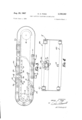
- FIG. 1 is a plan, generally schematic view of the novel system shown generally in block diagram
- FIG. 2 is a sectional elevational view of the apparatus in FIG. 1, taken on plane II-II;
- FIG. 3 is an enlarged side elevational fragmentary view of a portion of the novel system
- FIG. 4 is a sectional view taken on plane IV-IV of FIG. 3;
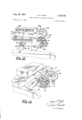
- FIG. 5 is a fragmentary enlarged perspective top view of a portion of the conveyor apparatus, showing part of the control means at the loading zone of the conveyor;
- FIG. 6 is an enlarged fragmentary perspective view of the control means in FIG. 5;
- FIG. 7 is a top plan view of the control means in FIGS. 5 and 6;
- FIG. 8 is a sectional view taken on plane VIII-VIII in FIG. 7;
- FIG. 9 is an enlarged fragmentary view of a portion of the apparatus in FIG. 8; 7
- FIG. 10 is a side elevational fragmentary view of the propelling means of the conveyor apparatus, showing the individual dogs mounted on the propelling member and the operation of the dog releasing camming members at the loading zone;
- FIG. 11 is a fragmentary perspective view of the unloading zone of the conveyor apparatus
- FIG. 12 is a perspective fragmentary view of the loading zone in FIG. 11, taken from the opposite side, with an unloaded platform shown passing through the unloading zone;
- FIG. 13 is a perspective view of the unloading zone in FIG. 12, shown with a loaded platform at rest;
- FIG. 14 is a fragmentary side elevational view of a portion of the propelling means, showing its function at the unloading zone;
- FIG. 15 is a schematic diagram of an alternate electrical control means for the conveyor of the type shown with the mechanical control means in FIGS. 1 through 1
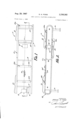
- the complete conveyor assembly 10 is an elongated structure which includes a pair of cooperative recirculatory track means 12 and 12 on opposite sides of the conveyor, interconnected by braces 14, and mounted on vertical supports 16.
- the conveyor has a loading zone 18 shown to be on one end of the conveyor, an unloading zone 20 shown to be on the opposite end, and a storage zone 22 shown on the lower return run.
- Mounted on the tracks to recirculate thereon through the upper run and the lower return run is a plurality of articulated platforms, a few of which, 24a, 24b and 240, are shown.
- Each platform is articulated to pass through the return end bends between the upper run and the lower run, such bends being shown clearly in FIG. 2 for example.
- Each articulated platform includes a plurality of load supporting transverse members here shown to be two in number as the front member 2512 and rear member 26b of platform 24b (FIG. 1). These members are interconnected on their ends by a plurality of roller chain links 26b mounted on enlarged rollers or wheels 27b. These links and rollers are captively retained in the guide tracks as shown by the rollers of platforms 24d, 24:: and 24 in track 12 (FIG. 3).
- the upper run is shown with guide tracks having both upper and lower retention plates while the lower run is shown with only a lower plate.
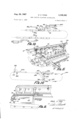
- the individual articulated captive platforms can be propelled along the conveyor by propelling means that includes a flexible, endless propelling member such as roller chain 30 extending through the center of the apparatus between the tracks. It travels along the upper run, returning on the lower path, and rounding the end bends on sprockets 42.
- propelling means that includes a flexible, endless propelling member such as roller chain 30 extending through the center of the apparatus between the tracks. It travels along the upper run, returning on the lower path, and rounding the end bends on sprockets 42.
- a plurality of platform engaging dog assemblies 32 are pivotally attached to the chain to recirculate with it.
- each dog has a pivotal connection 32a to chain 30 at the leading end of the dog, has a pair of cam follower rollers 32b projecting above it (in the upper run) intermediate its ends, and has a platform engaging hook 320 at its opposite trailing end.
- the free trailing end 32c of each dog is biased away from the chain 30 and toward the platform by a biasing spring such as spring 32d (FIG. 10) which extends from a fixed connection at one of its ends to chain 30, around pivotal point 32a, around the rotational axis of cam followers 32b, and having its other end engaged to the trailing end of the dog.
- the dog hooks extend upwardly on the upper run, and downwardly on the lower run.
- Roller chain 30, in its upper run, is guided and retained in a generally U-shaped, upwardly oriented channel 40.
- the chain can be driven by powering sprocket 42 at the downstream end (FIG. 11). This is done by mounting sprocket 42 on shaft 44 to which another sprocket 46 is mounted.
- Sprocket 46 is driven by drive chain 48 from a suitable motor-gear box combination 5]. covered by protective panel 53.
- chain 30 As chain 30 is continuously driven around its recirculatory pattern through the upper run and lower run, it moves the spaced dog assemblies 32 along with it.
- the dog assemblies are normally biased by the spring elements contained within them into a position to engage the platforms to drag the platforms around the assembly in a captive fashion.
- platforms Although only a few platforms are shown for illustrative purposes, it will be realized that great many platforms of selected number can be utilized on the assembly, depending upon the length and the use of the conveyor involved.
- the number of platforms can be many times greater than the number of towing dogs on the chain because the platforms will accumulate, as in the storage zone. The accumulation occurs because of the cooperability of each dog assembly 32 with a platform ahead of it.
- the dog is positioned to engage the towing bar opening in the front end of the platform being towed, as shown for example in FIG. 10. Since the cam followers 32b on the dog project out ahead of the towed platform (as shown by dog 32 and platform 24d in FIG. 3), when the dog encounters a platform eg 242 immediately ahead of it, rollers 32b are depressed against the bias of the dog spring by engagement with the camming plate 24g (for example on carrier 242) to depress the hook 320 out of engagement with front towing plate 2411 of platform 24d.
- Such a dog can traverse an entire series of accumulated platforms without engaging them in towing fashion, and will only engage the frontmost platform. With this apparatus, this engagement with the foremost platform is controlled also, as will be explained more fully hereinafter.
- the platforms are provided with a resilient bumper type impact absorbing member 24 (FIG. on the front end of each of the platforms so as to absorb the impact when a dog accelerates the platform from a dead stop to full speed.
- This member extends through the front support plate of the platform and includes a coil spring 24k to absorb the impact.
- control means which automatically govern the engagement and disengagement of specific platforms with one of the recirculating dogs on chain 30.
- This control means includes a control subassembly 50 at the loading zone 18 (FIGS. 1, 2 and 5 through 8) and storage zone 22. That is, control subassembly 50 controls the advancement of individual unloaded platforms from storage zone 22 to the loading zone in relation to advancement from the loading zone.
- the control means also includes a control subassembly 52 at the unloading zone of the conveyor apparatus (FIGS. 1, 2 and 11 through 13).
- control subassembly 50 in the preferred form of the invention it comprises a mechanical apparatus responsive to the presence of an unloaded carrier at the loading zone, and subsequently responsive to the loaded characteristic of the platform in this loading zone.
- roller 27b As roller 27b passses along suming that platform 24d is just rounding the bend and approaching the loading zone, so that its front end is on the upper run, and its rear end is still on the lower run as shown, when the frontmost roller wheels 7215 advance along the track section 12a, (FIG. 5) toward the split 12b between short track section 12a and the remainder of track 12, as shown by the phantom wheel in FIG. 5, the wheels force section 12a to shift.
- the space between the upper and lower flanges of section 12a at its downstream end is less than the diameter of roller 27b.
- top flange is fixed and the lower flange pivots about pivots 12a it forces the lower flange down against upwardly biasing spring 60 to make the space between the upper and lower flange of 12a equal to its diameter.
- transverse bar 62 is depressed.
- Depression of bar 62 depresses essentially vertically extending link 64 affixed to bar 62 (FIG. 5 and 6).
- Depression of link 64 causes depression of pivot pin 68. Since pin 68 is affixed to link 70, this link 70 is arcuately depressed because one end of link 70 is fixed to a rotational bar 72, The reason for this linkage is to provide a mechanical advantage so that the free end of link 70 will be derpessed several times the actual depression of the track portion 12a.
- link 70 is pivotally connected by bolt 74 to a vertical link 76, which has an upper cam 78 and a lower cam 80 attached thereto.
- this set of linkage means is duplicated on the opposite side of the control subassembly 50 as shown in FIGS. 7 and 8.
- Cooperative respectively with the cams 78 and 80 are independently operating dog shifting units 84 and 86 (FIG. 8) which control dogs 32 in the loading zone and the storage zone respectively.
- shifting unit 84 includes a pair of like dog camming plates 84a and 84b rigidly interconnected by a lower cross plate 84c and mounted on a plurality of four vertical guide bolts 88 by a plurality of outwardly projecting orificed bosses 84d.
- Flanges 84f cooperate with cams 78.
- Members 84a through 84d and 84 are rigidly interconnected so that they move as a unit.
- the bosses 84d rest upon coil springs 90 around the rods or bolts 88 so that these members are biased upwardly so that plates 84a and 841) are in the upwardly projecting position shown generally in FIGS. 5 and 8.
- Lowering of unit 84 is achieved by depression of cams 78 against the bias of these coil springs 90. Normally, in the absence of a platform in the loading zone, cams 78 are spaced above the outwardly projecting following plates 84f of unit 84 in the manner illustrated in FIGS. 6 and 8. When an unloaded platform partially depresses track section 12a as described above, cams 78 are brought down to engage flanges 84 but do not yet depress them.
- the lower dog shifting unit 86 that projects down into the end of the platform storage zone is mounted somewhat independently from the upper dog shifting unit 84. More specifically, this lower unit includes a pair of depending horizontally projecting cam plates 86a and 86b which are rigidly interconnected by an upper cross plate 860 includes a pair of outwardly projecting flanges 86d which vertically slidably mount unit 86 on four separate slide bolts so that this unit 86 is freely movable up and down on these bolts without any biasing spring.
- the force of gravity allows unit 86 to drop when the cam elements 80 beneath flanges 86d drop. These drop when an unloaded carrier enters the loading zone and partially depresses track section 12a as described above.
- This unit and control subassembly The principle of operation of this unit and control subassembly is to cause camming elements 80 to drop a first predetermined distance when the unloaded platform enters the loading zone, as described above (FIG. 5), and then subsequently, when a load is placed upon the platform, it causes track section 12a to drop further against the bias of spring 60 (FIG. 5), until track section 12a and track section 12 are aligned, to cause upper earns 78 to depress the upper control unit 84.
- the first shift prevents unloaded storage platforms from moving up to the loading zone when one unloaded platform has reached the loading zone.
- the second shift releases the loaded platform from the loading zone to travel along the conveyor.
- control means 52 When the loaded platform enters unloading-zone 20, the control means 52 comes into play. More specifically, referring to FIGS. 11, 12 and 13, control means 52 includes a pair of interconnected vertically shiftable dog shifting elements 110a and 11% shiftable from a lowered position (FIGS. 11 and 12) (which they maintain when no carrier is present or when an unloaded carrier is present), to a raised position which they assume when a loaded carrier is present (FIG. 13). In the lowered position of these elements 110a and 11017 (FIG. 14), dogs 32 can continue to pull the unloaded platforms past the unloading zone and back to the storage zone on the lower run of the conveyor.
- FIG. 11 and 12 which they maintain when no carrier is present or when an unloaded carrier is present
- a raised position which they assume when a loaded carrier is present
- This link is pivotally afiixed near one end but intermediate its ends to a fixed pivot member 146 attached to rigid bar 148.
- downward shifting of bar 140 and leg 142 causes upward shifting of the opposite end of link 144, to shift elements 110a and 110b upwardly, so that the dog pulling this platform 24b is biased downwardly to a release position as can be visualized from FIG. 14.
- Subsequent dogs passing the loaded platform will also be biased downwardly so as not to pick up the platform until the load is relieved.
- the structure is also preferably formed so that the guide member 150 that guides the rollers of platform around the bend forms a positive stop when the track section is pivoted downwardly, as shown in FIG. 13. This prevents any possibility of the platform gravitating around the bend to dump the load on the floor. When the load is removed, the elements a and 110! will drop down to the inactive position to allow the next dog to pick up the platform for advancement to the storage zone.
- control means is completely responsive to the presence and condition of the articulated captive platforms.
- the system provides its own complete control by simple mechanism. Therefore, an entire series of platforms can be mounted on the conveyor, with individual platforms being removed from the storage zone to the loading zone as needed, and with individual platforms being advanced from the loading zone when loaded, to the unloading zone, where they are stopped.
- the dogs will be automatically depressed by the platforms immediately upstream of the engagement position of the succeeding platform so that the dogs will not advance another platform until controlled to do so.
- the dogs will be automatically biased by the leading platforms to cause the loaded platforms to accumulate on the upper. run of the conveyor. Therefore, the conveyor system provides complete control.
- the mechanical type of mechanism like the one form of mechanical control shown is employed.
- an electrical control system like that'shown schematically in FIG. 15 may be employed.
- the conveyor likewise includes the tracks and platforms of the type illustrated previously.
- the camming plates 1'84 and 186 for the loading zone and storage zone respectively can be actuated through suitable limit switches.
- a platform approaches the loading zone, it is released from the driving dog by camming plates 184.
- limit switch 250 to activate solenoid 252 or some other power means, which shifts the camming plates 184 to an inactive position, allowing the next dog on the chain to pick up the platform and advance it to the unloading zone.
- the loaded platform trips another limit switch 260 which trips solenoid 262 to shift camming plates 86 to inactive position, to allow a dog to engage the foremost platform and advance it from the storage zone to the loading zone.
- this platform moves out of the storage zone to the load ing zone, it trips a limit switch 270 which again actuates solenoid 262 to place camming plates 186 in a dog shifting position. Therefore, only one unloaded platform will be advanced from the storage zone at -a time until solenoid 262 'is again actuated by limit switch 260. As the loaded platform moves to the unloading zone and depresses track section 212e, this tnack section trips limit switch 280, which operate solenoid 2-82 for camming plates 210, to cause the dogs to release from the loaded platform until it is unloaded. At that time, the limit switch will be relieved by biasing of the track section upwardly again.
- a conveyor system comprising: recirculatory conveyor track means including an upper run and a lower run connected by return bends; a plurality of captive, loadable, recirculatory platforms mounted on said track means to move therealong, each of said captive platforms being articulated along its length to traverse said return bends; propelling means along said track means including platform engaging means engageable and disengageable with said articulated platforms; and engagement control means operably associated with said platform engaging means and said platforms to selectively advance individual platforms along said track means.
- a conveyor system comprising: recirculatory conveyor track means; a plurality of recirculatory platforms captively mounted on said track means, said conveyor system including at least one platform loading zone, at least one platform unloading zone, and at least one platform storage zone, sequentially located in that order; said conveyor including platform propelling means having platform engaging dogs engageable with and disengageable from said platforms; and control means to cause dog engagement with a platform at said loading zone when such platform is loaded, to cause dog disengagement with a loaded platform at said unloading zone until such platform is unloaded, to cause dog engagement with a platform at said unloading zone when such platform becomes unloaded to move it to said storage zone, and to cause dog engagement of an unloaded platform at said storage zone upon engagement of a dog with a loaded platform at said loading zone, to replace the loaded platform in said loading zone with an unloaded platform.
- An accumulator platform conveyor system for pallets and the like comprising: recirculatory conveyor track means forming an upper conveyance run and a lower return run connected by return bends; a plurality of pallet conveying platforms mounted in captivity on said track means; each of said platforms being articulated to form a loadable platform on said upper run and to traverse said return bends; platform propelling means along said conveyor system, including platform engaging dogs engageable with and disengageable from said platforms; said conveyor system including at least one platform loading zone and at least one platform storage zone; control means cooperative with said loading zone to cause dog engagement with a loaded platform at said loading zone to advance it therefrom, and cooperative with said storage zone to cause dog engagement with an unloaded platform at said storage zone with advancement of said loaded platform from said loading zone; and said dogs being cooperative with platforms immediately ahead thereof to disengage an engaged platform when at least two of said platforms have accumulated.
- control means includes weight responsive means at said loading zone responsive to a loaded platform and operably associated with said platform engaging means to cause engagement of said engaging means with such loaded platform.
- control means includes weight responsive dog shifting means at said loading zone responsive to a loaded platform to enable do g engagement with the loaded platform.
- the conveyor system in claim 1 including a platform loading zone and a platform storage zone; said control means includes platform responsive means at said loading zone and actuating means at said storage Zone capable of controlling platform engagement by said engaging means, and said platform responsive means is operably associated with said actuating means to prevent the engaging means from propellably engaging a platform in said storage zone for advancement thereof to said loading zone while another platform is present at said loading zone.
- said engaging means comprises a plurality of independent shiftable dogs biased into engagement with said platforms and including cam follower means engageable with said platform immediately ahead thereof to shift the dog out of engaging position.
- control means includes weight responsive dog shifting means at said unloading zone responsive to a loaded platform to shift the engaged dog and subsequent dogs out of engagement therewith until said loaded platform is unloaded.
- said control means includes dog shifting means at said storage zone and at said loading Zone and includes actuating means at said loading zone; said actuating means being responsive to the presence of an unloaded platform at said loading zone and operably connected to said shifting means at said storage zone to prevent operative engagement of a dog with a platform at said storage zone to advance it to said loading zone, and said actuating means being responsive to the presence of a loaded platform at said loading zone and operably connected to said shifting means at said loading zone to allow operative dog engagement with said loaded platform to advance it along said upper run.
Landscapes
- Engineering & Computer Science (AREA)
- Mechanical Engineering (AREA)
- Intermediate Stations On Conveyors (AREA)
Priority Applications (7)
| Application Number | Priority Date | Filing Date | Title |
|---|---|---|---|
| US556473A US3338382A (en) | 1966-06-09 | 1966-06-09 | Semi-captive platform accumulator |
| NL6705073A NL6705073A (ref) | 1966-06-09 | 1967-04-11 | |
| BE698130D BE698130A (ref) | 1966-06-09 | 1967-05-08 | |
| FR105728A FR1522130A (fr) | 1966-06-09 | 1967-05-09 | Transporteur de palettes à plates-formes semi-asservies |
| DE19671531013 DE1531013A1 (de) | 1966-06-09 | 1967-05-31 | Foerderer |
| ES341541A ES341541A1 (es) | 1966-06-09 | 1967-06-08 | Una instalacion transportadora. |
| GB26870/67A GB1189462A (en) | 1966-06-09 | 1967-06-09 | Improvements in and Relating to Conveyor Systems |
Applications Claiming Priority (1)
| Application Number | Priority Date | Filing Date | Title |
|---|---|---|---|
| US556473A US3338382A (en) | 1966-06-09 | 1966-06-09 | Semi-captive platform accumulator |
Publications (1)
| Publication Number | Publication Date |
|---|---|
| US3338382A true US3338382A (en) | 1967-08-29 |
Family
ID=24221471
Family Applications (1)
| Application Number | Title | Priority Date | Filing Date |
|---|---|---|---|
| US556473A Expired - Lifetime US3338382A (en) | 1966-06-09 | 1966-06-09 | Semi-captive platform accumulator |
Country Status (6)
| Country | Link |
|---|---|
| US (1) | US3338382A (ref) |
| BE (1) | BE698130A (ref) |
| DE (1) | DE1531013A1 (ref) |
| ES (1) | ES341541A1 (ref) |
| GB (1) | GB1189462A (ref) |
| NL (1) | NL6705073A (ref) |
Cited By (9)
| Publication number | Priority date | Publication date | Assignee | Title |
|---|---|---|---|---|
| US4088220A (en) * | 1975-05-20 | 1978-05-09 | W. & M. Automation Karl Muller | Endless conveyors for the horizontal rotary conveyance of objects |
| US4896763A (en) * | 1988-05-25 | 1990-01-30 | Rmt Engineering Ltd. | Transport system |
| US5178261A (en) * | 1991-05-30 | 1993-01-12 | Auto/Con Corporation | Conveyor system |
| US5220996A (en) * | 1992-04-27 | 1993-06-22 | Valiant Machine & Tool Inc. | Conveyor system |
| US6318546B2 (en) * | 1997-12-24 | 2001-11-20 | Lawson Automotive Inc. | Pallet retention and release system |
| US6464066B2 (en) * | 2000-04-04 | 2002-10-15 | Inno-Veyor, Inc. | Conveyor assembly with pallet coupling |
| US6662930B2 (en) | 2001-07-31 | 2003-12-16 | Metso Minerals Industries Inc. | Apron weigh feeder |
| US20040231964A1 (en) * | 2001-06-25 | 2004-11-25 | Hafner Hans Wilhelm | Chain conveyor in the form of scales |
| US20090065330A1 (en) * | 2007-09-07 | 2009-03-12 | Dematic Corp. | Conveyor systems |
Families Citing this family (1)
| Publication number | Priority date | Publication date | Assignee | Title |
|---|---|---|---|---|
| US4483252A (en) * | 1982-09-28 | 1984-11-20 | Jervis B. Webb Company | Power and free conveyor and pusher assembly therefor |
Citations (6)
| Publication number | Priority date | Publication date | Assignee | Title |
|---|---|---|---|---|
| US1492178A (en) * | 1922-05-31 | 1924-04-29 | Harry E Nicholas | Apparatus for use in canning and other industries |
| US1516049A (en) * | 1923-05-05 | 1924-11-18 | Oliver P Luetscher | Apparatus for casting |
| DE960103C (de) * | 1955-06-15 | 1957-03-14 | Phoenix Rheinrohr Ag Vereinigt | Vorrichtung an Zulaufrollgaengen fuer Waermoefen zum periodischen Anhalten mehrerer, auf dem Rollgang kontinuierlich anfallender kurzer Walz- oder aehnlicher Erzeugnisse |
| US2787364A (en) * | 1952-11-20 | 1957-04-02 | Fmc Corp | Automatic self-filling conveyor |
| DE973322C (de) * | 1952-12-05 | 1960-01-21 | Stotz Ag A | Fliessbandfoerderanlage, insbesondere fuer Giessereihallen |
| US3117668A (en) * | 1962-01-22 | 1964-01-14 | Adams Mfg Co Inc | Conveyor for dishwasher |
-
1966
- 1966-06-09 US US556473A patent/US3338382A/en not_active Expired - Lifetime
-
1967
- 1967-04-11 NL NL6705073A patent/NL6705073A/xx unknown
- 1967-05-08 BE BE698130D patent/BE698130A/xx unknown
- 1967-05-31 DE DE19671531013 patent/DE1531013A1/de active Pending
- 1967-06-08 ES ES341541A patent/ES341541A1/es not_active Expired
- 1967-06-09 GB GB26870/67A patent/GB1189462A/en not_active Expired
Patent Citations (6)
| Publication number | Priority date | Publication date | Assignee | Title |
|---|---|---|---|---|
| US1492178A (en) * | 1922-05-31 | 1924-04-29 | Harry E Nicholas | Apparatus for use in canning and other industries |
| US1516049A (en) * | 1923-05-05 | 1924-11-18 | Oliver P Luetscher | Apparatus for casting |
| US2787364A (en) * | 1952-11-20 | 1957-04-02 | Fmc Corp | Automatic self-filling conveyor |
| DE973322C (de) * | 1952-12-05 | 1960-01-21 | Stotz Ag A | Fliessbandfoerderanlage, insbesondere fuer Giessereihallen |
| DE960103C (de) * | 1955-06-15 | 1957-03-14 | Phoenix Rheinrohr Ag Vereinigt | Vorrichtung an Zulaufrollgaengen fuer Waermoefen zum periodischen Anhalten mehrerer, auf dem Rollgang kontinuierlich anfallender kurzer Walz- oder aehnlicher Erzeugnisse |
| US3117668A (en) * | 1962-01-22 | 1964-01-14 | Adams Mfg Co Inc | Conveyor for dishwasher |
Cited By (11)
| Publication number | Priority date | Publication date | Assignee | Title |
|---|---|---|---|---|
| US4088220A (en) * | 1975-05-20 | 1978-05-09 | W. & M. Automation Karl Muller | Endless conveyors for the horizontal rotary conveyance of objects |
| US4896763A (en) * | 1988-05-25 | 1990-01-30 | Rmt Engineering Ltd. | Transport system |
| US5178261A (en) * | 1991-05-30 | 1993-01-12 | Auto/Con Corporation | Conveyor system |
| US5220996A (en) * | 1992-04-27 | 1993-06-22 | Valiant Machine & Tool Inc. | Conveyor system |
| US6318546B2 (en) * | 1997-12-24 | 2001-11-20 | Lawson Automotive Inc. | Pallet retention and release system |
| US6464066B2 (en) * | 2000-04-04 | 2002-10-15 | Inno-Veyor, Inc. | Conveyor assembly with pallet coupling |
| US20040231964A1 (en) * | 2001-06-25 | 2004-11-25 | Hafner Hans Wilhelm | Chain conveyor in the form of scales |
| US6964550B2 (en) * | 2001-06-25 | 2005-11-15 | Pfister Gmbh | Chain conveyor in the form of scales |
| US6662930B2 (en) | 2001-07-31 | 2003-12-16 | Metso Minerals Industries Inc. | Apron weigh feeder |
| US20090065330A1 (en) * | 2007-09-07 | 2009-03-12 | Dematic Corp. | Conveyor systems |
| US7909155B2 (en) | 2007-09-07 | 2011-03-22 | Dematic Corp. | Conveyor systems |
Also Published As
| Publication number | Publication date |
|---|---|
| GB1189462A (en) | 1970-04-29 |
| BE698130A (ref) | 1967-11-08 |
| DE1531013A1 (de) | 1969-10-16 |
| ES341541A1 (es) | 1968-07-01 |
| NL6705073A (ref) | 1967-12-11 |
Similar Documents
| Publication | Publication Date | Title |
|---|---|---|
| CA1316139C (en) | Sortation equipment | |
| US3960262A (en) | Accumulating conveyor | |
| US3338382A (en) | Semi-captive platform accumulator | |
| US3662906A (en) | Conveyor systems | |
| US2949862A (en) | Overhead truck pusher conveyor | |
| US3369648A (en) | Vertical sorting system | |
| US4232779A (en) | Infeed assembly and a discharge assembly for a conveyor system | |
| US3592333A (en) | Cargo-handling system and method | |
| US3156345A (en) | Motor powered accumulating conveyor | |
| US2832297A (en) | Arrangement for warehousing merchandise | |
| US1297680A (en) | Conveyer system. | |
| US2812724A (en) | Conveyor systems | |
| US2844241A (en) | Conveyor systems | |
| US3503337A (en) | Accumulating conveyor system | |
| US3399768A (en) | Lumber or board sorting apparatus | |
| US3706286A (en) | Conveyor systems | |
| US1219900A (en) | Loading mechanism for package-conveyers. | |
| US2987011A (en) | Conveyor interchange | |
| US2921008A (en) | Processing conveyor apparatus | |
| US3503338A (en) | Subfloor conveyor tow trucks | |
| US3424104A (en) | Conveyor apparatus | |
| US3915287A (en) | Conveyor system | |
| US3048125A (en) | Conveyor systems | |
| US3477388A (en) | Entrance switch for power and free conveyors | |
| US3568818A (en) | Conveyor for accumulating, spacing and storing articles |