US3338024A - Method and apparatus for executing in an automatic packing machine a container wrapping, adapted to wrap delicate products having also a non-parallelepiped shape - Google Patents
Method and apparatus for executing in an automatic packing machine a container wrapping, adapted to wrap delicate products having also a non-parallelepiped shape Download PDFInfo
- Publication number
- US3338024A US3338024A US365534A US36553464A US3338024A US 3338024 A US3338024 A US 3338024A US 365534 A US365534 A US 365534A US 36553464 A US36553464 A US 36553464A US 3338024 A US3338024 A US 3338024A
- Authority
- US
- United States
- Prior art keywords
- wrapping
- product
- elevator
- edges
- packing
- Prior art date
- Legal status (The legal status is an assumption and is not a legal conclusion. Google has not performed a legal analysis and makes no representation as to the accuracy of the status listed.)
- Expired - Lifetime
Links
Images
Classifications
-
- B—PERFORMING OPERATIONS; TRANSPORTING
- B65—CONVEYING; PACKING; STORING; HANDLING THIN OR FILAMENTARY MATERIAL
- B65B—MACHINES, APPARATUS OR DEVICES FOR, OR METHODS OF, PACKAGING ARTICLES OR MATERIALS; UNPACKING
- B65B11/00—Wrapping, e.g. partially or wholly enclosing, articles or quantities of material, in strips, sheets or blanks, of flexible material
- B65B11/06—Wrapping articles, or quantities of material, by conveying wrapper and contents in common defined paths
- B65B11/18—Wrapping articles, or quantities of material, by conveying wrapper and contents in common defined paths in two or more straight paths
- B65B11/20—Wrapping articles, or quantities of material, by conveying wrapper and contents in common defined paths in two or more straight paths to fold the wrappers in tubular form about contents
- B65B11/22—Wrapping articles, or quantities of material, by conveying wrapper and contents in common defined paths in two or more straight paths to fold the wrappers in tubular form about contents and then to form closing folds of similar form at opposite ends of the tube
-
- B—PERFORMING OPERATIONS; TRANSPORTING
- B65—CONVEYING; PACKING; STORING; HANDLING THIN OR FILAMENTARY MATERIAL
- B65B—MACHINES, APPARATUS OR DEVICES FOR, OR METHODS OF, PACKAGING ARTICLES OR MATERIALS; UNPACKING
- B65B43/00—Forming, feeding, opening or setting-up containers or receptacles in association with packaging
- B65B43/08—Forming three-dimensional [3D] containers from sheet material
- B65B43/10—Forming three-dimensional [3D] containers from sheet material by folding the material
Definitions
- This invention relates essentially to wrapping machine for wrapping products of a delicate nature and having also a non-parallelepiped shape and wherein more than one wrapping are used comprising a parchment or inner papers, an intermediate cardboard and a printed outer paper.
- the packing machine performing such method is destined to wrap convex oval soaps which are not yet in hardened condition.
- This problem specifically interests the wrapping of packing of fine quality toilette soaps and the invention provides a solution of this problem, consisting in modifying and improving a soap wrapping machine causing the forward motion (feed) of the product by means of a belt conveyor subjected to an intermittent motion and the feed over differentiated sections of the wrapping material, supplied from a plurality of coils (see in this respect the Italian Patents Nos. 580,- 830 and also 626,985 regarding the fitting of a tearoif strip).
- a packing machine having a conveyor, constituted of a belt provided with toothing on one face thereof and driven by at least a driving pulley, provided with notches in the form of cylindrical cavities or the like, corresponding to the teeth of the aforementioned belt, the pulley being actuated by suitable means, which are capable of imparting to the same an intermittent constant step feed, the driving means being normally of the type usually used in packing machines with intermittent feed, the device being characterized by the fact that on the outer face of the aforesaid belt there are provided spacing means, spaced from one another by a distance corresponding to the length of the feed step.
- Such a conveyor system ensures, in fact, a continuous feed of the product, without causing impacts against the edges between a product and the adjacent one as occurs in the use of a belt conveyor of the known type.
- a controlled transverse pusher adapted to act on the product which comes into the pickup zone at the end of the feed belt, said pusher being substantially adapted to displace the product from the pick-up zone to the packing or wrapping zone together with clamp means, adapted to transfer the three wrapping blanks from a respective pick-up zone to the wrapping or packing zone itself.
- the packing or wrapping assembly is provided with a complex elevator, composed of a number of members, adapted to accomplish together at least an elevation stroke, whilst before the start and at the end of the same there are provided relative motions for one only of the parts composing the elevator as compared to the other ones and the support frame as well, furthermore along the first length of the trajectory of the elevator there is a station zone, in which controlled benders or folders are located, having a concomitant action in direction of the product and adapted to act upon part of the cardboard edges, whilst on the outer side of the elevator there are arranged stopping means for the folded edges or flaps.
- a complex elevator composed of a number of members, adapted to accomplish together at least an elevation stroke, whilst before the start and at the end of the same there are provided relative motions for one only of the parts composing the elevator as compared to the other ones and the support frame as well, furthermore along the first length of the trajectory of the elevator there is a station zone, in which controlled benders or folders are located, having
- a transverse bender controlled in such a way as to bend the three wrapping materials underneath the product handled by the elevator and towards the support zone thereof, further a conveyor such as for example a pusher or a comb member is arranged in such a way as to act, when actuated in the direction of the package and to shift the same transversely, a stationary bender being provided on the sliding plane of such package, and adapted to execute a further folding of the three wrappings on the lower face of the product towards the formerly folded edges on the same face by means of the aforesaid transverse bender, in such a way that both ends of the cardboard edges meet with each other on the same plane, whilst the outer wrapping edges are covered up and the inner parchment paper directly wraps the product.
- a conveyor such as for example a pusher or a comb member is arranged in such a way as to act, when actuated in the direction of the package and to shift the same transversely, a stationary bender being provided on the sliding plane of such package, and adapted to
- FIGS. 1, 2, 3, 3a, 3b, 3c, 4 show the various wrapping or packing stages of a product (consisting of an oval soap) which are accomplished according to the invention by a mechanical equipment illustrated in other figures;
- FIG. 1 being a front elevation showing a first stage
- FIG. 2 being a side elevation looking at the left of FIG. 1;
- FIG. 3 being a side elevation similar to FIG. 2, but showing a second stage
- FIG. 3a being an elevation looking at the left of FIG. 3;
- FIG. 3b being a side elevation similar to FIG. 3, but showing a further stage
- FIG. 3 being an elevation looking '-at the left of FIG. 3b;
- FIG. 4 showing still further stages, viewed similarly to FIGS. 3 and 3b.
- FIGS. 5, 5a and 5b show various possible wrapping shapes or packages obtainable with the same packing method and equipment
- FIG. 6 ShOWs a plan view of a pick-up, centering and presetting assembly for three wrapping blanks and including the means for moving the three wrapping blanks towards the adjacent packing zone;
- FIG. 7 shows the wrapping blanks already in the starting position of the packing cycle, when the product is carried on an elevator after being picked-up from a step conveyor; (FIGS. 6 and 7 are shown displaced with respect to each other; in practice member 13 in both figures are aligned);
- FIG/7a shows such conveyor in elevation, comprising a conveyor belt with inner-toothing, which is externally provided with spacing members, for various product pieces, spaced from each other by a distance corresponding to the length of the feed step of thestep feeder;
- FIG. 8 shows in a plan view the top of an elevator, on which a piece of oval soap is arranged, whilst sideways of the elevator there is disposed a plane for the support of the product during its transfer from the belt conveyor to the elevator;
- FIGS. 9 and 9a show a lateral view of the head of the elevator in the raised position during the first wrapping stage, during which the folding of the main front edges occurs, it being further noticeable from such figures that bending members are provided and a transposition of the elevator in a subsequent upward station position is also observed along the vertical trajectory of the elevator, whilst in the same figures there is represented a counterelevator, movable in the same direction as the underlying elevator;
- FIGS. 10 and 10a complete the preceding figures, showing the same mechanical assembly rotated by 90 and in which the elevator is provided with support and stem control means, feed means for the product being further shown at right-hand side of the figure, and in the intermediate zone, between the above-mentioned station positions being located stationary benders for an intermediate folding stage, in FIGURE 10a being further represented a detail pertaining to a folding stage of the reinforcing front edges, taking place at the upper station and the start of which implies a movement of the benders in both directions indicated by the arrows shown in the station zone, finally in the same figures being represented a subsequent folding stage of the wrapping blanks over a part of the lower face of the product; 7
- FIG. 11 shows in side elevation a pick-up stage of the package from the elevator and a folding stage of another part of the wrapping blanks over the remaining part of the lower face of the product, said elevator not being shown herein for the sake of clearness, also because same may be noticed from other figures, the pick-up operation being in this case carried out by means of a comb;
- FIG. 12 represents in elevation and in a closely analogous manner to the preceding figure, the same pick-up and completion stages of the wrapping operation, carried out with the use of a pusher, such both systems substantially attaining the same object
- FIG. 13 shows in elevation and in cross section a comb as per FIG. 11 while taking off a package from a corresponding not shown support, whilst the counter-plate cooperates with the afore-mentioned counter elevator and acts in such case as a guide for the product shown herein.
- FIG. 1 a forming stage of the Wrapping of the product P will be noted therefrom consisting in the folding of the main edges 1a and 1b of the cardboard 1 over the front ends of the soap.
- a second stage as per FIG. 2 in which the package is shown rotated by there occurs the downward folding of the side edges of the wrapping blanks. From the representations of both FIGURES 1 and 2 only a cardboard 1 (FIG. 1) and an outer wrapping 2 (FIG. 2 are shown, since for simplicity reasons an inner parchment paper wrapping up directly the product is omitted.
- FIG. 3 one may note the folding of the ends 201a and 301a of side edges or fiaps 201, 301 of the cardboard and respectively 202a, 302a of the edges 202, 302 of the outer wrapping blank over the edges 1a and 1b of the head parts, folded over in the first folding stage (FIG. 1).
- the height of the end 201a and 301a of the side edges of the cardboard is substantially equal to the thickness of the product P to be wrapped, which packing when rotated by 90 will appear as in FIG. 3a.
- FIG. 3b shows a subsequent folding of the lower part of the edges 201 and 202 of the cardboard and of the outer wrapping blank over the lower face of the product, and such folding is carried out by the machine at the same station point as per FIG. 3 as will become apparent hereinafter.
- FIG. 30 shows the shape of the package as per FIG. 3b rotated by 90, whilst in FIG. 4 there will be seen a succession of folding stages taking place during a continuous or intermittent motion of the package in which there occurs the folding of the edges 301 and 302 on the remaining part of the lower face of the product and subsequently the last folding of the double front edges 402, 502 of the outer wrapping on the said front ends of the package with gluing or sealing operation.
- Each front end can, in fact, be formed of a main edge or flap 4, which is first folded towards the corresponding front end of the product and of two edges or flaps 5 which are in turn folded over on the first one will be kept in the same plane with the ends abutting against each other and in contact.
- the second case is closely analogous to the preceding case, the only difference consisting in having snipped the corners of edges 4a and 5a, 5b in order to substantially round off the corners of the package.
- the head or front end is accomplished only by the main edge or limb 4b, which by folding over the head or front limb of the tubular body of the cardboard will build a considerably consistent structure.
- the packing machine is provided with a feeder 6 (FIGS. 7, 7a), constituted of a belt 7 with an internal toothing 8, subjected to the control of at least a pulley 9, provided with cylindrical cavities 9a corresponding to the belt teeth, with which, as already mentioned, suitable driving means cooperate so as to impart to the belt a constant step forward motion, such driving means being of normal use in, and packing machines.
- a feeder 6 (FIGS. 7, 7a), constituted of a belt 7 with an internal toothing 8, subjected to the control of at least a pulley 9, provided with cylindrical cavities 9a corresponding to the belt teeth, with which, as already mentioned, suitable driving means cooperate so as to impart to the belt a constant step forward motion, such driving means being of normal use in, and packing machines.
- On the outer side of the belt there are likewise fastened the spacing members 10, spaced from one another by a distance corresponding to the length of the feed step.
- An intermittently controlled pusher 11 will displace during the dwell of the conveyor, the product P from a position
- a photoelectrical device or the like permits to center the outer printed paper by imparting to the same if necessary eg a return motion whilst a second similar device F2 controls the return run of the shape-punched strip of the cardboard to ensure the step retention. Furthermore, the parchment paper is advanced in the desired measure without particular correction.
- Position B corresponds to position B of FIG. 9.
- a plate 15 which is flush with the level of the belt plane and provides support to the product during the sliding stage of the feeder towards an elevator, whilst a preferably rubber coated plate 16 (FIG. 8) is destined to support the product P in its center-of-gravity zone.
- Said plate 16 is mounted axially sliding over the internal zone in the head of an elevator with more members, which is well visible in its assembly from the FIGURES 8, 9, 10 and has the projections or fingers 17, which whilst raising have among other things the task of suitably centering the prouct.
- the first bender means 25 controlled by a lever 26 and a tie rod 27.
- the bender means are fulcrum-pivoted on the axes 28 and by means of toothed sectors 29, fast with the lever, are subjected to a simultaneous symmetrical action.
- the benders 25 act on the ends of the limbs 1a, 1b (main front limbs), which are folded downwardly without touching the outer wrapping blank.
- the four benders 32 Upon arrival of the product, entrained between the elevator means in the position B'l (FIG. 10 above), the four benders 32 simultaneously enter into operation, namely two benders at each end of the item to be packed.
- benders act on both ends in a symmetrical and concomitant manner under a selfcentering control, since they are in fact, controlled by a toothed pinion 33 with stationary axis 34 engaging on the racks 35 provided on the support rods of the benders.
- the return run of the main part of the elevator including the four fingers 17 then starts and as soon as the way is open the displacement of the lower transverse bender 36 begins, which folds over the wrapping blanks by bringing them nearly into contact with the vertical wall of the central support plate 16.
- FIG. 3b in which the package for representation purposes is rotated with respect to FIG. 10, namely, Whilst in FIG. 10 said bender 36 actively displaces from right to left-hand side, in FIG.
- Said support 16 is carried by the stem 216 and is maintained the upper position by the nose 37 (FIG. 10), acting against the counter means 38, fast with the rod 216.
- the nose 37 is fast with the limb 39 of a lever 40 carrying a stationary pin 41, on which a roller 42 is mounted.
- a clamp 43 Fast on the tubular stem 18 of the main elevator is a clamp 43 carrying a cam 44.
- the lower elevator proceeds further with its run down to the lower stroke end M, in which position the fingers 17 do not interfere with the passage of the product from position A to position B.
- the rod 216 and related center plate 16 are drawn back with a certain force by the spring 40, applied to the downwardly moving stem.
- the spring accelerates the mass which a moment earlier was without motion.
- a pneumatic brake is provided, consisting of an annular air chamber, not shown but easily deduceable and defined by the center part 316 of the plate and by the stem 216 and further completed with a circular housing provided on the hollow head of the elevator.
- the diameter of the piston and housing is bored in such 'a way as to leave a small clearance such as to stop the exit of the air stored therein thus creating the desired braking back-pressure.
- a rubber washer 50 adapted to keep up the position of mutual distance of the parts as desired thereby also contributing to the dampening action.
- the package may be directly moved by a comb member 53 (FIGS. 11, 13), subjected to an intermittent motion driving means of known type, or by a controlled pusher 54 (FIG. 12).
- the package is caused to travel and is guided within a guide way 55 or 555, sideways of which are provided for example the benders 56, 57 for the folding of the double limbs 402, 502 of the outer wrapping blank over the front ends (see also FIG. 4) and a gluing device 58, or one may provide helicoidal contour members 59, furthermore the package may be closed by means of a heat-sealing system.
- the aforesaid folding and gluing systems of the double head limbs of the outer wrapping may be considered as intuitive, since they contemplate the adoption of widely used devices.
- the feed system of the Wrapping materials may be such as to deliver already cut paper blanks for the intermediate cardboard, the outer wrapping and/ or inner parchment paper as well.
- A- packing machine for wrapping bodies offa delicate nature and of a non-parallelepiped shape in a plurality of wrappings, comprising means for feeding the wrapping material in a pick-up station, means for picking up the wrappings from the pick-up station and transferring them to a wrapping station, belt conveyor means for feeding the body to be packaged towards the wrapping station, said belt conveyor means having spacing members defining compartments for receiving on said belt conveyor single bodies to be packaged, pusher means to push said body from said belt conveyor towards the wrapping station, and bender means for folding the wrappings over said body, wherein the improvement comprises near said wrap?
- ping station B, B hollow tubular member (18) below said wrapping station (B, B said tubular member having four spaced apart fingers (17 fixed thereto and upwardly projecting therefrom beyond the upper end of the tubular member, said fingers being arranged in positions corresponding to the upper corners of thepackage to be formed and having edges corresponding to the edges of the corners of the package to be formed, said fingers being adapted to support the wrappings and to allow the wrapping to be folded over the edges of the corner shape defined by said fingers, a stem (216) coaxial with and slidably arranged within said tubular member (18), said stem carrying a supporting plate (16) at the upper end thereof, said supporting plate (16) projecting normally beyond the upper end of said tubular member (18) and being arranged in the vertical axis of symmetry of said corners defined by said fingers (17) to support the body to be wrapped in the zone of its center of gravity line, and means for imparting a reciprocating vertical movement to said tubular member (18).
Landscapes
- Engineering & Computer Science (AREA)
- Mechanical Engineering (AREA)
- Basic Packing Technique (AREA)
Description
Aug. 29, 1967 MAULIN] 3,338,024 5 METHOD AND APPARATUS FOR EXECUTING IN AN AUTOMATIC PACKING MACHINE A CONTAINER WRAPPING, DAPTED TO WRAP DELICATE PRODUCTS HAVING ALSO A N0N-PARALLELEPIPED SHAPE 4 Sheets-Sheet 1 Filed May 6, 1964 I K 3 l I l I l 402 j ga \ZON 302 62 302 .3c K 502 502 F9 INVENTOR.
Mouvizw MAULINI BY Age nf M.- MAULINI 3,338,024
ADAPTED .TO WRAP DELICATE NON-PARALLELEPIPED SHAPE 2 +v e G e N h T. s K C s A t P e e h s 4 XECUTING IN AN AUTOMATIC INVENTOR.
2L6 MALLLINl Mauri. BY
Aug. 29, 1967 METHOD AND APPARATUS FOR E MACHINE A CONTAINER WRAPPIN PRODUCTS HAVING ALSO A Filed May 6, 1964 I'll 3,338,024 PACKING Aug 29, 1967 M. MAULINI METHOD AND APPARATUS FOR EXECUTING IN AN AUTOMATIC MACHINE A CONTAINER WRAPPING, ADAPTED TO WRAP DELICATF PRODUCTS HAVING ALSO A NON-PARALLELEPIPED SHAPE 1964 4 Sheets-Sheet 3 v Filed May 6,
INVENTOR. Mauvizie MALLLINI BY A ent Aug. 29, 1967 M MAUUN; 3,338,024
. METHOD AND APPARATUS FOR EXECUTING INAN AUTOMATIC PACKING MACHINE A CONTAINER WRAPPING, ADAPTED TO WRAP DELICATE PRODUCTS HAVING ALSO A NON-PARALLELEPIPED SHAPE Filed May 6, 1964 4 Sheets-Sheet 4 INVENTOR. MaurLzLc MAULINI BY Flgenf United States Patent Ofilice,
3,338,024 Patented Aug. 29, 1967 3,338,024 METHOD AND APPARATUS FOR EXECUTING IN AN AUTOMATIC PACKING MACHINE A CON- TAINER WRAPPING, ADAPTED T WRAP DEL- ICATE PRODUCTS HAVING ALSO A NON-PAR- ALLELEPIPED SHAPE Maurizio Maulini, Bologna, Italy, assignor to Azionaria Costruzioni Macchine Automatiche A.C.M.A. S.p-A., Bologna, Italy Filed May 6, 1964, Ser. No. 365,534 Claims priority, application Italy, May 7, 1963, 9,507/ 63, Patent 695,254 1 Claim. (Cl. 53-203) This invention relates essentially to wrapping machine for wrapping products of a delicate nature and having also a non-parallelepiped shape and wherein more than one wrapping are used comprising a parchment or inner papers, an intermediate cardboard and a printed outer paper. Especially, the packing machine performing such method is destined to wrap convex oval soaps which are not yet in hardened condition. This problem specifically interests the wrapping of packing of fine quality toilette soaps and the invention provides a solution of this problem, consisting in modifying and improving a soap wrapping machine causing the forward motion (feed) of the product by means of a belt conveyor subjected to an intermittent motion and the feed over differentiated sections of the wrapping material, supplied from a plurality of coils (see in this respect the Italian Patents Nos. 580,- 830 and also 626,985 regarding the fitting of a tearoif strip).
It is one of the objects of this invention to reinforce the head portions of the package or wrapping containing the product, by means of three folded edges or flaps of the inner cardboard wrapping, the cardboard wrapping being delivered to the packing station in preferably cut and/or shape-punched condition according to a determined profile.
These and other important objects are attained by a packing machine having a conveyor, constituted of a belt provided with toothing on one face thereof and driven by at least a driving pulley, provided with notches in the form of cylindrical cavities or the like, corresponding to the teeth of the aforementioned belt, the pulley being actuated by suitable means, which are capable of imparting to the same an intermittent constant step feed, the driving means being normally of the type usually used in packing machines with intermittent feed, the device being characterized by the fact that on the outer face of the aforesaid belt there are provided spacing means, spaced from one another by a distance corresponding to the length of the feed step.
Such a conveyor system ensures, in fact, a continuous feed of the product, without causing impacts against the edges between a product and the adjacent one as occurs in the use of a belt conveyor of the known type.
On the packing machine according to this invention there is advantageously provided a controlled transverse pusher, adapted to act on the product which comes into the pickup zone at the end of the feed belt, said pusher being substantially adapted to displace the product from the pick-up zone to the packing or wrapping zone together with clamp means, adapted to transfer the three wrapping blanks from a respective pick-up zone to the wrapping or packing zone itself. Furthermore, in front of the pickup zone there are provided a cutting means for the wrappings themselves, as well as photoelectrical control devices and/or the like, adapted to ensure the centering of the printed outer wrapping paper thus causing, if necessary, the wrapping material, stored in the form of a tape, to accomplish a backward displacement, whereas another similar photoelectrical device is provided for the control of the position of the shape-punched strip or the like of the cardboard in such a way as to ensure step retention.
The packing or wrapping assembly is provided with a complex elevator, composed of a number of members, adapted to accomplish together at least an elevation stroke, whilst before the start and at the end of the same there are provided relative motions for one only of the parts composing the elevator as compared to the other ones and the support frame as well, furthermore along the first length of the trajectory of the elevator there is a station zone, in which controlled benders or folders are located, having a concomitant action in direction of the product and adapted to act upon part of the cardboard edges, whilst on the outer side of the elevator there are arranged stopping means for the folded edges or flaps.
At a subsequent point of the trajectory of the elevator there are provided stationary benders and at a further subsequent point self-centering benders acting on the edges defining the heads of the package in a direction perpendicular to the above-mentioned trajectory, but substantially on planes parallel to the heads of the product being packed.
In this same station there is advantageously provided a transverse bender, controlled in such a way as to bend the three wrapping materials underneath the product handled by the elevator and towards the support zone thereof, further a conveyor such as for example a pusher or a comb member is arranged in such a way as to act, when actuated in the direction of the package and to shift the same transversely, a stationary bender being provided on the sliding plane of such package, and adapted to execute a further folding of the three wrappings on the lower face of the product towards the formerly folded edges on the same face by means of the aforesaid transverse bender, in such a way that both ends of the cardboard edges meet with each other on the same plane, whilst the outer wrapping edges are covered up and the inner parchment paper directly wraps the product.
In the direction of the above-mentioned conveyor there is finally a packing guide way or race for guiding the product, sideways of which suitable means are located adapted to execute the gluing and subsequent folding of the outer wrapping on the heads of the package, such means being adapted to act during the continuous translatory motion of the package along the guide race or at more station points, in the former case helical means being provided and in the second case besides the use of helical means benders having an intermittent alternated action are provided, the package being otherwise apt to be closed by a heat-sealing or welding system instead of the afore-mentioned gluing method.
Further characteristics and advantages of the invention will become more apparent from the following description of a preferred but non-limiting embodiment of the packing assembly of packing machine for oval soaps, which is in a position to accomplish a wrapping shape with reinforcement of the heads of the obtained package, without causing stresses in the product during the Wrapping, which product is, as mentioned, of a delicate nature, when taken in conjunction with the accompanying exempliticative and non-limiting drawing, in which:
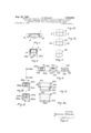
FIGS. 1, 2, 3, 3a, 3b, 3c, 4 show the various wrapping or packing stages of a product (consisting of an oval soap) which are accomplished according to the invention by a mechanical equipment illustrated in other figures;
FIG. 1 being a front elevation showing a first stage;
FIG. 2 being a side elevation looking at the left of FIG. 1;
FIG. 3 being a side elevation similar to FIG. 2, but showing a second stage;
FIG. 3a being an elevation looking at the left of FIG. 3;
FIG. 3b being a side elevation similar to FIG. 3, but showing a further stage; 7
FIG. 3:: being an elevation looking '-at the left of FIG. 3b;
FIG. 4 showing still further stages, viewed similarly to FIGS. 3 and 3b.
FIGS. 5, 5a and 5b show various possible wrapping shapes or packages obtainable with the same packing method and equipment;
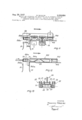
FIG. 6 ShOWs a plan view of a pick-up, centering and presetting assembly for three wrapping blanks and including the means for moving the three wrapping blanks towards the adjacent packing zone;
FIG. 7 shows the wrapping blanks already in the starting position of the packing cycle, when the product is carried on an elevator after being picked-up from a step conveyor; (FIGS. 6 and 7 are shown displaced with respect to each other; in practice member 13 in both figures are aligned);
FIG/7a shows such conveyor in elevation, comprising a conveyor belt with inner-toothing, which is externally provided with spacing members, for various product pieces, spaced from each other by a distance corresponding to the length of the feed step of thestep feeder;
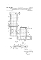
FIG. 8 shows in a plan view the top of an elevator, on which a piece of oval soap is arranged, whilst sideways of the elevator there is disposed a plane for the support of the product during its transfer from the belt conveyor to the elevator;
FIGS. 9 and 9a show a lateral view of the head of the elevator in the raised position during the first wrapping stage, during which the folding of the main front edges occurs, it being further noticeable from such figures that bending members are provided and a transposition of the elevator in a subsequent upward station position is also observed along the vertical trajectory of the elevator, whilst in the same figures there is represented a counterelevator, movable in the same direction as the underlying elevator;
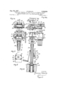
FIGS. 10 and 10a complete the preceding figures, showing the same mechanical assembly rotated by 90 and in which the elevator is provided with support and stem control means, feed means for the product being further shown at right-hand side of the figure, and in the intermediate zone, between the above-mentioned station positions being located stationary benders for an intermediate folding stage, in FIGURE 10a being further represented a detail pertaining to a folding stage of the reinforcing front edges, taking place at the upper station and the start of which implies a movement of the benders in both directions indicated by the arrows shown in the station zone, finally in the same figures being represented a subsequent folding stage of the wrapping blanks over a part of the lower face of the product; 7
FIG. 11 shows in side elevation a pick-up stage of the package from the elevator and a folding stage of another part of the wrapping blanks over the remaining part of the lower face of the product, said elevator not being shown herein for the sake of clearness, also because same may be noticed from other figures, the pick-up operation being in this case carried out by means of a comb;
FIG. 12 represents in elevation and in a closely analogous manner to the preceding figure, the same pick-up and completion stages of the wrapping operation, carried out with the use of a pusher, such both systems substantially attaining the same object, and finally FIG. 13 shows in elevation and in cross section a comb as per FIG. 11 while taking off a package from a corresponding not shown support, whilst the counter-plate cooperates with the afore-mentioned counter elevator and acts in such case as a guide for the product shown herein.
With reference to the drawing, in which the same members, are marked with the same reference numbers, a
4 V more detailed description will now be given of the equipment carrying out the packing method according to this invention and forming a typical wrapping shape with reinforced front ends of the package. From such detailed description the operation of the entire mechanical packing assembly may be deduced, besides the sequences of the various and successive wrapping stages of the product carried out without giving rise to impacts and dangerous stresses on the same.
Referring now to FIG. 1, a forming stage of the Wrapping of the product P will be noted therefrom consisting in the folding of the main edges 1a and 1b of the cardboard 1 over the front ends of the soap. In a second stage as per FIG. 2, in which the package is shown rotated by there occurs the downward folding of the side edges of the wrapping blanks. From the representations of both FIGURES 1 and 2 only a cardboard 1 (FIG. 1) and an outer wrapping 2 (FIG. 2 are shown, since for simplicity reasons an inner parchment paper wrapping up directly the product is omitted.
Passing now to FIG. 3 one may note the folding of the ends 201a and 301a of side edges or fiaps 201, 301 of the cardboard and respectively 202a, 302a of the edges 202, 302 of the outer wrapping blank over the edges 1a and 1b of the head parts, folded over in the first folding stage (FIG. 1). As is can be noted, the height of the end 201a and 301a of the side edges of the cardboard is substantially equal to the thickness of the product P to be wrapped, which packing when rotated by 90 will appear as in FIG. 3a.
FIG. 3b shows a subsequent folding of the lower part of the edges 201 and 202 of the cardboard and of the outer wrapping blank over the lower face of the product, and such folding is carried out by the machine at the same station point as per FIG. 3 as will become apparent hereinafter.
Furthermore FIG. 30 shows the shape of the package as per FIG. 3b rotated by 90, whilst in FIG. 4 there will be seen a succession of folding stages taking place during a continuous or intermittent motion of the package in which there occurs the folding of the edges 301 and 302 on the remaining part of the lower face of the product and subsequently the last folding of the double front edges 402, 502 of the outer wrapping on the said front ends of the package with gluing or sealing operation.
With reference now to FIG. 5 one may note different embodiment possibilities of the packing shape, accord ing to the packing method of this invention, regarding the formation of the front end of the package by the cardboard wrapping, this being the main member of the package itself.
Each front end can, in fact, be formed of a main edge or flap 4, which is first folded towards the corresponding front end of the product and of two edges or flaps 5 which are in turn folded over on the first one will be kept in the same plane with the ends abutting against each other and in contact.
The second case is closely analogous to the preceding case, the only difference consisting in having snipped the corners of edges 4a and 5a, 5b in order to substantially round off the corners of the package. In the third case, the head or front end is accomplished only by the main edge or limb 4b, which by folding over the head or front limb of the tubular body of the cardboard will build a considerably consistent structure.
Other embodiments analogous to the preceding ones orto the combinations of the preceding cases considered are possible, provided the reinforcement of the heads or front ends as proposed is made.
Reference is, now, made of the subsequent figures, of the drawing, wherein the mechanical packing assembly will be shown in a semi-schematical representation.
The packing machine is provided with a feeder 6 (FIGS. 7, 7a), constituted of a belt 7 with an internal toothing 8, subjected to the control of at least a pulley 9, provided with cylindrical cavities 9a corresponding to the belt teeth, with which, as already mentioned, suitable driving means cooperate so as to impart to the belt a constant step forward motion, such driving means being of normal use in, and packing machines. On the outer side of the belt there are likewise fastened the spacing members 10, spaced from one another by a distance corresponding to the length of the feed step. An intermittently controlled pusher 11 will displace during the dwell of the conveyor, the product P from a position A to a position B (FIG. 7), whilst the three wrapping blanks one of which is an internal parchment paper 12, the other is the intermediate cardboard 1 and the third is the outer wrapping or the outer printed paper 2 are brought to position B from position C by means of a transferring pick-up clamp 13. When the transfering pick-up clamp locks the three wrapping blanks in the position C, the scissors conventionally indicated by 14 (FIG. 6) enter into operation cutting said wrapping blanks along the axis D-Dl. A rubber coated roller device R causes the wrapping blanks to simultaneously move forward a constant length which will be little larger than the print step of the outer printed wrapping.
A photoelectrical device or the like, generally indicated by F1 (FIG. 6), permits to center the outer printed paper by imparting to the same if necessary eg a return motion whilst a second similar device F2 controls the return run of the shape-punched strip of the cardboard to ensure the step retention. Furthermore, the parchment paper is advanced in the desired measure without particular correction.
Position B, FIG. 7 corresponds to position B of FIG. 9. At point B (FIG. there is located a plate 15, which is flush with the level of the belt plane and provides support to the product during the sliding stage of the feeder towards an elevator, whilst a preferably rubber coated plate 16 (FIG. 8) is destined to support the product P in its center-of-gravity zone. Said plate 16 is mounted axially sliding over the internal zone in the head of an elevator with more members, which is well visible in its assembly from the FIGURES 8, 9, 10 and has the projections or fingers 17, which whilst raising have among other things the task of suitably centering the prouct. When the product, consisting in this case of convex oval soap, has been pushed from the terminal station of the compartment belt to position B, the tubular rod 18 carrying said arms 17 shifts from position M to position -N (FIG. 9) thus accomplishing a travel equal to the thickness of the item to be packed. Then the whole head of the elevator, namely said rod with fingers and the inner plate 16, accomplishes another travel being substantially equivalent to the length N-O as per FIG. 9. Thus the wrapping blanks which had been brought to the zone by the afore-mentioned pick-up clamp 13 (FIG. 6) are compressed by the ends of the projections 17 against the face of a counter-plate 19, springed on its support by means of springs 20, in such a way as to give -a slight load producing a small displacement S of the check rings 21, fast with the pins 22 constraining the counter-plate 19 with respect to the head 23 of the counter-elevator 24. For representation purposes, the above-mentioned numbers have been referred to the upper position B1. When the wrapping blanks are held up by the clamping action developed between said ends of the projections 17 and the upper counter-plate 19, the controlled clamp 13 opens and is displaced away to release the wrapping blanks.
In this stage enters into operation thefirst bender means 25, controlled by a lever 26 and a tie rod 27. The bender means are fulcrum-pivoted on the axes 28 and by means of toothed sectors 29, fast with the lever, are subjected to a simultaneous symmetrical action.
The benders 25 act on the ends of the limbs 1a, 1b (main front limbs), which are folded downwardly without touching the outer wrapping blank.
When the limbs 1a, 1b are practically vertical, the motion of the bender means 25 stops and there begins the raising of the product carried vertically by the elevator and counter-elevator.
It is to be noted that prior to the re-start of the raising motion, when the ends of the controlled benders 25 have reached their end stroke position, the hooks 30 (FIG. 9), springed and fast with the main part of the lower elevator, will have hooked up the limbs 1a, 1b holding them down in an approximately vertical position, the ends of the limbs being pushed by the ends of the bender means 25 holding them up during the stroke thereof.
In the raising stage the side edges or limbs of the wrappings are folded over as represented in FIG. 2 by direct action of the stationary longitudinal counter member 31 (FIG. 10).
Upon arrival of the product, entrained between the elevator means in the position B'l (FIG. 10 above), the four benders 32 simultaneously enter into operation, namely two benders at each end of the item to be packed.
Because of their action the wrappings fold over on the heads (see also FIG. 3) and the stresses exerted on such wrappings are taken by the metal edges of the projections 17, provided on the main member of the lower elevator, which ensures excellent and accurate foldings of the wrappings. At this stage of the packing cyclo, the benders have reached the position B2 and start up at once a small return motion to reduce pressure on the counter acting edges.
It should be noted that these benders act on both ends in a symmetrical and concomitant manner under a selfcentering control, since they are in fact, controlled by a toothed pinion 33 with stationary axis 34 engaging on the racks 35 provided on the support rods of the benders. The return run of the main part of the elevator including the four fingers 17 then starts and as soon as the way is open the displacement of the lower transverse bender 36 begins, which folds over the wrapping blanks by bringing them nearly into contact with the vertical wall of the central support plate 16. In this respect reference is made to FIG. 3b, in which the package for representation purposes is rotated with respect to FIG. 10, namely, Whilst in FIG. 10 said bender 36 actively displaces from right to left-hand side, in FIG. 3b the operated folding in the opposite sense is visible, and hence in the direction of the large arrow. Said support 16 is carried by the stem 216 and is maintained the upper position by the nose 37 (FIG. 10), acting against the counter means 38, fast with the rod 216. The nose 37 is fast with the limb 39 of a lever 40 carrying a stationary pin 41, on which a roller 42 is mounted.
Fast on the tubular stem 18 of the main elevator is a clamp 43 carrying a cam 44.
When the stem 18 has been lowered as desired, the profile 45 of the cam 44 abuts against the roller 42, causing the lever 40 to rotate around the axis 41 so much as to ensure displacement of the stopping nose 37 and to release in this manner the stopping tooth 32, which enable the plate 16 and the stem 216 to start a downward stroke, such member being drawn back by a spring 46 placed inside the hollow stem 18, said spring reacting upwardly against the inner top of such stem and downwardly against the rod 216.
When the lower elevator reaches the position N a double nose 47, fastened to the inner rod engages against a ring 48, springed by a spring 49.
The function of such membersis to deaden the stopping impact of the stem 216, the moving member being still subject to a residual speed.
The lower elevator proceeds further with its run down to the lower stroke end M, in which position the fingers 17 do not interfere with the passage of the product from position A to position B. It should be noted that upon release of the stopping nose 38 the rod 216 and related center plate 16 are drawn back with a certain force by the spring 40, applied to the downwardly moving stem. The spring accelerates the mass which a moment earlier was without motion. In order to avoid a disturbing contact impact between the main plate stem 216 and the centering support body, a pneumatic brake is provided, consisting of an annular air chamber, not shown but easily deduceable and defined by the center part 316 of the plate and by the stem 216 and further completed with a circular housing provided on the hollow head of the elevator.
The diameter of the piston and housing is bored in such 'a way as to leave a small clearance such as to stop the exit of the air stored therein thus creating the desired braking back-pressure. Anyhow, on the bottom of the air tube is placed a rubber washer 50, adapted to keep up the position of mutual distance of the parts as desired thereby also contributing to the dampening action.
Once the stroke of the longitudinal bender 36, which operates the folding as per FIG. 3b, is terminated there takes place the intervention of the projections 51, FIG. 9, separately controlled and cooperating with said bender 36. Such projections 51 extend over the center while sustaining the product at the moment in which the plate 16 be- :gins its downward return motion. At this stage there takes place also the start of a translatory motion of the package to operate the folding of the remaining side edges or limbs on the lower face of the product thanks to a stationary'counter-profile 52.
The package may be directly moved by a comb member 53 (FIGS. 11, 13), subjected to an intermittent motion driving means of known type, or by a controlled pusher 54 (FIG. 12). In any case, the package is caused to travel and is guided within a guide way 55 or 555, sideways of which are provided for example the benders 56, 57 for the folding of the double limbs 402, 502 of the outer wrapping blank over the front ends (see also FIG. 4) and a gluing device 58, or one may provide helicoidal contour members 59, furthermore the package may be closed by means of a heat-sealing system.
The aforesaid folding and gluing systems of the double head limbs of the outer wrapping may be considered as intuitive, since they contemplate the adoption of widely used devices.
The kinematic limbs and motion of the above-described mechanical assembly, may be easily deduced from the above description by those skilled in the art.
This invention thus attains the desired objects whilst being subject to changes and modifications, falling Within the scope of the invention.
For example the feed system of the Wrapping materials may be such as to deliver already cut paper blanks for the intermediate cardboard, the outer wrapping and/ or inner parchment paper as well.
- I claim: I s i Y A- packing machine for wrapping bodies offa delicate nature and of a non-parallelepiped shape in a plurality of wrappings, comprising means for feeding the wrapping material in a pick-up station, means for picking up the wrappings from the pick-up station and transferring them to a wrapping station, belt conveyor means for feeding the body to be packaged towards the wrapping station, said belt conveyor means having spacing members defining compartments for receiving on said belt conveyor single bodies to be packaged, pusher means to push said body from said belt conveyor towards the wrapping station, and bender means for folding the wrappings over said body, wherein the improvement comprises near said wrap? ping station (B, B hollow tubular member (18) below said wrapping station (B, B said tubular member having four spaced apart fingers (17 fixed thereto and upwardly projecting therefrom beyond the upper end of the tubular member, said fingers being arranged in positions corresponding to the upper corners of thepackage to be formed and having edges corresponding to the edges of the corners of the package to be formed, said fingers being adapted to support the wrappings and to allow the wrapping to be folded over the edges of the corner shape defined by said fingers, a stem (216) coaxial with and slidably arranged within said tubular member (18), said stem carrying a supporting plate (16) at the upper end thereof, said supporting plate (16) projecting normally beyond the upper end of said tubular member (18) and being arranged in the vertical axis of symmetry of said corners defined by said fingers (17) to support the body to be wrapped in the zone of its center of gravity line, and means for imparting a reciprocating vertical movement to said tubular member (18).-
References Cited UNITED STATES PATENTS 2,050,713 8/1936 Malocsay 53-218 X 2,208,776 7/ 1940 Sandberg 53-223 X 2,215,036 9/1940 Hartman 53-223 X 2,592,726 4/1952 Palmer et al 53-210 2,611,224 9/1952 Jensen 53-51 TRAVIS S. MCGEHEE, Primary Examiner.
FRANK E. BAILEY, Examiner. I
L. S. BOUCHARD, Assistant Examiner.
an elevator member having a vertical
Applications Claiming Priority (1)
| Application Number | Priority Date | Filing Date | Title |
|---|---|---|---|
| IT950763 | 1963-05-07 |
Publications (1)
| Publication Number | Publication Date |
|---|---|
| US3338024A true US3338024A (en) | 1967-08-29 |
Family
ID=11131203
Family Applications (1)
| Application Number | Title | Priority Date | Filing Date |
|---|---|---|---|
| US365534A Expired - Lifetime US3338024A (en) | 1963-05-07 | 1964-05-06 | Method and apparatus for executing in an automatic packing machine a container wrapping, adapted to wrap delicate products having also a non-parallelepiped shape |
Country Status (2)
| Country | Link |
|---|---|
| US (1) | US3338024A (en) |
| DE (1) | DE1461761A1 (en) |
Cited By (4)
| Publication number | Priority date | Publication date | Assignee | Title |
|---|---|---|---|---|
| US5819506A (en) * | 1995-11-10 | 1998-10-13 | Carle & Montanari S.P.A. | Method and apparatus for closing the edges of wrapping material |
| US20060201115A1 (en) * | 2003-05-23 | 2006-09-14 | Colgate-Palmolive Company | Method of wrapping products |
| US20060201114A1 (en) * | 2003-08-06 | 2006-09-14 | Maurizio Oleandri | Method and device for wrapping products |
| WO2008087510A3 (en) * | 2007-01-19 | 2008-11-13 | Rc S P A | Device for the formation of a product package |
Families Citing this family (2)
| Publication number | Priority date | Publication date | Assignee | Title |
|---|---|---|---|---|
| IT984891B (en) * | 1973-05-09 | 1974-11-20 | Gd Soc In Accomandita Sempli C | HIGH SPEED INTER SENDER OPERATING CYCLE MACHINE FOR WRAPPING SOAP PIECES AND OTHER SIMILAR PRODUCTS |
| IT1290689B1 (en) * | 1997-02-20 | 1998-12-10 | Gd Spa | METHOD AND DEVICE FOR PACKAGING GROUPS OF PRODUCTS, PARTICULARLY PACKAGES OF CIGARETTES. |
Citations (5)
| Publication number | Priority date | Publication date | Assignee | Title |
|---|---|---|---|---|
| US2050713A (en) * | 1932-02-03 | 1936-08-11 | Cons Internat Corp | Wrapping and banding machine |
| US2208776A (en) * | 1937-12-11 | 1940-07-23 | Automatic Packaging Machinery | Wrapping machine |
| US2215036A (en) * | 1937-07-31 | 1940-09-17 | Hartman William Walter | Combination bread slicing and wrapping machine |
| US2592726A (en) * | 1948-11-24 | 1952-04-15 | Bettendorf Co | Wrapping machine |
| US2611224A (en) * | 1947-07-01 | 1952-09-23 | American Mach & Foundry | Registration device for wrapping machines |
-
1964
- 1964-05-06 US US365534A patent/US3338024A/en not_active Expired - Lifetime
- 1964-05-06 DE DE19641461761 patent/DE1461761A1/en active Pending
Patent Citations (5)
| Publication number | Priority date | Publication date | Assignee | Title |
|---|---|---|---|---|
| US2050713A (en) * | 1932-02-03 | 1936-08-11 | Cons Internat Corp | Wrapping and banding machine |
| US2215036A (en) * | 1937-07-31 | 1940-09-17 | Hartman William Walter | Combination bread slicing and wrapping machine |
| US2208776A (en) * | 1937-12-11 | 1940-07-23 | Automatic Packaging Machinery | Wrapping machine |
| US2611224A (en) * | 1947-07-01 | 1952-09-23 | American Mach & Foundry | Registration device for wrapping machines |
| US2592726A (en) * | 1948-11-24 | 1952-04-15 | Bettendorf Co | Wrapping machine |
Cited By (5)
| Publication number | Priority date | Publication date | Assignee | Title |
|---|---|---|---|---|
| US5819506A (en) * | 1995-11-10 | 1998-10-13 | Carle & Montanari S.P.A. | Method and apparatus for closing the edges of wrapping material |
| US20060201115A1 (en) * | 2003-05-23 | 2006-09-14 | Colgate-Palmolive Company | Method of wrapping products |
| US20060201114A1 (en) * | 2003-08-06 | 2006-09-14 | Maurizio Oleandri | Method and device for wrapping products |
| US7302786B2 (en) * | 2003-08-06 | 2007-12-04 | Azionaria Costruzioni Macchine Automatiche A.C.M.A. S.P.A. | Method and device for wrapping products |
| WO2008087510A3 (en) * | 2007-01-19 | 2008-11-13 | Rc S P A | Device for the formation of a product package |
Also Published As
| Publication number | Publication date |
|---|---|
| DE1461761A1 (en) | 1969-03-06 |
Similar Documents
| Publication | Publication Date | Title |
|---|---|---|
| US4183194A (en) | Apparatus for producing a wrapper closed by a weld seam for balls of yarn | |
| US2960808A (en) | Machine and method for packaging food products | |
| US3919827A (en) | Method and apparatus for packaging large size bags in cartons | |
| US3418893A (en) | Carton feeding and erecting apparatus | |
| US3739545A (en) | Method and apparatus for packaging articles | |
| US3432986A (en) | Packaging machine of the form-and-fill type | |
| US3338024A (en) | Method and apparatus for executing in an automatic packing machine a container wrapping, adapted to wrap delicate products having also a non-parallelepiped shape | |
| US1816085A (en) | Wrapping machine and process | |
| US1045391A (en) | Package-inserting machine. | |
| US2728177A (en) | Carton packing machine | |
| US3097463A (en) | Packaging machine | |
| US1295951A (en) | Packaging-machine. | |
| DK141497B (en) | End-field closure machine on a tubular carrier board. | |
| US3702524A (en) | Case loader with article inverting mechanism | |
| US2848856A (en) | Lid forming machine | |
| US1219427A (en) | Carton-upsetting device. | |
| US1739619A (en) | Apparatus for setting up cartons | |
| US3063209A (en) | Packaging machine and method | |
| US2010275A (en) | Wrapping machine | |
| US2137656A (en) | Wrapping machine | |
| US2941340A (en) | Carton-formiong and closing means and method | |
| US3611675A (en) | Apparatus for wrapping articles | |
| US3299610A (en) | Apparatus for filling sleeve package | |
| GB1025270A (en) | Improvements in wrapping machines | |
| US2050715A (en) | Banding and wrapping machine |