US3337014A - Ratchet wrench - Google Patents
Ratchet wrench Download PDFInfo
- Publication number
- US3337014A US3337014A US498342A US49834265A US3337014A US 3337014 A US3337014 A US 3337014A US 498342 A US498342 A US 498342A US 49834265 A US49834265 A US 49834265A US 3337014 A US3337014 A US 3337014A
- Authority
- US
- United States
- Prior art keywords
- teeth
- pawl
- head
- ratchet
- driven member
- Prior art date
- Legal status (The legal status is an assumption and is not a legal conclusion. Google has not performed a legal analysis and makes no representation as to the accuracy of the status listed.)
- Expired - Lifetime
Links
Images
Classifications
-
- B—PERFORMING OPERATIONS; TRANSPORTING
- B25—HAND TOOLS; PORTABLE POWER-DRIVEN TOOLS; MANIPULATORS
- B25B—TOOLS OR BENCH DEVICES NOT OTHERWISE PROVIDED FOR, FOR FASTENING, CONNECTING, DISENGAGING, OR HOLDING
- B25B13/00—Spanners; Wrenches
- B25B13/46—Spanners; Wrenches of the ratchet type, for providing a free return stroke of the handle
- B25B13/461—Spanners; Wrenches of the ratchet type, for providing a free return stroke of the handle with concentric driving and driven member
- B25B13/462—Spanners; Wrenches of the ratchet type, for providing a free return stroke of the handle with concentric driving and driven member the ratchet parts engaging in a direction radial to the tool operating axis
- B25B13/465—Spanners; Wrenches of the ratchet type, for providing a free return stroke of the handle with concentric driving and driven member the ratchet parts engaging in a direction radial to the tool operating axis a pawl engaging an internally toothed ring
-
- Y—GENERAL TAGGING OF NEW TECHNOLOGICAL DEVELOPMENTS; GENERAL TAGGING OF CROSS-SECTIONAL TECHNOLOGIES SPANNING OVER SEVERAL SECTIONS OF THE IPC; TECHNICAL SUBJECTS COVERED BY FORMER USPC CROSS-REFERENCE ART COLLECTIONS [XRACs] AND DIGESTS
- Y10—TECHNICAL SUBJECTS COVERED BY FORMER USPC
- Y10S—TECHNICAL SUBJECTS COVERED BY FORMER USPC CROSS-REFERENCE ART COLLECTIONS [XRACs] AND DIGESTS
- Y10S81/00—Tools
- Y10S81/05—Wrench scales and indicia
Definitions
- This invention relates to ratchet devices and particular- Iy ratchet wrenches of the reversible type having a reversing mechanism located in a cylindrical head of the wrench.
- One object of the invention is to provide an improved means for actuating the reversing mechanism of a ratchet wrench of the type shown in Rueb Patent No. 2,232,477, my type of actuating device being so designed that frictional forces are encountered as between a reversible ratchet mechanism and a manual actuator therefor which prevents the reversible actuating mechanism from accidentally releasing during operation of the wrench.
- Another object is to provide means for actuating a reversible ratchet mechanism wherein a spring pressed plunger carried by a stub shaft coacts with a cam surface of a ratchet pawl, which means comprising a cross bar on one end of the stub shaft and a slot in a manually rotatable disc coacting therewith in such manner that.
- any tendency for the ratchet mechanism to slip out of operative position is resisted by the force of frictional engagement as between the cross bar and a recess of the disc greater than the force of the ratchet mechanism itself during operation to drift out of operative position.
- a further object is to provide means for reversing the ratchet mechanism of a wrench which involves a minimum of change in parts from those disclosed in the Rueb patent above designated.
- my invention consists in the construction, arrangement and combination of the various parts of my ratchet wrench, whereby the objects above contemplated are attained, as hereinafter more fully set forth, pointed out in my claims and illustrated in detail on the accompanying drawing, wherein:
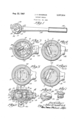
- FIG. 1 is a'plan view of a ratchet wrench embodying my novel ratchet device
- FIG. 2 is an enlarged vertical sectional view on the line 2--2 of FIG. l;
- FIGS. 3 and 4 are horizontal sectional views on the lines 3-3 and 4-4, respectively, of FIG. 2 and show the parts in position for clockwise rotation of work-engaging means forming part of the ratchet wrench, a line 2-2 across both figures indicating where, in respect to them, FIG. 2 is taken;
- FIG. 5 is a sectional view similar to FIG. 4 showing the ratchet mechanism being adjusted from clockwise to counter-clockwise rotation;
- FIG. 6 is a view similar to FIGS. 4 and 5 showing the ratchet mechanism adjusted for counter-clockwise rotation of the work-engaging means
- FIG. 7 is a perspective view of a pawl actuating plunger carrying stub shaft and a cross bar forming part thereof, and
- FIG. 8 is a perspective View of a disc for actuating the stub shaft and showing a slot-like recess which coacts with the cross bar of the stub shaft.
- the accompanying drawing I have used the reference numeral to indicate a cylindrical head of a ratchet wrench, and 12 a lever extending therefrom and terminating in a handle 14.
- the head 10 is provided with internal peripheral ratchet teeth 15 as shown in FIGS. 2 and 3 and is provided with an inturned ange 16 at the top as shown in FIG. 2.
- a driven member 18 Rotatable within the head 10 is a driven member 18 having an annular flange 19 at its upper end and a retainer ring groove 21 adjacent its lower end.
- the driven member 18 is provided with a work-engaging means 20 in the form of a shank with which various sizes ⁇ of sockets may be associated in the usual manner of socket wrench sets.
- a retainer ring 23 is provided to retain the driven member 18 in the head 10.
- the driven member 18 has a transverse opening or slot 22 in which a double-ended pawl 26 is operable.
- a pivot 24 is provided for the pawl and the ends of the pawl are provided with ratchet teeth 27 and 27a to coact with the internal peripheral ratchet teeth 15 of the head 10 as will hereinafter appear.
- the pawl is also provided with a cam surface 29.
- a stub shaft 28 is rotatably mounted in the driven member 18 and is positioned olf center with respect to the axis of rotation of the driven member for purposes set forth in the Rueb patent. It is provided with a pawl actuating plunger 38 slidably mounted in a transverse hole of the stub shaft and having its outer end engaging the cam surface 29 as shown in FIG. 3. A spring 40 biases the plunger toward the pawl. The spring and plunger serve to reverse the position of the pawl and thus the action of the ratchet wrench.
- the foregoing described mechanism is common to both the present disclosure and the Rueb patent.
- My specific improvement consists in a means for actuating the stub shaft to rotate it with respect to the pawl 26 and thereby reverse the ratchet action.
- My contribution to the prior art as represented by the Rueb patent comprises a cross bar 30 formed on or secured to one end of the stub shaft 28, a disc 32 rotatably mounted and having its axis of rotation coincident with the axis of rotation of the driven member 18, and a means of coaction between the disc 32 and the cross bar 30 in the form of a slot-like recess 34 receiving the cross bar as shown in FIGS. 2 and 4 to 6, inclusive.
- the disc 32 is provided with an external flange-like finger piece 36 to facilitate rotation of the disc.
- ratchet device having a cylindrical head provided with internal peripheral ratchet teeth, a driven member rotatably mounted in said head and having work-engaging means, said driven member having a transverse opening therein, a pivot mounted in said driven member and extending through said opening, a doubleended pawl carried by said pivot and having ratchet teeth adapted to coact with said teeth in said head for reversing the movement of said driven member, a stub shaft mounted in said driven member adjacent said pawl and having its axis off center from the axis of said head, a plunger slidably mounted in a transverse hole in said stub shaft and having its outer end engaging with a cam surface of said pawl, a spring biasing said plunger toward said pawl, said spring and plunger serving to reverse the position of said pawl and also to hold the teeth thereof in ratcheting engagement with the teeth of said head; means for actuating said stub shaft to reverse the action of said ratchet device comprising
Landscapes
- Engineering & Computer Science (AREA)
- Mechanical Engineering (AREA)
- Details Of Spanners, Wrenches, And Screw Drivers And Accessories (AREA)
Description
J. A. SANDRICK RATCHET WRENCH Aug. 22, i967 Filed Oct. 20, 1965 UnitedStates Patent O 3,337,014 RATCHET WRENCH John A. Sandrick, 8636s. Wolcott, Chicago, Ill. 60620 Filed Oct. 20, 1965, Ser. No. 498,342 4 Claims. (Cl. 192-43.1)
This invention relates to ratchet devices and particular- Iy ratchet wrenches of the reversible type having a reversing mechanism located in a cylindrical head of the wrench.
One object of the invention is to provide an improved means for actuating the reversing mechanism of a ratchet wrench of the type shown in Rueb Patent No. 2,232,477, my type of actuating device being so designed that frictional forces are encountered as between a reversible ratchet mechanism and a manual actuator therefor which prevents the reversible actuating mechanism from accidentally releasing during operation of the wrench.
Another object is to provide means for actuating a reversible ratchet mechanism wherein a spring pressed plunger carried by a stub shaft coacts with a cam surface of a ratchet pawl, which means comprising a cross bar on one end of the stub shaft and a slot in a manually rotatable disc coacting therewith in such manner that.
any tendency for the ratchet mechanism to slip out of operative position is resisted by the force of frictional engagement as between the cross bar and a recess of the disc greater than the force of the ratchet mechanism itself during operation to drift out of operative position.
A further object is to provide means for reversing the ratchet mechanism of a wrench which involves a minimum of change in parts from those disclosed in the Rueb patent above designated.
With these and other objects in view, my invention consists in the construction, arrangement and combination of the various parts of my ratchet wrench, whereby the objects above contemplated are attained, as hereinafter more fully set forth, pointed out in my claims and illustrated in detail on the accompanying drawing, wherein:
FIG. 1 is a'plan view of a ratchet wrench embodying my novel ratchet device;
FIG. 2 is an enlarged vertical sectional view on the line 2--2 of FIG. l;
FIGS. 3 and 4 are horizontal sectional views on the lines 3-3 and 4-4, respectively, of FIG. 2 and show the parts in position for clockwise rotation of work-engaging means forming part of the ratchet wrench, a line 2-2 across both figures indicating where, in respect to them, FIG. 2 is taken;
FIG. 5 is a sectional view similar to FIG. 4 showing the ratchet mechanism being adjusted from clockwise to counter-clockwise rotation;
FIG. 6 is a view similar to FIGS. 4 and 5 showing the ratchet mechanism adjusted for counter-clockwise rotation of the work-engaging means;
FIG. 7 is a perspective view of a pawl actuating plunger carrying stub shaft and a cross bar forming part thereof, and
FIG. 8 is a perspective View of a disc for actuating the stub shaft and showing a slot-like recess which coacts with the cross bar of the stub shaft.
O11 the accompanying drawing I have used the reference numeral to indicate a cylindrical head of a ratchet wrench, and 12 a lever extending therefrom and terminating in a handle 14. The head 10 is provided with internal peripheral ratchet teeth 15 as shown in FIGS. 2 and 3 and is provided with an inturned ange 16 at the top as shown in FIG. 2.
Rotatable within the head 10 is a driven member 18 having an annular flange 19 at its upper end and a retainer ring groove 21 adjacent its lower end. The driven member 18 is provided with a work-engaging means 20 in the form of a shank with which various sizes `of sockets may be associated in the usual manner of socket wrench sets. To retain the driven member 18 in the head 10, a retainer ring 23 is provided.
The driven member 18 has a transverse opening or slot 22 in which a double-ended pawl 26 is operable. A pivot 24 is provided for the pawl and the ends of the pawl are provided with ratchet teeth 27 and 27a to coact with the internal peripheral ratchet teeth 15 of the head 10 as will hereinafter appear. The pawl is also provided with a cam surface 29.
A stub shaft 28 is rotatably mounted in the driven member 18 and is positioned olf center with respect to the axis of rotation of the driven member for purposes set forth in the Rueb patent. It is provided with a pawl actuating plunger 38 slidably mounted in a transverse hole of the stub shaft and having its outer end engaging the cam surface 29 as shown in FIG. 3. A spring 40 biases the plunger toward the pawl. The spring and plunger serve to reverse the position of the pawl and thus the action of the ratchet wrench. The foregoing described mechanism is common to both the present disclosure and the Rueb patent.
My specific improvement consists in a means for actuating the stub shaft to rotate it with respect to the pawl 26 and thereby reverse the ratchet action. My contribution to the prior art as represented by the Rueb patent comprises a cross bar 30 formed on or secured to one end of the stub shaft 28, a disc 32 rotatably mounted and having its axis of rotation coincident with the axis of rotation of the driven member 18, and a means of coaction between the disc 32 and the cross bar 30 in the form of a slot-like recess 34 receiving the cross bar as shown in FIGS. 2 and 4 to 6, inclusive.
The disc 32 is provided with an external flange-like finger piece 36 to facilitate rotation of the disc.
In a ratchet wrench made according to the Rueb patent, during operation there is a tendency for the ratchet mechanism when adjusted to either clockwise or counterclockwise rotation, to drift out of these adjusted positions and the teeth of the pawl to disengage from the teeth of the head whereupon the wrench is inoperative until the ratchet mechanism is readjusted to the clockwise or counter-clockwise position desired. This tendency comes about by reason of the combined action of the spring pressed plunger 38 against the cam surface 29 and the movement of the pawl 26 as it ratchets past the teeth 15 in the retrograde movement of the lever 12 during the oscillations of the lever for tightening or loosening a nut or bolt.
In my improvement, when the wrench is adjusted for clockwise rotation as in FIGS. 3 and 4, the disc 32 has been turned in the direction of the arrow a by means of the linger piece 36 which resulted in the cross bar 30 being also turned in that direction (arrow e) until stopped by engagement of its upper left corner (FIG. 4) with the inner surface of the flange 19. This adjustment also would have rotated the stub shaft 28 and the plunger 38 carried thereby in the direction of the arrow b in FIG. 3. Upon clockwise rotation of the lever 12 according to the arrow c in FIG. 3, the driven member 18 will likewise be rotated clockwise according to the arrow d. When the lever 12 is moved counter to the arrow c, the teeth 15 of the head 10 will ratchet past the teeth 27 of the pawl 26 and this has the'further tendency of rotating the stub shaft 28 in the direction of the arrow b.Also when the lever 12 is moved in the direction of the arrow c, the cross bar 30 in FIG. 4 will tend to be rotated counter to the arrow e so that its upper right corner is in frictional engagement at point x in FIG. 4 with a side of the recess 34. Accordingly, the cross bar 30 is tending to rotate the disc 32 in the undesirable direction (counter to arrow a) instead of tending to stay in the counter-clockwise position. The friction at point x, however, is much greater than this tendency to rotate the disc 32 in the undesirable direction. Therefore, the ratchet mechanism does not become inoperative during ratcheting operation of the wrench.
When it is desirable to adjust the wrench for counterclockwise rather than clockwise rotation, the iinger piece 36 is grasped and rotated clockwise (arrow f in FIG. 5) and accordingly rotates the cross bar 30 clockwise. Finally the position of FIG. 6 is reached with the lower left corner of the cross bar stopped by the inner surface of the annular flange 19. The handle 14 of the wrench may now be oscillated and the work engaging means 20 will rotate the work counter-clockwise whereas the wrench will ratchet upon movement in the clockwise direction. The tendency of the ratchet mechanism to slip out of ratchet-tooth engagement during operation will operate in FIG. 6 in the reverse fashion described in connection with FIG. 4 and tend to keep the wrench adjusted for counter-clockwise operation.
From the foregoing specification it will be obvious that I have provided an improvement in a ratchet device which insures proper operation of the ratchet mechanism during operation of the wrench without any tendency for the mechanism to release. This is desirable in connection with the operation of a ratchet wrench in order to provide reliability of the ratcheting action and to avoid any possibility of the mechanism mulfunctioning.
Some changes may be made in the construction and arrangement of the parts of my ratchet wrench without departing from the real spirit and purpose of my invention, and it is my intention to cover by my claims any modied forms of structure or use of mechanical equivalents which may reasonably be included within their scope.
I claim as my invention:
1. In that type of ratchet device having a cylindrical head provided with internal peripheral ratchet teeth, a driven member rotatably mounted in said head and having work-engaging means, said driven member having a transverse opening therein, a pivot mounted in said driven member and extending through said opening, a doubleended pawl carried by said pivot and having ratchet teeth adapted to coact with said teeth in said head for reversing the movement of said driven member, a stub shaft mounted in said driven member adjacent said pawl and having its axis off center from the axis of said head, a plunger slidably mounted in a transverse hole in said stub shaft and having its outer end engaging with a cam surface of said pawl, a spring biasing said plunger toward said pawl, said spring and plunger serving to reverse the position of said pawl and also to hold the teeth thereof in ratcheting engagement with the teeth of said head; means for actuating said stub shaft to reverse the action of said ratchet device comprising a cross bar on one end of said stub shaft, a manually rotatable disc carried by said cylindrical head and rotatable about the axis thereof, said disc having an oif lcenter recess for receiving said cross bar, the off center position `of said cross bar and recess providing a sliding friction type of coaction between the two with such friction being operable to prevent accidental release of the teeth of said double-ended pawl from said teeth of said head as a result of the bias of said plunger against said cam surface upon operation of said ratchet device.
2. Means of the character claimed in claim 1 wherein said driven member has a peripheral flange Within which said disc rotates, the outer ends of said recess terminating at said ange and the ends of said cross bar being engageable with said flange to limit the opposite reversing positions of said stub shaft.
3. Means of the character claimed in claim 1 wherein said disc is provided with an external iinger piece for turning the same.
4. Means of the character claimed in claim 2 wherein said cylindrical head has an inwardly extending flange at one end and said disc has its periphery confined by said annular ange and being confined against axial dislocation from said head by said inwardly extending ange thereof.
References Cited UNITED STATES PATENTS 1/1940 Rueb 192--43.1 2/1941 Rueb l92-43.1
Claims (1)
1. IN THAT TYPE OF RATCHET DEVICE HAVING A CYLINDRICAL HEAD PROVIDED WITH INTERNAL PERIPHERAL RATCHET TEETH, A DRIVEN MEMBER ROTATABLY MOUNTED IN SAID HEAD AND HAVING WORK-ENGAGING MEANS, SAID DRIVEN MEMBER HAVING A TRANSVERSE OPENING THEREIN, A PIVOT MOUNTED IN SAID DRIVEN MEMBER AND EXTENDING THROUGH SAID OPENING, A DOUBLEENDED PAWL CARRIED BY SAID PIVOT AND HAVING RATCHET TEETH ADAPTED TO COACT WITH SAID TEETH IN SAID HEAD FOR REVERSING THE MOVEMENT OF SAID DRIVEN MEMBER, A STUB SHAFT MOUNTED IN SAID DRIVEN MEMBER ADJACENT SAID PAWL AND HAVING ITS AXIS OFF CENTER FROM THE AXIS OF SAID HEAD, A PLUNGER SLIDABLY MOUNTED IN A TRANSVERSE HOLE IN SAID STUB SHAFT AND HAVING ITS OUTER END ENGAGING WITH A CAM SURFACE OF SAID PAWL, A SPRING BIASING SAID PLUNGER TOWARD SAID PAWL, SAID SPRING AND PLUNGER SERVING TO REVERSE THE POSITION OF SAID PAWL AND ALSO TO HOLD THE TEETH THEREOF IN RATCHETING ENGAGEMENT WITH THE TEETH OF SAID HEAD; MEANS FOR ACTUATING SAID STUB SHAFT TO REVERSE THE ACTION OF SAID RATCHET DEVICE COMPRISING A CROSS BAR ON ONE END OF SAID STUB SHAFT, A MANUALLY ROTATABLE DISC CARRIED BY SAID CYLINDRICAL HEAD AND ROTATABLE ABOUT THE AXIS THEREOF, SAID DISC HAVING AN OFF CENTER POSITION OF SAID CROSS BAR AND CROSS BAR, THE OFF CENTER POSITION OF SAID CROSS BAR AND RECESS PROVIDING A SLIDING FRICTION TYPE OF COACTION BETWEEN THE TWO WITH SUCH FRICTION BEING OPERABLE TO PREVENT ACCIDENTAL RELEASE OF THE TEETH OF SAID DOUBLE-ENDED PAWL FROM SAID TEETH OF SAID HEAD AS A RESULT OF THE BIAS OF SAID PLUNGER AGAINST SAID CAM SURFACE UPON OPERATION OF SAID RATCHET DEVICE.
Priority Applications (1)
| Application Number | Priority Date | Filing Date | Title |
|---|---|---|---|
| US498342A US3337014A (en) | 1965-10-20 | 1965-10-20 | Ratchet wrench |
Applications Claiming Priority (1)
| Application Number | Priority Date | Filing Date | Title |
|---|---|---|---|
| US498342A US3337014A (en) | 1965-10-20 | 1965-10-20 | Ratchet wrench |
Publications (1)
| Publication Number | Publication Date |
|---|---|
| US3337014A true US3337014A (en) | 1967-08-22 |
Family
ID=23980675
Family Applications (1)
| Application Number | Title | Priority Date | Filing Date |
|---|---|---|---|
| US498342A Expired - Lifetime US3337014A (en) | 1965-10-20 | 1965-10-20 | Ratchet wrench |
Country Status (1)
| Country | Link |
|---|---|
| US (1) | US3337014A (en) |
Cited By (44)
| Publication number | Priority date | Publication date | Assignee | Title |
|---|---|---|---|---|
| EP0032423A1 (en) * | 1980-01-11 | 1981-07-22 | Kirk Koo Chow | Reversible ratchet drive |
| US5495783A (en) * | 1994-07-08 | 1996-03-05 | Snap-On Incorporated | Reversible ratchet wrench with direction indicia |
| FR2745515A1 (en) * | 1996-03-01 | 1997-09-05 | Facom | Bi-directional rotary drive tool |
| EP0798083A1 (en) * | 1994-10-12 | 1997-10-01 | Chang Chuan Lee | Reversible ratchet wrench and reversible ratchet mechanism thereof |
| US6138532A (en) * | 1999-05-14 | 2000-10-31 | Mccann; Frank | Wrench having driving direction indicator |
| US6230591B1 (en) | 1999-07-30 | 2001-05-15 | Hand Tool Design Corporation | Reversible ratcheting tool with improved gear wheel/pawl engagement |
| US6282992B1 (en) * | 2000-02-03 | 2001-09-04 | Bobby Hu | Biasing arrangement for a pawl of a reversible ratchet-type wrench |
| US6370993B1 (en) * | 1999-07-13 | 2002-04-16 | Martin H. Pitstick | Spring loaded self actuating impact driver |
| US6431031B1 (en) | 1999-12-16 | 2002-08-13 | Bobby Hu | Reversible ratcheting tool with a smaller head |
| US6450066B1 (en) | 2001-10-19 | 2002-09-17 | Bobby Hu | Head of a wrench handle |
| US6453779B2 (en) | 2000-07-21 | 2002-09-24 | Bobby Hu | Positioning device for a switch member of a reversible ratchet-type wrench |
| US6457389B1 (en) * | 2000-08-22 | 2002-10-01 | Bobby Hu | Switching arrangement for a reversible ratchet type wrench |
| US6457387B1 (en) | 2000-01-11 | 2002-10-01 | Bobby Hu | Reversible ratcheting tool with a smaller head and improved driving torque |
| US6520051B1 (en) | 2001-12-27 | 2003-02-18 | Bobby Hu | Head of a wrench handle |
| US6539825B1 (en) | 2001-09-20 | 2003-04-01 | Yen-Wen Lin | Single direction ratcheting wrench with stuck prevention and ratcheting direction indication |
| US20030075024A1 (en) * | 2001-10-23 | 2003-04-24 | Hsien-Chung Tuan-Mu | Single-direction operation type ratchet wrench structure |
| US6568299B2 (en) | 1999-12-16 | 2003-05-27 | Bobby Hu | Reversible ratcheting tool with a smaller head |
| USD477756S1 (en) | 2001-07-23 | 2003-07-29 | Hand Tools Design Corporation | Tool and reversing lever |
| US6644148B2 (en) | 2002-02-08 | 2003-11-11 | Bobby Hu | Reversible ratchet-type wrench |
| US6647832B2 (en) | 2001-07-27 | 2003-11-18 | Bobby Hu | Wrench having two rigid supporting areas for a pawl |
| US6666112B2 (en) | 2000-09-01 | 2003-12-23 | Bobby Hu | Switching arrangement for a reversible ratchet type wrench |
| US6666117B2 (en) | 2001-07-13 | 2003-12-23 | Bobby Hu | Wrench with a fixed maximum operational torque |
| USD484374S1 (en) | 2001-07-23 | 2003-12-30 | Hand Tools Design Corporation | Tool reversing lever |
| US6722234B2 (en) | 2001-05-14 | 2004-04-20 | Bobby Hu | Easy-to-operate and easy-to-assemble ratcheting-type wrench |
| US6732614B2 (en) | 2001-02-19 | 2004-05-11 | Bobby Hu | Easy-to-manufacture and easy-to-assemble ratcheting-type wrench |
| US6745647B2 (en) | 2000-11-29 | 2004-06-08 | Mei-Chen Wang | Wrench having a universal-joint ratchet wheel |
| US6758641B2 (en) | 2001-07-13 | 2004-07-06 | Bobby Hu | Method for manufacturing a ratchet type ring spanner having a larger cavity for receiving a larger pawl |
| USD496237S1 (en) | 2002-04-18 | 2004-09-21 | Easco Hand Tools, Inc. | Ratchet release button |
| US6807882B2 (en) | 2001-05-07 | 2004-10-26 | Bobby Hu | Wrench with a simplified structure |
| USD505308S1 (en) * | 2001-07-23 | 2005-05-24 | Hand Tools Design Corporation | Tool reversing lever |
| US20050120833A1 (en) * | 2003-12-04 | 2005-06-09 | Chih-Min Chang | Ratchet wrench having device for indication of wrench size and turning orientation |
| USD509717S1 (en) | 2002-04-18 | 2005-09-20 | Easco Hand Tools, Inc. | Ratchet wrench body |
| US6945141B2 (en) | 2002-04-22 | 2005-09-20 | Bobby Hu | Reversible ratchet type wrench |
| US20050218387A1 (en) * | 2004-03-30 | 2005-10-06 | Burns Bros., Inc. | Load binder with indicator |
| US6955104B2 (en) | 2000-03-13 | 2005-10-18 | Bobby Hu | Reversible ratcheting tool with a smaller head |
| US6971286B2 (en) | 2002-07-22 | 2005-12-06 | Bobby Hu | Ratcheting wrench with quick tightening/loosening functions and fine adjusting functions |
| US7017453B2 (en) | 2001-10-17 | 2006-03-28 | Bobby Hu | Reversible ratchet-type wrench |
| US7178429B2 (en) | 2002-08-05 | 2007-02-20 | Yen-Wen Lin | Easy-to-assemble ratcheting tool |
| US20070151423A1 (en) * | 2005-12-30 | 2007-07-05 | Proxene Tools Co., Ltd. | Apparatus of reverse ratchet wrench to indicate the driving orientation |
| US7647852B1 (en) * | 2008-11-10 | 2010-01-19 | Rinner James H | Ratchet screwdriver and connection arrangement |
| US20100326246A1 (en) * | 2009-06-25 | 2010-12-30 | Chin-Chia Chang | Wrench with switchable ratchet wheel sets |
| USRE43286E1 (en) | 1999-08-03 | 2012-04-03 | Bobby Hu | Ratchet wheel with asymmetric arcuate concave teeth or non-arcuate concave teeth ratcheting tools with such ratchet wheel and combination of such ratchet wheel and a pawl |
| US11040433B1 (en) | 2020-01-15 | 2021-06-22 | Split Ratchet, LLC | Dual ratcheting hand tool and methods of use |
| USD1141796S1 (en) * | 2025-05-23 | 2026-08-18 | Kabo Tool Company | Wrench shaft structure |
Citations (2)
| Publication number | Priority date | Publication date | Assignee | Title |
|---|---|---|---|---|
| US2188846A (en) * | 1938-10-14 | 1940-01-30 | Sherman Klove Co | Ratchet device |
| US2232477A (en) * | 1939-05-15 | 1941-02-18 | Sherman Klove Co | Ratchet device |
-
1965
- 1965-10-20 US US498342A patent/US3337014A/en not_active Expired - Lifetime
Patent Citations (2)
| Publication number | Priority date | Publication date | Assignee | Title |
|---|---|---|---|---|
| US2188846A (en) * | 1938-10-14 | 1940-01-30 | Sherman Klove Co | Ratchet device |
| US2232477A (en) * | 1939-05-15 | 1941-02-18 | Sherman Klove Co | Ratchet device |
Cited By (54)
| Publication number | Priority date | Publication date | Assignee | Title |
|---|---|---|---|---|
| US4280379A (en) * | 1980-01-11 | 1981-07-28 | Chow Kirk K | Reversihble ratchet drive |
| EP0032423A1 (en) * | 1980-01-11 | 1981-07-22 | Kirk Koo Chow | Reversible ratchet drive |
| US5495783A (en) * | 1994-07-08 | 1996-03-05 | Snap-On Incorporated | Reversible ratchet wrench with direction indicia |
| EP0798083A1 (en) * | 1994-10-12 | 1997-10-01 | Chang Chuan Lee | Reversible ratchet wrench and reversible ratchet mechanism thereof |
| FR2745515A1 (en) * | 1996-03-01 | 1997-09-05 | Facom | Bi-directional rotary drive tool |
| US6138532A (en) * | 1999-05-14 | 2000-10-31 | Mccann; Frank | Wrench having driving direction indicator |
| US6370993B1 (en) * | 1999-07-13 | 2002-04-16 | Martin H. Pitstick | Spring loaded self actuating impact driver |
| US6230591B1 (en) | 1999-07-30 | 2001-05-15 | Hand Tool Design Corporation | Reversible ratcheting tool with improved gear wheel/pawl engagement |
| USRE43286E1 (en) | 1999-08-03 | 2012-04-03 | Bobby Hu | Ratchet wheel with asymmetric arcuate concave teeth or non-arcuate concave teeth ratcheting tools with such ratchet wheel and combination of such ratchet wheel and a pawl |
| US6431031B1 (en) | 1999-12-16 | 2002-08-13 | Bobby Hu | Reversible ratcheting tool with a smaller head |
| US6568299B2 (en) | 1999-12-16 | 2003-05-27 | Bobby Hu | Reversible ratcheting tool with a smaller head |
| US6457387B1 (en) | 2000-01-11 | 2002-10-01 | Bobby Hu | Reversible ratcheting tool with a smaller head and improved driving torque |
| US20040055423A1 (en) * | 2000-01-11 | 2004-03-25 | Bobby Hu | Reversible ratcheting tool with a smaller head and improved driving torque |
| US7234372B2 (en) | 2000-01-11 | 2007-06-26 | Bobby Hu | Reversible ratcheting tool with a smaller head and improved driving torque |
| US20040139823A1 (en) * | 2000-02-03 | 2004-07-22 | Bobby Hu | Biasing arrangement for a pawl of a reversible ratchet-type wrench |
| US7237460B2 (en) | 2000-02-03 | 2007-07-03 | Bobby Hu | Biasing arrangement for a pawl of a reversible ratchet-type wrench |
| US20020023520A1 (en) * | 2000-02-03 | 2002-02-28 | Bobby Hu | Biasing arrangement for a pawl of a reversible ratchet-type wrench |
| US6282992B1 (en) * | 2000-02-03 | 2001-09-04 | Bobby Hu | Biasing arrangement for a pawl of a reversible ratchet-type wrench |
| US6955104B2 (en) | 2000-03-13 | 2005-10-18 | Bobby Hu | Reversible ratcheting tool with a smaller head |
| US6453779B2 (en) | 2000-07-21 | 2002-09-24 | Bobby Hu | Positioning device for a switch member of a reversible ratchet-type wrench |
| US6457389B1 (en) * | 2000-08-22 | 2002-10-01 | Bobby Hu | Switching arrangement for a reversible ratchet type wrench |
| US6666112B2 (en) | 2000-09-01 | 2003-12-23 | Bobby Hu | Switching arrangement for a reversible ratchet type wrench |
| US6745647B2 (en) | 2000-11-29 | 2004-06-08 | Mei-Chen Wang | Wrench having a universal-joint ratchet wheel |
| US6732614B2 (en) | 2001-02-19 | 2004-05-11 | Bobby Hu | Easy-to-manufacture and easy-to-assemble ratcheting-type wrench |
| US6807882B2 (en) | 2001-05-07 | 2004-10-26 | Bobby Hu | Wrench with a simplified structure |
| US6722234B2 (en) | 2001-05-14 | 2004-04-20 | Bobby Hu | Easy-to-operate and easy-to-assemble ratcheting-type wrench |
| US6758641B2 (en) | 2001-07-13 | 2004-07-06 | Bobby Hu | Method for manufacturing a ratchet type ring spanner having a larger cavity for receiving a larger pawl |
| US6666117B2 (en) | 2001-07-13 | 2003-12-23 | Bobby Hu | Wrench with a fixed maximum operational torque |
| USD505308S1 (en) * | 2001-07-23 | 2005-05-24 | Hand Tools Design Corporation | Tool reversing lever |
| USD477756S1 (en) | 2001-07-23 | 2003-07-29 | Hand Tools Design Corporation | Tool and reversing lever |
| USD484374S1 (en) | 2001-07-23 | 2003-12-30 | Hand Tools Design Corporation | Tool reversing lever |
| US6647832B2 (en) | 2001-07-27 | 2003-11-18 | Bobby Hu | Wrench having two rigid supporting areas for a pawl |
| US6539825B1 (en) | 2001-09-20 | 2003-04-01 | Yen-Wen Lin | Single direction ratcheting wrench with stuck prevention and ratcheting direction indication |
| US7017453B2 (en) | 2001-10-17 | 2006-03-28 | Bobby Hu | Reversible ratchet-type wrench |
| US6450066B1 (en) | 2001-10-19 | 2002-09-17 | Bobby Hu | Head of a wrench handle |
| US20030075024A1 (en) * | 2001-10-23 | 2003-04-24 | Hsien-Chung Tuan-Mu | Single-direction operation type ratchet wrench structure |
| US6907803B2 (en) * | 2001-10-23 | 2005-06-21 | Easco Hand Tools, Inc. | Single-direction operation type ratchet wrench structure |
| US6520051B1 (en) | 2001-12-27 | 2003-02-18 | Bobby Hu | Head of a wrench handle |
| US6644148B2 (en) | 2002-02-08 | 2003-11-11 | Bobby Hu | Reversible ratchet-type wrench |
| USD496237S1 (en) | 2002-04-18 | 2004-09-21 | Easco Hand Tools, Inc. | Ratchet release button |
| USD509717S1 (en) | 2002-04-18 | 2005-09-20 | Easco Hand Tools, Inc. | Ratchet wrench body |
| US6945141B2 (en) | 2002-04-22 | 2005-09-20 | Bobby Hu | Reversible ratchet type wrench |
| US7032478B2 (en) | 2002-07-22 | 2006-04-25 | Bobby Hu | Ratcheting wrench with quick tightening/loosening functions and fine adjusting functions |
| US6971286B2 (en) | 2002-07-22 | 2005-12-06 | Bobby Hu | Ratcheting wrench with quick tightening/loosening functions and fine adjusting functions |
| US7178429B2 (en) | 2002-08-05 | 2007-02-20 | Yen-Wen Lin | Easy-to-assemble ratcheting tool |
| US20050120833A1 (en) * | 2003-12-04 | 2005-06-09 | Chih-Min Chang | Ratchet wrench having device for indication of wrench size and turning orientation |
| US7055804B2 (en) * | 2004-03-30 | 2006-06-06 | Burns Bros., Inc. | Load binder with indicator |
| US20050218387A1 (en) * | 2004-03-30 | 2005-10-06 | Burns Bros., Inc. | Load binder with indicator |
| US20070151423A1 (en) * | 2005-12-30 | 2007-07-05 | Proxene Tools Co., Ltd. | Apparatus of reverse ratchet wrench to indicate the driving orientation |
| US7647852B1 (en) * | 2008-11-10 | 2010-01-19 | Rinner James H | Ratchet screwdriver and connection arrangement |
| US20100326246A1 (en) * | 2009-06-25 | 2010-12-30 | Chin-Chia Chang | Wrench with switchable ratchet wheel sets |
| US11040433B1 (en) | 2020-01-15 | 2021-06-22 | Split Ratchet, LLC | Dual ratcheting hand tool and methods of use |
| US11759920B2 (en) | 2020-01-15 | 2023-09-19 | Split Ratchet, LLC | Dual ratcheting hand tool and methods of use |
| USD1141796S1 (en) * | 2025-05-23 | 2026-08-18 | Kabo Tool Company | Wrench shaft structure |
Similar Documents
| Publication | Publication Date | Title |
|---|---|---|
| US3019682A (en) | Reversible ratchet type wrench | |
| US1970409A (en) | Ratchet tool | |
| US3467231A (en) | Pawl reversing mechanism for ratchet wrenches | |
| US3393587A (en) | Ratchet wrenches | |
| US1426127A (en) | Ratchet wrench | |
| US3713356A (en) | Socket release mechanism for wrenches and the like | |
| US6568299B2 (en) | Reversible ratcheting tool with a smaller head | |
| EP1084797A1 (en) | Reversible ratcheting tool with gear wheel/pawl engagement | |
| US1060185A (en) | Ratchet-wrench. | |
| US2601044A (en) | Torque wrench | |
| US2982161A (en) | Ratchet wrench | |
| GB1088087A (en) | Rachet wrench | |
| US2202402A (en) | Ratchet wrench | |
| US2981389A (en) | Ratchet mechanism | |
| US4254675A (en) | Reversible ratchet wrench | |
| US3175434A (en) | Ratchet wrench with improved pawl release means | |
| US1177764A (en) | Ratchet-wrench. | |
| US2544795A (en) | Reversible ratchet mechanism | |
| US1306553A (en) | Wrench | |
| US2103556A (en) | Ratchet wrench | |
| US2897932A (en) | Ratchet-type tools and clutches therefor | |
| US2963929A (en) | Ratchet wrench | |
| US1411365A (en) | Wrench | |
| US1513212A (en) | Speed ratchet wrench | |
| US2232477A (en) | Ratchet device |