US3336601A - Necktie knot forming and support device - Google Patents
Necktie knot forming and support device Download PDFInfo
- Publication number
- US3336601A US3336601A US551825A US55182566A US3336601A US 3336601 A US3336601 A US 3336601A US 551825 A US551825 A US 551825A US 55182566 A US55182566 A US 55182566A US 3336601 A US3336601 A US 3336601A
- Authority
- US
- United States
- Prior art keywords
- body member
- knot
- necktie
- arm
- support device
- Prior art date
- Legal status (The legal status is an assumption and is not a legal conclusion. Google has not performed a legal analysis and makes no representation as to the accuracy of the status listed.)
- Expired - Lifetime
Links
- 239000002184 metal Substances 0.000 description 4
- 230000008901 benefit Effects 0.000 description 2
- 230000015572 biosynthetic process Effects 0.000 description 2
- 238000010276 construction Methods 0.000 description 2
- 239000000463 material Substances 0.000 description 2
- 238000000034 method Methods 0.000 description 2
- 229910001369 Brass Inorganic materials 0.000 description 1
- 239000004698 Polyethylene Substances 0.000 description 1
- 229910000831 Steel Inorganic materials 0.000 description 1
- 238000004873 anchoring Methods 0.000 description 1
- 239000010951 brass Substances 0.000 description 1
- 238000011161 development Methods 0.000 description 1
- 230000018109 developmental process Effects 0.000 description 1
- 230000000694 effects Effects 0.000 description 1
- 239000011094 fiberboard Substances 0.000 description 1
- 239000004033 plastic Substances 0.000 description 1
- 229920003023 plastic Polymers 0.000 description 1
- -1 polyethylene Polymers 0.000 description 1
- 229920000573 polyethylene Polymers 0.000 description 1
- 125000006850 spacer group Chemical group 0.000 description 1
- 239000010959 steel Substances 0.000 description 1
Images
Classifications
-
- A—HUMAN NECESSITIES
- A41—WEARING APPAREL
- A41D—OUTERWEAR; PROTECTIVE GARMENTS; ACCESSORIES
- A41D25/00—Neckties
- A41D25/02—Neckties with ready-made knot or bow, with or without bands
- A41D25/025—Means for forming the knot or bow, e.g. combined with means for holding the tie
Definitions
- This invention relates to neckwear and more particularly to neckties of the pretied type provided with clip or clamp means on a knot-forming member for releasably attaching the necktie to a collar neckband.
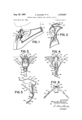
- FIGURE 1 is a fragmentary side view showing, in partly broken away form, the finished pretied necktie as it is worn;
- FIGURE 2 is a rear perspective view of the finished knot portion with the clamp arm in the raised and open position
- FIGURE 3 is a front elevational view of the knot forming body' member embodying the present invention and about which the necktie is knotted and supported;
- FIGURE 4 is a rear elevational view thereof
- FIGURE 5 is a side elevational view thereof with the clamp arm in the open position
- FIGURE 6 is a top plan view thereof
- FIGURE 7 is an exploded perspective view of the knot forming body member
- FIGURE 8 is a fragmentary plan view of a necktie advantageously employed with the improved device.
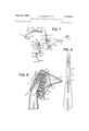
- FIGURE 9 is an enlarged side sectional view of the finished pretied necktie as it is worn.
- the reference numeral 10 generally designates the pretied or preknotted tie which is illustrated as attached to the band 11 of a shirt collar 12 on a wearer W.
- the knot K of the tie 10 is supported and releasably attached to the neckband 11 by a tie or knot forming and support device 13 constructed according to the instant invention.
- the device comprises a winged knot forming and body member 14, a spring plate 16, and a clamp arm 17, an exploded view of these elements being shown in FIGURE 7.
- the knot forming and support device is made up of body member 14 which is advantageously of a molded, somewhat resilient plastic material like polyethylene or indeed of any conventional material whether metal or pressed fiber board. It is of approximately triangular configuration with a bottom, medially located, downwardly rear-wardly inclined apex section 18 and a pair of laterally extending rearwardly directed wings 19 symmetrical to the vertical medial axis of the body member 14. The side edges 20 of member 14 converge downwardly to the apex 18.
- a front wall 21 bridges the wings 19.
- wedge sections 22 which project forwardly from wall 21 at their top ends and which taper downwardly and inwardly toward apex 18.
- wedge sections 22 define and form between themselves a forward chamber or rabbet 23 which serves to receive and seat the inner leg of spring plate 16 as will be hereinafter explained.
- An anchoring aperture 24 is formed in the apex section 18.
- Spring plate 16 is formed of resilient sheet metal. and is disposed wholly forwardly of wings 19. The bottom of plate 16 is tapered to a downwardly rearwardly inclined apex section 25 which overlies the front face of apex 18 and is provided with a registering aperture 26. Plate 16 is secured to body member 14 by a hollow rivet 27 which registers with the apertures 24 and 26.
- the upper part of the plate 16 is provided with a pair of laterally spaced vertical slits which divide the plate upper section into a pair of laterally spaced vertical, resilient outer legs 30, and a central or inner resilient leg 31 intermediate the legs 30, the central leg 31 being seated in forward chamber 23 and flatly abutting the front wall 21.
- Leg 31 is formed at its upper, free end, with a forwardly facing concave knuckle 32.
- legs 30 are formed at their upper, free ends with rearwardly facing concave knuckles 33.
- the clamp arm' 17 comprising angularly related upper and lower legs 35 and 36 respectively, joined by an integrally formed crotch section 37 whereby the clamp arm 17 is rearwardly bowed in the closed position of the device. It is preferred that the included angle between the legs 35 and 36 should be about and that the crotch 37 be spaced from the bridging front wall 31 in the closed position of the clamp arm about .375 inch, thus producing a well bowed construction of the clamp arm.
- the arrangement for swingably supporting the clamp arm 17 and alternatively urging it to its open and closed positions includes a rectangular cross-bar 40 which is engaged between the opposite facing knuckles 32 and 33.
- the cross-bar 40 is formed at the end of a short, arcuate leg 41 which projects from the upper end of leg 35.
- the clamp arm lower leg 36 terminates in a finger piece defining rounded bottom leg 42 which is at the level of the apex 1-8 when the clamp arm is in its closed position.
- the action of the knuckles 32 and 33 on the edges of the cross-bar 40 urges the clamp arm 17 alternatively to its open or closed position.
- the side edges 20 of body member 14 are concave or bowed as illustrated in FIGURE 7.
- An advantage thereof is that the sides of the finished knot K are softer to the touch, thereby being more comfortable to the wearer and also having a more pleasingly draped appearance.
- a most important aspect of this invention is the securing arm 45 which is secured to and outwardly of apex 25 by means of rivet 27 which penetrates through top opening 46 of arm 45.
- FIGURES 3-5 show the extended position of arm 45 before it is used to secure the knotted tie in place.
- Arm 45 is of a bendable metal whether of brass or thin sheet steel of about .025" thickness. Its lower, free end is formed with a concavo-convex head or crown 47 having inwardly directed sharp teeth.48.
- a tie T generally shorter than a conventional tie, i.e. about 35 inches, is laced about the body member 14 to form the knot K in the well understood manner.
- the tie T is advantageously, although not necessarily, provided with apertures 50 and 51 spaced about 4 inches apart, along what corresponds to the upper rear edge of the knot forming section 52 thereof to facilitate the knotting of the tie T on the body member 14 without impeding the locking assembly in any way.
- the clamp arm 17 is first inserted through aperture 51 to better stabilize the parts during the tying operation, the narrower end of the tie then extending downwardly along the front of the body member 14.
- the wider end is draped across a wing top edge, then brought around the front of the Wings 19 so as to substantially encase one wing in a loop, another loop then being formed to encase the other wing while the clamp arm is inserted through the aperture 50.
- the ends are then pulled to tighten the knot. As above stated, this procedure is well known.
- the arm 45 is manually bent upwardly and pressed into the U-shaped position as shown in FIGURES 2 and 9 so as to intersecure the overlapping rear edges of the knot.
- the knot K includes a pair of angularly related overlapping section 54 and 56 which form the rear face of the body member 14.
- the inner edges of the overlapping sections 54 and 56 intersect at a point directly above the position of head 47 when it is pressed inwardly to its fastening position.
- the pretied necktie is attached to the collar by opening the clamp arm 17, inserting it behind the neckband, and snapping it to its locked position to embrace the neckband between the arm head 47 and the leg section or finger piece 42.
- apex 18 of member 14 is considerably thicker than wings 19 or front wall 21.
- the thickness of wings 19 or front wall 21 may be of an inch, while the thickness of apex 18 is W of an inch.
- Apex 18 is tilted rearwardly as illustrated in FIGURE 5.
- the apex 18 serves as a rear spacer which helps tilt the knot K forwardly as illustrated in FIGURE 9.
- bendable arm 45 is most important to this invention. Thus, when the elongated arm 45 is in its downward, extended position, it offers no impediment or hindrance when the tie is being knotted about member 14. Then, when the knot is completed, the operator simply bends arm 45 to its U-shaped fastening position, and of course requiring no stitching. The out of the Way disposition of bendable arm 45 during the tying of the knot is of great benefit and conserves labor time.
- a knot forming and support device adapted to have a necktie knotted thereabout, said device comprising an elongated body member around which the necktie is knotted, a spring clamp member connected to said body member, and an elongated securing arm connected to said body member, said spring clamp member being pivotally connected at its upper end to said body member and its lower end being free, said securing arm extending downwardly from said body member and being bendable intermediate its length whereby it may be bent into U-shape to secure the necktie knot to said body member.
- a knot forming and support device according to claim 1 and wherein said securing arm is formed of manually bendable metal and normally extends downwardly from said body member in substantially elongated position whereby the necktie may be knotted around said body member with minimum hindrance from said securing arm, and the lower end of said securing arm being bendable upwardly to form said securing arm into U-shape so as to secure the knot to said body member.
- a knot forming and support device including a toothed head on the lower, free end of said securing arm adapted to penetrate the knot and firmly secure it to said body member, and said head being of concavo-convex formation.
- a knot forming and support device comprises a pair of laterally extending, rearwardly directed Wing members, a bridge section connecting said wing members, and an apex section under and integral with said bridge section, said apex section being of a thickness greater than that of said wing members and being adapted to receive a shirt neckband between it and the lower free end of said spring clamp member, whereby the thickness of said apex section tends to tilt the necktie upwardly on the wearer.
- a knot forming and support device according to claim 4 and wherein said apex section is tilted rearwardly so as to augment the tilting effect on the wearer.
- a knot forming and support device including a necktie knotted about said body member, said necktie including rearward overlapping sections, said securing arm depending downwardly from said body member and being of itself in U-shape and having a free end pressing against and securing said overlapping sections in position on said body member.
Landscapes
- Engineering & Computer Science (AREA)
- Textile Engineering (AREA)
- Holders For Apparel And Elements Relating To Apparel (AREA)
Description
H. KANTER ET AL NECKTIE KNOT FORMING AND SUPPORT DEVICE Filed April 25, 1966 Aug. 22, 1967 v 2 Sheets-Sheet 1 M INVENTORS BY flQfii 1 /41 v/CZ ATTORNEY Aug. 22, 1967 KANTER ET AL 3,336,601
NECKTIE KNOT FORMING AND SUPPORT DEVICE Filed April 25, 1966 2 Sheets-Sheet United States Patent 3,336,601 NECKTIE KNOT FORMING AND SUPPORT DEVICE Harry Kanter 535 E. 86th St., New York, N.Y. 10028,
and Robert Kallman, 612 Forest Hills Drive, Wilmington, N.C. 28401 Filed Apr. 25, 1966, Ser. No. 551,825 6 Claims. (Cl. 2-153) This invention relates to neckwear and more particularly to neckties of the pretied type provided with clip or clamp means on a knot-forming member for releasably attaching the necktie to a collar neckband.
The general arrangement of such pretied neckties is described in US. Patent Nos. 2,798,226, 3,220,015, and 3,237,208.
In this application we disclose a forming member of novel construction, provided with a spring plate and clamp arm essentially as shown in our Patent No. 3,237,208. However, we have markedly improved the knot securing means in that we provide a bendable arm having a sharply toothed free end or head which can be simply bent over after the knot is formed and which maintains the knot as tied and firmly against the forming member.
The invention will be further understood from the following description and drawings wherein:
FIGURE 1 is a fragmentary side view showing, in partly broken away form, the finished pretied necktie as it is worn;
FIGURE 2 is a rear perspective view of the finished knot portion with the clamp arm in the raised and open position;
FIGURE 3 is a front elevational view of the knot forming body' member embodying the present invention and about which the necktie is knotted and supported;
FIGURE 4 is a rear elevational view thereof;
FIGURE 5 is a side elevational view thereof with the clamp arm in the open position;
FIGURE 6 is a top plan view thereof;
FIGURE 7 is an exploded perspective view of the knot forming body member;
FIGURE 8 is a fragmentary plan view of a necktie advantageously employed with the improved device.
FIGURE 9 is an enlarged side sectional view of the finished pretied necktie as it is worn.
- In the drawings, which illustrate a preferred form of the invention, the reference numeral 10 generally designates the pretied or preknotted tie which is illustrated as attached to the band 11 of a shirt collar 12 on a wearer W. The knot K of the tie 10 is supported and releasably attached to the neckband 11 by a tie or knot forming and support device 13 constructed according to the instant invention. The device comprises a winged knot forming and body member 14, a spring plate 16, and a clamp arm 17, an exploded view of these elements being shown in FIGURE 7.
In the exploded view of FIGURE 7, the knot forming and support device is made up of body member 14 which is advantageously of a molded, somewhat resilient plastic material like polyethylene or indeed of any conventional material whether metal or pressed fiber board. It is of approximately triangular configuration with a bottom, medially located, downwardly rear-wardly inclined apex section 18 and a pair of laterally extending rearwardly directed wings 19 symmetrical to the vertical medial axis of the body member 14. The side edges 20 of member 14 converge downwardly to the apex 18.
A front wall 21 bridges the wings 19. On both defining sides of wall 21 are wedge sections 22 which project forwardly from wall 21 at their top ends and which taper downwardly and inwardly toward apex 18. As a result,
wedge sections 22 define and form between themselves a forward chamber or rabbet 23 which serves to receive and seat the inner leg of spring plate 16 as will be hereinafter explained. An anchoring aperture 24 is formed in the apex section 18.
Spring plate 16 is formed of resilient sheet metal. and is disposed wholly forwardly of wings 19. The bottom of plate 16 is tapered to a downwardly rearwardly inclined apex section 25 which overlies the front face of apex 18 and is provided with a registering aperture 26. Plate 16 is secured to body member 14 by a hollow rivet 27 which registers with the apertures 24 and 26.
The upper part of the plate 16 is provided with a pair of laterally spaced vertical slits which divide the plate upper section into a pair of laterally spaced vertical, resilient outer legs 30, and a central or inner resilient leg 31 intermediate the legs 30, the central leg 31 being seated in forward chamber 23 and flatly abutting the front wall 21. Leg 31 is formed at its upper, free end, with a forwardly facing concave knuckle 32. On the other hand, legs 30 are formed at their upper, free ends with rearwardly facing concave knuckles 33.
Swingably supported by the knuckles 32 and 33, and cooperating with the body member 14 to create a fastening device is the clamp arm' 17 comprising angularly related upper and lower legs 35 and 36 respectively, joined by an integrally formed crotch section 37 whereby the clamp arm 17 is rearwardly bowed in the closed position of the device. It is preferred that the included angle between the legs 35 and 36 should be about and that the crotch 37 be spaced from the bridging front wall 31 in the closed position of the clamp arm about .375 inch, thus producing a well bowed construction of the clamp arm.
The arrangement for swingably supporting the clamp arm 17 and alternatively urging it to its open and closed positions includes a rectangular cross-bar 40 which is engaged between the opposite facing knuckles 32 and 33. The cross-bar 40 is formed at the end of a short, arcuate leg 41 which projects from the upper end of leg 35. The clamp arm lower leg 36 terminates in a finger piece defining rounded bottom leg 42 which is at the level of the apex 1-8 when the clamp arm is in its closed position. The action of the knuckles 32 and 33 on the edges of the cross-bar 40 urges the clamp arm 17 alternatively to its open or closed position.
The side edges 20 of body member 14 are concave or bowed as illustrated in FIGURE 7. An advantage thereof is that the sides of the finished knot K are softer to the touch, thereby being more comfortable to the wearer and also having a more pleasingly draped appearance.
A most important aspect of this invention is the securing arm 45 which is secured to and outwardly of apex 25 by means of rivet 27 which penetrates through top opening 46 of arm 45.
FIGURES 3-5 show the extended position of arm 45 before it is used to secure the knotted tie in place. Arm 45 is of a bendable metal whether of brass or thin sheet steel of about .025" thickness. Its lower, free end is formed with a concavo-convex head or crown 47 having inwardly directed sharp teeth.48.
The invention is practiced as follows: First, a tie T, generally shorter than a conventional tie, i.e. about 35 inches, is laced about the body member 14 to form the knot K in the well understood manner. As is well known, the tie T is advantageously, although not necessarily, provided with apertures 50 and 51 spaced about 4 inches apart, along what corresponds to the upper rear edge of the knot forming section 52 thereof to facilitate the knotting of the tie T on the body member 14 without impeding the locking assembly in any way. Briefly, and in order to set forth herein the latest developments in the tying procedure, the clamp arm 17 is first inserted through aperture 51 to better stabilize the parts during the tying operation, the narrower end of the tie then extending downwardly along the front of the body member 14. The wider end is draped across a wing top edge, then brought around the front of the Wings 19 so as to substantially encase one wing in a loop, another loop then being formed to encase the other wing while the clamp arm is inserted through the aperture 50. The ends are then pulled to tighten the knot. As above stated, this procedure is well known.
Thereafter the arm 45 is manually bent upwardly and pressed into the U-shaped position as shown in FIGURES 2 and 9 so as to intersecure the overlapping rear edges of the knot.
It will be observed that the knot K includes a pair of angularly related overlapping section 54 and 56 which form the rear face of the body member 14. The inner edges of the overlapping sections 54 and 56 intersect at a point directly above the position of head 47 when it is pressed inwardly to its fastening position.
The pretied necktie is attached to the collar by opening the clamp arm 17, inserting it behind the neckband, and snapping it to its locked position to embrace the neckband between the arm head 47 and the leg section or finger piece 42.
This invention includes the particular formation of apex 18 of member 14. Thus, apex 18 is considerably thicker than wings 19 or front wall 21. For example, the thickness of wings 19 or front wall 21 may be of an inch, while the thickness of apex 18 is W of an inch. Apex 18 is tilted rearwardly as illustrated in FIGURE 5. Thus the apex 18 serves as a rear spacer which helps tilt the knot K forwardly as illustrated in FIGURE 9.
The provision of bendable arm 45 is most important to this invention. Thus, when the elongated arm 45 is in its downward, extended position, it offers no impediment or hindrance when the tie is being knotted about member 14. Then, when the knot is completed, the operator simply bends arm 45 to its U-shaped fastening position, and of course requiring no stitching. The out of the Way disposition of bendable arm 45 during the tying of the knot is of great benefit and conserves labor time.
We have shown a preferred embodiment of this invention, but it is understood that numerous changes and omissions may be made without departing from its spirit.
What is claimed is:
1. A knot forming and support device adapted to have a necktie knotted thereabout, said device comprising an elongated body member around which the necktie is knotted, a spring clamp member connected to said body member, and an elongated securing arm connected to said body member, said spring clamp member being pivotally connected at its upper end to said body member and its lower end being free, said securing arm extending downwardly from said body member and being bendable intermediate its length whereby it may be bent into U-shape to secure the necktie knot to said body member.
2. A knot forming and support device according to claim 1 and wherein said securing arm is formed of manually bendable metal and normally extends downwardly from said body member in substantially elongated position whereby the necktie may be knotted around said body member with minimum hindrance from said securing arm, and the lower end of said securing arm being bendable upwardly to form said securing arm into U-shape so as to secure the knot to said body member.
3. A knot forming and support device according to claim 2 and including a toothed head on the lower, free end of said securing arm adapted to penetrate the knot and firmly secure it to said body member, and said head being of concavo-convex formation.
4. A knot forming and support device according to claim 1 and wherein said body member comprises a pair of laterally extending, rearwardly directed Wing members, a bridge section connecting said wing members, and an apex section under and integral with said bridge section, said apex section being of a thickness greater than that of said wing members and being adapted to receive a shirt neckband between it and the lower free end of said spring clamp member, whereby the thickness of said apex section tends to tilt the necktie upwardly on the wearer.
5. A knot forming and support device according to claim 4 and wherein said apex section is tilted rearwardly so as to augment the tilting effect on the wearer.
6. A knot forming and support device according to claim 1 and including a necktie knotted about said body member, said necktie including rearward overlapping sections, said securing arm depending downwardly from said body member and being of itself in U-shape and having a free end pressing against and securing said overlapping sections in position on said body member.
References Cited UNITED STATES PATENTS 1,603,885 10/1926 Van Dyk 2153 1,636,368 7/1927 Johnson 2-153 2,798,226 7/ 1957 Kanter 2153 3,220,015 11/1965 Kanter et al. 2-153 3,222,684 12/1965 Kanter et al 2-153 3,237,208 3/1966 Kanter et al. 2-153 PATRICK D. LAWSON, Primary Examiner.
Claims (1)
1. A KNOT FORMING AND SUPPORT DEVICE ADAPTED TO HAVE A NECKTIE KNOTTED THEREABOUT, SAID DEVICE COMPRISING AN ELONGATED BODY MEMBER AROUND WHICH THE NECKTIE IS KNOTTED, A SPRING CLAMP MEMBER CONNECTED TO SAID BODY MEMBER, AND AN ELONGATED SECURING ARM CONNECTED TO SAID BODY MEMBER, SAID SPRING CLAMP MEMBER BEING PIVOTALLY CONNECTED AT ITS UPPER END TO SAID BODY MEMBER AND ITS LOWER END BEING FREE, SAID SECURING ARM EXTENDING DOWNWARDLY FROM SAID BODY MEMBER AND BEING BENDABLE INTERMEDIATE ITS LENGTH WHEREBY IT MAY BE BENT INTO U-SHAPE TO SECURE THE NECKTIE KNOT TO SAID BODY MEMBER.
Priority Applications (1)
| Application Number | Priority Date | Filing Date | Title |
|---|---|---|---|
| US551825A US3336601A (en) | 1966-04-25 | 1966-04-25 | Necktie knot forming and support device |
Applications Claiming Priority (1)
| Application Number | Priority Date | Filing Date | Title |
|---|---|---|---|
| US551825A US3336601A (en) | 1966-04-25 | 1966-04-25 | Necktie knot forming and support device |
Publications (1)
| Publication Number | Publication Date |
|---|---|
| US3336601A true US3336601A (en) | 1967-08-22 |
Family
ID=24202838
Family Applications (1)
| Application Number | Title | Priority Date | Filing Date |
|---|---|---|---|
| US551825A Expired - Lifetime US3336601A (en) | 1966-04-25 | 1966-04-25 | Necktie knot forming and support device |
Country Status (1)
| Country | Link |
|---|---|
| US (1) | US3336601A (en) |
Cited By (5)
| Publication number | Priority date | Publication date | Assignee | Title |
|---|---|---|---|---|
| US3513483A (en) * | 1969-01-09 | 1970-05-26 | Hope City | Necktie knot forming and support system |
| USD267289S (en) | 1980-10-24 | 1982-12-21 | John Najarian | Necktie knot support |
| US4875239A (en) * | 1988-08-09 | 1989-10-24 | Patterson Jr John A | Pre-tied necktie |
| US6021522A (en) * | 1998-07-28 | 2000-02-08 | Najarian; John | Necktie knot support assembly |
| US6467094B1 (en) * | 2002-02-26 | 2002-10-22 | Eastern Creative Industries, Inc. | Necktie knot support assembly |
Citations (6)
| Publication number | Priority date | Publication date | Assignee | Title |
|---|---|---|---|---|
| US1603885A (en) * | 1926-07-22 | 1926-10-19 | Peter Van Dyk | Necktie holder |
| US1636368A (en) * | 1927-03-28 | 1927-07-19 | Aron E Johnson | Necktie holder |
| US2798226A (en) * | 1956-11-08 | 1957-07-09 | France Neckwear Co Inc | Necktie form |
| US3220015A (en) * | 1964-12-07 | 1965-11-30 | Kanter Harry | Necktie knot forming device |
| US3222684A (en) * | 1964-12-07 | 1965-12-14 | Kanter Harry | Necktie knot device |
| US3237208A (en) * | 1965-06-15 | 1966-03-01 | Kanter Harry | Necktie knot forming device |
-
1966
- 1966-04-25 US US551825A patent/US3336601A/en not_active Expired - Lifetime
Patent Citations (6)
| Publication number | Priority date | Publication date | Assignee | Title |
|---|---|---|---|---|
| US1603885A (en) * | 1926-07-22 | 1926-10-19 | Peter Van Dyk | Necktie holder |
| US1636368A (en) * | 1927-03-28 | 1927-07-19 | Aron E Johnson | Necktie holder |
| US2798226A (en) * | 1956-11-08 | 1957-07-09 | France Neckwear Co Inc | Necktie form |
| US3220015A (en) * | 1964-12-07 | 1965-11-30 | Kanter Harry | Necktie knot forming device |
| US3222684A (en) * | 1964-12-07 | 1965-12-14 | Kanter Harry | Necktie knot device |
| US3237208A (en) * | 1965-06-15 | 1966-03-01 | Kanter Harry | Necktie knot forming device |
Cited By (5)
| Publication number | Priority date | Publication date | Assignee | Title |
|---|---|---|---|---|
| US3513483A (en) * | 1969-01-09 | 1970-05-26 | Hope City | Necktie knot forming and support system |
| USD267289S (en) | 1980-10-24 | 1982-12-21 | John Najarian | Necktie knot support |
| US4875239A (en) * | 1988-08-09 | 1989-10-24 | Patterson Jr John A | Pre-tied necktie |
| US6021522A (en) * | 1998-07-28 | 2000-02-08 | Najarian; John | Necktie knot support assembly |
| US6467094B1 (en) * | 2002-02-26 | 2002-10-22 | Eastern Creative Industries, Inc. | Necktie knot support assembly |
Similar Documents
| Publication | Publication Date | Title |
|---|---|---|
| US3405408A (en) | Tie holder | |
| US2631292A (en) | Necktie device | |
| US4337539A (en) | Necktie knot support assembly | |
| US3336600A (en) | Necktie knot former and support | |
| US3336601A (en) | Necktie knot forming and support device | |
| US3222684A (en) | Necktie knot device | |
| US1367461A (en) | Necktie-former | |
| US3220015A (en) | Necktie knot forming device | |
| US3365726A (en) | Necktie knot device | |
| US3218650A (en) | Ornamental neckwear | |
| US3221343A (en) | Necktie clip | |
| US3513483A (en) | Necktie knot forming and support system | |
| US3343176A (en) | Fastening means for necktie knot former and support | |
| US2444548A (en) | Necktie accessory | |
| US3237208A (en) | Necktie knot forming device | |
| US3263237A (en) | Pre-knotted necktie | |
| US3820166A (en) | Device for supporting and forming a necktie knot | |
| US3426361A (en) | Ready-made necktie form | |
| US3538511A (en) | Necktie | |
| US2287887A (en) | Scarf and sash | |
| US3262166A (en) | Necktie holder | |
| US1791638A (en) | Tie | |
| US2528356A (en) | Necktie clip knotter | |
| US2063512A (en) | Necktie | |
| US2052161A (en) | Necktie construction |