US3335875A - Hydraulic gantry crane - Google Patents
Hydraulic gantry crane Download PDFInfo
- Publication number
- US3335875A US3335875A US519623A US51962366A US3335875A US 3335875 A US3335875 A US 3335875A US 519623 A US519623 A US 519623A US 51962366 A US51962366 A US 51962366A US 3335875 A US3335875 A US 3335875A
- Authority
- US
- United States
- Prior art keywords
- crane
- supports
- wheeled
- load
- support
- Prior art date
- Legal status (The legal status is an assumption and is not a legal conclusion. Google has not performed a legal analysis and makes no representation as to the accuracy of the status listed.)
- Expired - Lifetime
Links
- 230000005484 gravity Effects 0.000 claims description 3
- VJYFKVYYMZPMAB-UHFFFAOYSA-N ethoprophos Chemical compound CCCSP(=O)(OCC)SCCC VJYFKVYYMZPMAB-UHFFFAOYSA-N 0.000 claims 2
- 238000005096 rolling process Methods 0.000 description 6
- 239000012530 fluid Substances 0.000 description 1
- 230000004048 modification Effects 0.000 description 1
- 238000012986 modification Methods 0.000 description 1
- 238000009877 rendering Methods 0.000 description 1
Images
Classifications
-
- B—PERFORMING OPERATIONS; TRANSPORTING
- B66—HOISTING; LIFTING; HAULING
- B66C—CRANES; LOAD-ENGAGING ELEMENTS OR DEVICES FOR CRANES, CAPSTANS, WINCHES, OR TACKLES
- B66C19/00—Cranes comprising trolleys or crabs running on fixed or movable bridges or gantries
- B66C19/02—Cranes comprising trolleys or crabs running on fixed or movable bridges or gantries collapsible
Description
Aug- 1 5, 1957 P. FACHINETTI 3,335,875
HYDRAULIC GANTRY CRANE Filed Jan. lO, 1966 '7 Sheets-Sheet l whim ATTORNEYS 7 Sheets-Sheet 2 Filed Jan. lO, 1965 md Mm ATTORNEYS Allg 15, 1967 P. FACHINETTI HYDRAULIC GANTRY CRANE 7 Sheets-Sheet 5 Filed Jan. l0, 1966 INVENTOR Aug. 15, i196? P. FACHINETTI Y HYDRAULIC GANTRY CRANE '7 Sheets-Sheet 4 Filed Jan. l0, 1966 Allg- 5, w57 P. FACHINETTI 3,335,875
7 Sheets-Sheet 5 Filed Jan. lO, 1966 /NVENT/ le/e Gioi/HMV) {GCH/'Me Tri Aug' 15, 1967 P. FACHINETTI 3,335,875
HYDRAULIC GANTRY CRANE Filed Jan. l0, 1966 7 Sheets-Sheet 6 Eyd. 165 TL I fj" 29 f3] Q ZQ.
U7 Fay 57 37 L L?) l J6J\ Fly f 57 5c. 37 Y j 7 TOR/VEYS Aug. l5, i967 P. FACHINETTI HYDRAULIC GANTRY CRANE Filed Jan. lo,l 196e 7 Sheets-Sheet '7 TTOR/VE YS United States Patent O M 3,335,875 HYDRAULIC GANTRY CRANE Piergiovanni Fachinetti, Varese, Italy, assignor to Anderston Clyde Engineers Limited, Bolton, England Filed `lan. 10, 1966, Ser. No. 519,623 Claims priority, applizcation Italy, Jan. 9, 1965, 6/65 13 Claims. (Cl. 212-13) ABSTRACT OF THE DISCLGSURE This invention relates to mobile cranes.
In a known mobile crane, a gantry is provided on which the crane lifting structure runs, and in this case the direction of motion of the crane structure is restricted to the direction of supporting and guiding rails on the gantry.
In another mobile crane, a wheeled A frame is provided with lifting apparatus on the cross bar of the frame whereby loads may be lifted by the apparatus, for example, a block and tackle, and the A-frame may straddle a lorry so that the load may be loaded onto the lorry. Here again, the direction of movement of the A frame is somewhat restricted and can only be altered by considerable eifort and provided there is suiiicient lloor space available.
Another mobile crane is a fork lift truck and in this case a mobile truck has a fork lifting mechanism which overhangs the truck body with the result that, in order to support the loads, the truck must be of considerable mass to prevent overbalancing.
An object of this invention is to provide a crane which is more maneuverable than the cranes previously known. It will be readily appreciated that the value to a user of a crane depends not only on the power and convenience of operation of the lifting mechanism, but upon the maneuverability of the crane. This affects the operation of the crane in two ways, namely in its ability to get at an awkward load in an awkward place in order to deploy the lifting mechanism upon it, and secondly in its ability to perform the reverse operation, and lay the load down again in a possibly awkward place, after having carried it on a possibly awkward journey in a confined or obstructed space.
It has now been found that a crane can be made particularly maneuverable by mounting it upon a three point support of wheeled supports.
By wheeled support it is to be understood that while a single wheel may be employed for each support, it is sometimes convenient to Vuse two or more wheels in close juxtaposition, as at the rear of heavy lorries, in order to provide a more substantial support. By wheeled support therefore is meant throughout this specification a single wheel or a plurality of wheels in close juxtaposition.
The three point wheeled support depends for its efectiveness on two of the said wheeled supports being rotatable for steering about substantially vertical axes through equal angles but in opposite directions. It is of course most convenient if there are steering means which rotate the 3,335,875 Patented Aug. l5, 1967 steered wheeled supports simultaneously, though they could be rotated separately.
lt is also most convenient if the whole arrangement is symmetrical, so that the three wheeled supports form a substantially isosceles triangle, with the two steered wheeled supports forming the base of the triangle. Further, symmetry leading to greater convenience of operation may be secured by making sure that the steered wheel supports are symmetrical to the base of the triangle in all positions, then of course if they are rotated to an extent premitting the wheels of the supports to lie in planes parallel to each other, those planes will be at right angles to the base of the triangle. If the Iwheels of the supports can be rotate-d to an extent permitting them to lie in the same plane it is obvious that that plane can only be a plane containing the base of the triangle, and if the wheels of the wheeled supports can be rotated so as to lie in the same plane and are thereafter moved simultaneously through equal angles but in opposite directions, they must always be symmetrical with respect to the base of the triangle.
Whether symmetry is -observed or not, by means of the arrangement of moving the steered wheeled supports in opposite directions to toe in (or toe out as the case may be) the Whole crane can be rotated about a vertical axis which can be chosen to lie at any point either inside or outside the triangle (though if symmetry is observed the locus of such points will lie on a line normal to the base of the triangle) and which will be determined by the point where the rolling axes of the steered wheeled supports meet. When the rolling axes of the steered wheeled supports are parallel or coincide the crane rotates about a vertical axis at infinity, or in other words moves in a straight line.
It is this ability of the steered wheel supports to toe in or out that gives the crane according to the present invention its great maneuvera-bility, and a three point support contributes to the results because if there is a three point support it is only necessary to steer the two steered wheeled supports and it is not necessary to steer the third lwheeled support.
If the two steered wheeled supports are symmetrically disposed with regard to the third wheeled support in every steering position, it is only necessary to arrange the third wheeled support to have the rolling axis of its wheel or wheels at right angles to the base of the triangle and then its rolling axis will always pass through the point of intersection of the rolling axes of the two steered wheel supports. Otherwise it is necessary to caster the third wheeled support in order for this to take place, and in any event castering the third wheeled support provides increased maneuverability,
lt further increases the general lutility of a crane so supported for maneuverability if the crane is of the inverted U beam type where the beam is raised by hydraulic jacks, as such a type of crane provides the maximum amount of room beneath the lifting tackle to take the fullest advantage of the novel support provided by this invention. Usually the lifting beam of such a crane is a crossbar with two supporting jacks, but sometimes such a cross- Ibar is bifurcated and may have three or even more jacks supporting it.
Obviously the load lifting points of the crane must fall vertically inside the triangle formed by the wheeled supports if problems of overbalancing are to be avoided.
Thus, according to the present invention there is provided a mobile crane including a crane structure, three wheeled supports which support the crane structure and render it mobile and maneuverable for lifting and carrying the load, the wheeled supports being positioned at the apices of a triangle, two of the sai-d supports being each rotatable about a substantially vertical axis, and steering means connected to the rotatable wheeled supports and adapted so as to rotate each Iof the said supports through equal angles but in opposite directions, the crane structure being adapted to carry the load with the centre of gravity of such load located vertically inside the said triangle.
An embodiment of the invention will now be described, by way of example, with reference to the accompanying drawings, wherein:
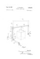
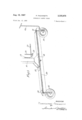
FIG. 1 is a perspective view o a mobile crane according to the invention;
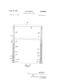
FIG. 2 is a side view of the crane `of FIG. l;
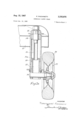
FIG. 2a is a sectional View showing a detail;
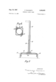
FIG. 3 is a corresponding end view;
FIG. 4 is a sectional plane taken on the line IV-IV of FIG. 2. I
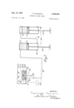
FIG. 5 is an enlarged view of one end.
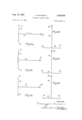
FIGS. 6a, b, c, d, e and f are diagrammatic plans indicating several of the positions which can be taken up by the crane of FIG. l; and
FIG. 7 is a schematic view indicating a hydraulic system which may be used as the lifting means for the crane.
Referring to the drawings, there is shown in FIG. 1 a mobile crane which is supported on three wheeled supports 10, 11 and 12 rendering the crane mobile, and of which the supports 10, 11 are interconnected by steering means housed in a horizontal channel-sectioned frame 13. The third wheeled support 12 supports the lower end of one limb of an inverted U-shaped structure 14 and the other limb is secured by a bracket 15 to the centre of the channel frame 13.
The point 1 or points 1 of load attachment is or are located on a line or lines which are normal to and pass through the triangular plane detined by the three wheeled supports which form the apices thereof.
Each limb of the structure 14 is in two telescoping parts, a box sectioned outer tube 16 and a cylindrical inner tube 17, the cylindrical tube projecting out of the top end of the tube 16 and the two tubes 16 are interconnected by a cylindrical section crossbar 13. Contained within each limb of the U frame 13 is a hydraulic rain or jack 19 of which the cylinder 20 is contained Within the inner tube 17. The top of the cylinder 20 is connected to the top of the tube 17 and the piston 21 has its rod 22A depending downwards and is connected to the lower end of the outer tube 16. The jacks are interconnected hydraulically as shown in FIG. 7 and the arrangement is such that upon pressurising of the jacks 19, the cylinders 20 move upwards, by reaction, and raise the crossbar 18 to which the load is attached, thereby raising the load. The jacks 19 move by the same amount by virtue of the hydraulic interconnection, but this Will be discussed in more detail hereinafter.
Supply of hydraulic uid to operate the jacks 19 is by a manual pump 22 operated by rocking a handle 23 connected to the pump 22 by a connecting rod 24. A control release valve is incorporated in the pump 22 and this is opened, to allow the load to descend by a hand wheel 25 and control bar 26. As an alternative to the hand pump 22, there may be provided an electric motor and driven PUmP- For the guided sliding of the inner tube 17 in the outer tube 16, the inner tube 17 has diagonally opposite angle pieces 27 welded thereto which slide on bearing pad 28, which are lubricated, mounted on the interior of the tube 16.
The wheeled support 12 is castered on the lower end of the tube 16 and is provided with a pair of freely rotatable wheels 29 on opposite sides of the axis of castering. Attached to the support 12 is a handle 30 which may be maneuvered to alter the angularity of the wheels 29. When the handle is not in use, it can be pivoted to a vertical position and clipped therein in a clip (not shown) on the tube 16.
Referring now to FIG. 2a, there is shown in section one of the steered wheeled supports 10, the other 11 being identical. The support 10 comprises a kingpin 31 journalled in a tubular casing 31A for rotation about a vertical axis 32 and in bearings 33, 34. The kingpin 31 has, at its upper end and within the box frame 13, a sprocket 35 and at its lower end a stub axle 36 to which is journalled a wheel 37. The Wheel 37 has a rubber tire 38 as have the wheels 29.
In FIGURE 5 the two sprockets 35 are shown and it will be observed that these are interconnected by an endless chan 39 which forms part of the steering means, having a twist therein whereby feeding movement of the chain 39 causes the kingpins 31, and hence the supports 10, 11 to turn in opposite directions by the same angle. It is however, necessary that in one position of the steering means, the wheels 37 lie in planes which are parallel to one another; that is the wheels are parallel, to ensure symmetrical disposition of the wheels 37 about the normal bisector of the line joining their centres. The turning of the supports is achieved by means of a handle 11A pivotally attached to one of the kingpins 31 in a manner similar to that of the handle 30. By means of this steering arrangement, the wheels of the steered supported 10, 11 may take up, for example, any one of the positions shown in FIGS. 6a, b, c, d, e and f. In these figures the rolling circle of each wheel is shown with the exception of FIGS. 6a and b as in these cases the wheels 37 and 29 are all parallel the crane being arranged to be pushed in the direction of the crossbar 18 in FIG. 6a and in the normal direction in FIG. 6b.
In FIGS. 6c, d, e and f, the crane is arranged for turning movement, the steered Wheels being appropriately positioned and in each case the wheels 37 and 29 are positioned to give easy maneuverability of the crane as the wheels 37, 29 lie on circles which have a common centre, Other positions fulfilling this requirement may be attained, but the position indicated in FIG. 6c is of interest in that the diameter of the biggest circle is little more than the overall dimension of the crane so that the crane can turn round in almost the space which it occupies.
The hydraulic circuit for the crane is shown in FIG. 7 and it includes a reservoir 40 which houses the manual pump 22. This pump is of the double acting type and includes a piston 41 slidable in a bore 42 of a -valve body 43. The to and fro motion of the piston 41 is by means of the rocking handle 23 and on each stroke of the piston as regards one piston face, oil is sucked into the pump through a non-return valve 44 and as regards the other piston face oil is pumped through another non-return valve 45, into a feed line 46. Thus, there are two nonreturn valves 44 and two non-return valves 45; both nonreturn valves 45 lead to the feed line 46. The feed line 46 leads to the crown side of the piston 21 and the rod side of the piston 21 is connected to the second jack 19 by a conduit 47 which leads to the crown side of the piston 21 of the second jack 19. The rod side of the piston 21 of the second jack 19 is open to atmosphere through a release port 4S. The cylinder below piston 21 of the first jack 19 and the crown side of the piston 21 of the second jack 19 are not completely lled with oil, but partially contain oil and air. To this end, the first jack is provided with an oil inlet 49 to the rod side and an oil release plug to the crown side to the second jack. Thus, in order to raise the jacks 19 oil is supplied under pressure via the feed line 46 to the first jack 19, whereupon the cylinder 20 commences to move upwards and the oil in the rod side of the first piston is forced into the crown side of the second cylinder as the second cylinder 20 moves upwards thereby raising the load which is attached to the crossbar 18.
In order to lower the load, the control release valve 50, which is in communication with the feed line 46, is opened and the oil ows back through the feed line to the reservoir. The feed line 46 is also provided connected to a pressure relief Valve 51 to prevent the pressure in the jacks 19 from becoming excessive.
FIG. 7 also indicates, in dotted lines, the circuit when a driven pump is used. In this case oil is drawn by the pump 52 through a filter 53 and delivers it to the rst jack 19. Operation and release of the pressure is in a manner similar to the operation described in connection with the manual control.
In a larger version of the mobile crane described a suitable power source for driving the crane is provided and there is provided an operators platform on which an operator may sit and steering is effected -by a steering wheel provided on the platform.
The embodiment of the invention as described has the advantages that the load supported by the crane is held very stable and the crane can be very easily maneuvered within a small space, the direction of movement of the crane is not restricted, the wheels can be arranged to give stability during raising of the load and the hydraulic lifting arrangements ensures a steady lifting of the load.
In a modification of the invention, rfour wheeled supports may bet used, these being arranged at the corners of a rectangle or square and operating on the .principles herein described.
What I claim is:
1. A mobile crane including a crane structure, three wheeled supports which support the crane structure and render it mobile and maneuverable for lifting and carrying the load, the wheeled supports being positioned at the apices of a triangle, two of the said supports being each rotatable about a substantially vertical axis, and steering means connected to the rotatable wheeled supports and adapted so as to rotate each of the said supports through equal angles vbut in opposite directions, the crane structure being adapted to carry the load with the centre of gravity of such load located vertically inside the said triangle.
2. A mobile crane according to claim 1 wherein the steering means are connected to the said two Wheeled supports so that in one position the wheels of the steerable Wheeled supports lie in parallel planes.
3. A mobile crane according to claim 1 in which the third wheeled support is castered to the crane structure.
4. A mobile crane according to claim 3, in which the third wheeled support has two wheels symmetrically disposed in relation to the axis of castering.
5. A mobile crane according to claim 3, in which there are means to rotate the said third wheeled support about an axis substantially vertical relative to the crane structure.
6. A mobile crane according to claim 1 in which the steering means includes a sprocket connected to each of the said two wheeled supports and a chain passing round each sprocket, the ends of the said two chains being connected together by connecting means in twisted fashion to provide means for giving said simultaneous rotation in opposite directions of the said supports.
7. A mobile crane according to claim 6 in which the steering means include a handle or wheel attached to one of the said two wheeled supports and adapted to rotate the same about its said substantially vertical axis.
8. A mobile crane according to claim 1 in which the crane structure is of generally inverted U-shape and the lower end of one limb is supported by the said two steered wheeled supports, and the lower end of the other limb is supported by the said third wheeled support, so that the U-shaped crane structure may straddle the load to be lifted before lifting.
9. A mobile crane according to claim 8 in which the crane structure has two vertical limbs and a cross bar connecting the tops of the limbs, and a Ibeam which is connected to the lower end of one limb, and the wheeled supports are disposed one at each end of the horizontal box beam and the third at the lower end of the other limb.
10. A mobile crane according to claim 9 including means for lifting the cross bar, to which a load may be attached.
11. A mobile crane according to claim 10 in which the means are hydraulic pistons and cylinders one being slidably located each lim-b and the jacks 'being operable to raise the cross `bar of the U-structure which is for supporting the load.
12. A mobile crane according to claim 11 including a manually operable double acting pump for supplying pressure uid to the hydraulic pistons and cylinders.
13. A mobile crane according to claim 11 including an electric motor and a pump driven thereby for supplying pressure fluid to the hydraulic pistons and cylinders.
References Cited UNITED STATES PATENTS 2,549,120l 4/1951 Ormsby 254-139.l 2,950,121 8/1960 Fischer 280-47.11 3,211,306 10/1965 Nissen et al. IS7- 8.59
FOREIGN PATENTS 549,124 11/ 1942 Great Britain.
ANDRES H. NIELSEN, Primary Examiner.
Claims (1)
1. A MOBILE CRANE INCLUDING A CRANE STRUCTURE, THREE WHEELED SUPPORTS WHICH SUPPORT THE CRANE STRUCTURE AND RENDER IT MOBILE AND MANEUVERABLE FOR LIFTING AND CARRYING THE LOAD, THE WHEELED SUPPORTS BEING POSITIONED AT THE APICES OF A TRIANGLE, TWO OF THE SAID SUPPORTS BEING EACH ROTATABLE ABOUT A SUBSTANTIALLY VERTICAL AXIS, AND STEERING MEANS CONNECTED TO THE ROTATABLE WHEELED SUPPORTS AND ADAPTED SO AS TO ROTATE EACH OF THE SAID SUPPORTS THROUGH EQUAL ANGLES BUT IN OPPOSITE DIRECTIONS, THE CRANE STRUCTURE BEING ADAPTED TO CARRY THE LOAD WITH THE CENTRE OF GRAVITY OF SUCH LOAD LOCATED VERTICALLY INSIDE THE SAID TRIANGLE.
Applications Claiming Priority (1)
| Application Number | Priority Date | Filing Date | Title |
|---|---|---|---|
| IT52665 | 1965-01-09 |
Publications (1)
| Publication Number | Publication Date |
|---|---|
| US3335875A true US3335875A (en) | 1967-08-15 |
Family
ID=11099093
Family Applications (1)
| Application Number | Title | Priority Date | Filing Date |
|---|---|---|---|
| US519623A Expired - Lifetime US3335875A (en) | 1965-01-09 | 1966-01-10 | Hydraulic gantry crane |
Country Status (3)
| Country | Link |
|---|---|
| US (1) | US3335875A (en) |
| BE (1) | BE682072A (en) |
| GB (1) | GB1121251A (en) |
Cited By (8)
| Publication number | Priority date | Publication date | Assignee | Title |
|---|---|---|---|---|
| US4381839A (en) * | 1981-03-02 | 1983-05-03 | Riggers Manufacturing Co. | Gantry having adjustable side supports |
| EP0092152A2 (en) * | 1982-04-16 | 1983-10-26 | Konrad Wolfgang Maier | Crane and transporting device, especially for transporting gravestones and gravestone slabs |
| US5865327A (en) * | 1989-10-24 | 1999-02-02 | J & R Engineering Co., Inc. | Hydraulic boom for gantry and the like |
| US6685038B1 (en) | 1999-10-15 | 2004-02-03 | J & R Engineering Company, Inc. | Extendible boom with locking mechanism having equalizer arrangement |
| US20140215783A1 (en) * | 2011-07-28 | 2014-08-07 | Vestas Wind Systems A/S | Production facility comprising a transport system for processing elongated products, in particular wind turbine blades, with elongated mould assemblies |
| US10093217B2 (en) | 2016-06-07 | 2018-10-09 | Antu Eduardo CHICAHUALA | Movable frame including gantry |
| CN112027900A (en) * | 2020-08-15 | 2020-12-04 | 陆少益 | Double-station synchronous bridge double-hoisting-point hoisting device |
| US20210147195A1 (en) * | 2019-11-19 | 2021-05-20 | Marco Belanger | Lifting rig for moving heavy objects on rooftops |
Families Citing this family (1)
| Publication number | Priority date | Publication date | Assignee | Title |
|---|---|---|---|---|
| FR2420502A1 (en) * | 1978-03-23 | 1979-10-19 | Alsthom Cgee | Mobile gantry crane - has adjustable span and height to allow use on tracks of varying width |
Citations (4)
| Publication number | Priority date | Publication date | Assignee | Title |
|---|---|---|---|---|
| GB549124A (en) * | 1940-07-15 | 1942-11-06 | William Platts Kellett | Improvements in or relating to mechanism for raising and lowering the deck of transport vehicles |
| US2549120A (en) * | 1947-06-02 | 1951-04-17 | Lucienne M Ormsby | Crane |
| US2950121A (en) * | 1958-09-29 | 1960-08-23 | James L Fisher | Steering mechanism for microphone dolly and the like |
| US3211306A (en) * | 1962-09-08 | 1965-10-12 | Nissen Peter List | Load carrying vehicle |
-
1966
- 1966-01-07 GB GB780/66A patent/GB1121251A/en not_active Expired
- 1966-01-10 US US519623A patent/US3335875A/en not_active Expired - Lifetime
- 1966-06-03 BE BE682072D patent/BE682072A/xx unknown
Patent Citations (4)
| Publication number | Priority date | Publication date | Assignee | Title |
|---|---|---|---|---|
| GB549124A (en) * | 1940-07-15 | 1942-11-06 | William Platts Kellett | Improvements in or relating to mechanism for raising and lowering the deck of transport vehicles |
| US2549120A (en) * | 1947-06-02 | 1951-04-17 | Lucienne M Ormsby | Crane |
| US2950121A (en) * | 1958-09-29 | 1960-08-23 | James L Fisher | Steering mechanism for microphone dolly and the like |
| US3211306A (en) * | 1962-09-08 | 1965-10-12 | Nissen Peter List | Load carrying vehicle |
Cited By (11)
| Publication number | Priority date | Publication date | Assignee | Title |
|---|---|---|---|---|
| US4381839A (en) * | 1981-03-02 | 1983-05-03 | Riggers Manufacturing Co. | Gantry having adjustable side supports |
| EP0092152A2 (en) * | 1982-04-16 | 1983-10-26 | Konrad Wolfgang Maier | Crane and transporting device, especially for transporting gravestones and gravestone slabs |
| EP0092152A3 (en) * | 1982-04-16 | 1984-07-04 | Konrad Wolfgang Maier | Crane and transporting device, especially for transporting gravestones and gravestone slabs |
| US5865327A (en) * | 1989-10-24 | 1999-02-02 | J & R Engineering Co., Inc. | Hydraulic boom for gantry and the like |
| US6330951B1 (en) | 1989-10-24 | 2001-12-18 | J&R Engineering Company, Inc. | Hydraulic boom for gantry or the like |
| US6685038B1 (en) | 1999-10-15 | 2004-02-03 | J & R Engineering Company, Inc. | Extendible boom with locking mechanism having equalizer arrangement |
| US20140215783A1 (en) * | 2011-07-28 | 2014-08-07 | Vestas Wind Systems A/S | Production facility comprising a transport system for processing elongated products, in particular wind turbine blades, with elongated mould assemblies |
| US9689266B2 (en) * | 2011-07-28 | 2017-06-27 | Vestas Wind Systems A/S | Production facility comprising a transport system for processing elongated products, in particular wind turbine blades, with elongated mould assemblies |
| US10093217B2 (en) | 2016-06-07 | 2018-10-09 | Antu Eduardo CHICAHUALA | Movable frame including gantry |
| US20210147195A1 (en) * | 2019-11-19 | 2021-05-20 | Marco Belanger | Lifting rig for moving heavy objects on rooftops |
| CN112027900A (en) * | 2020-08-15 | 2020-12-04 | 陆少益 | Double-station synchronous bridge double-hoisting-point hoisting device |
Also Published As
| Publication number | Publication date |
|---|---|
| BE682072A (en) | 1966-11-14 |
| GB1121251A (en) | 1968-07-24 |
Similar Documents
| Publication | Publication Date | Title |
|---|---|---|
| USRE30021E (en) | Material handling machine | |
| US2646182A (en) | Loading and unloading apparatus | |
| US2475963A (en) | Motor truck crane | |
| US2320601A (en) | Industrial truck | |
| US4619369A (en) | Support or stabilizer devices for mobile construction equipment | |
| US2400803A (en) | Combined brake and stabilizer control | |
| US3973754A (en) | Transformer caddie | |
| US4629391A (en) | Powered lifter | |
| US3920096A (en) | Vertical hydraulic ram system for scissors assembly scaffold | |
| US2595131A (en) | Load grip means for trucks and the like | |
| US2506242A (en) | Vehicle mounted crane with load lifting accessory | |
| US3335875A (en) | Hydraulic gantry crane | |
| US2480066A (en) | Mast construction for lift trucks | |
| US3117635A (en) | Self-propelled post driver | |
| US2867341A (en) | Load carriage for a road vehicle | |
| US6983953B1 (en) | Extendable trailer | |
| US3236329A (en) | Means for transporting and positioning a worker | |
| US2961102A (en) | Hydraulic swinging boom-type hoist | |
| US3315821A (en) | Four-section fully hydraulically operated boom | |
| US4005850A (en) | Floor jack | |
| CA1041049A (en) | Apparatus for equalizing the axle loads of a self-propelled crane | |
| US3554395A (en) | Crane | |
| US2925922A (en) | Traveling hydraulic crane structure | |
| US2251435A (en) | Tipping vehicle | |
| US20040197181A1 (en) | Mobile load handling apparatus |