US3335778A - Sealing flap for pneumatic tires - Google Patents
Sealing flap for pneumatic tires Download PDFInfo
- Publication number
- US3335778A US3335778A US447452A US44745265A US3335778A US 3335778 A US3335778 A US 3335778A US 447452 A US447452 A US 447452A US 44745265 A US44745265 A US 44745265A US 3335778 A US3335778 A US 3335778A
- Authority
- US
- United States
- Prior art keywords
- rim
- flap
- wheel
- wheel rim
- sealing flap
- Prior art date
- Legal status (The legal status is an assumption and is not a legal conclusion. Google has not performed a legal analysis and makes no representation as to the accuracy of the status listed.)
- Expired - Lifetime
Links
Images
Classifications
-
- B—PERFORMING OPERATIONS; TRANSPORTING
- B60—VEHICLES IN GENERAL
- B60B—VEHICLE WHEELS; CASTORS; AXLES FOR WHEELS OR CASTORS; INCREASING WHEEL ADHESION
- B60B21/00—Rims
- B60B21/12—Appurtenances, e.g. lining bands
-
- B—PERFORMING OPERATIONS; TRANSPORTING
- B60—VEHICLES IN GENERAL
- B60B—VEHICLE WHEELS; CASTORS; AXLES FOR WHEELS OR CASTORS; INCREASING WHEEL ADHESION
- B60B21/00—Rims
- B60B21/02—Rims characterised by transverse section
- B60B21/025—Rims characterised by transverse section the transverse section being hollow
-
- B—PERFORMING OPERATIONS; TRANSPORTING
- B60—VEHICLES IN GENERAL
- B60B—VEHICLE WHEELS; CASTORS; AXLES FOR WHEELS OR CASTORS; INCREASING WHEEL ADHESION
- B60B21/00—Rims
- B60B21/02—Rims characterised by transverse section
- B60B21/026—Rims characterised by transverse section the shape of rim well
-
- B—PERFORMING OPERATIONS; TRANSPORTING
- B60—VEHICLES IN GENERAL
- B60B—VEHICLE WHEELS; CASTORS; AXLES FOR WHEELS OR CASTORS; INCREASING WHEEL ADHESION
- B60B21/00—Rims
- B60B21/06—Rims characterised by means for attaching spokes, i.e. spoke seats
- B60B21/062—Rims characterised by means for attaching spokes, i.e. spoke seats for bicycles
-
- B—PERFORMING OPERATIONS; TRANSPORTING
- B60—VEHICLES IN GENERAL
- B60B—VEHICLE WHEELS; CASTORS; AXLES FOR WHEELS OR CASTORS; INCREASING WHEEL ADHESION
- B60B21/00—Rims
- B60B21/10—Rims characterised by the form of tyre-seat or flange, e.g. corrugated
- B60B21/102—Rims characterised by the form of tyre-seat or flange, e.g. corrugated the shape of bead seats
-
- B—PERFORMING OPERATIONS; TRANSPORTING
- B60—VEHICLES IN GENERAL
- B60C—VEHICLE TYRES; TYRE INFLATION; TYRE CHANGING; CONNECTING VALVES TO INFLATABLE ELASTIC BODIES IN GENERAL; DEVICES OR ARRANGEMENTS RELATED TO TYRES
- B60C15/00—Tyre beads, e.g. ply turn-up or overlap
- B60C15/02—Seating or securing beads on rims
-
- B—PERFORMING OPERATIONS; TRANSPORTING
- B60—VEHICLES IN GENERAL
- B60C—VEHICLE TYRES; TYRE INFLATION; TYRE CHANGING; CONNECTING VALVES TO INFLATABLE ELASTIC BODIES IN GENERAL; DEVICES OR ARRANGEMENTS RELATED TO TYRES
- B60C5/00—Inflatable pneumatic tyres or inner tubes
- B60C5/12—Inflatable pneumatic tyres or inner tubes without separate inflatable inserts, e.g. tubeless tyres with transverse section open to the rim
- B60C5/16—Sealing means between beads and rims, e.g. bands
-
- B—PERFORMING OPERATIONS; TRANSPORTING
- B60—VEHICLES IN GENERAL
- B60B—VEHICLE WHEELS; CASTORS; AXLES FOR WHEELS OR CASTORS; INCREASING WHEEL ADHESION
- B60B2360/00—Materials; Physical forms thereof
- B60B2360/50—Rubbers
-
- Y—GENERAL TAGGING OF NEW TECHNOLOGICAL DEVELOPMENTS; GENERAL TAGGING OF CROSS-SECTIONAL TECHNOLOGIES SPANNING OVER SEVERAL SECTIONS OF THE IPC; TECHNICAL SUBJECTS COVERED BY FORMER USPC CROSS-REFERENCE ART COLLECTIONS [XRACs] AND DIGESTS
- Y10—TECHNICAL SUBJECTS COVERED BY FORMER USPC
- Y10S—TECHNICAL SUBJECTS COVERED BY FORMER USPC CROSS-REFERENCE ART COLLECTIONS [XRACs] AND DIGESTS
- Y10S152/00—Resilient tires and wheels
- Y10S152/09—Bead to rim seal
-
- Y—GENERAL TAGGING OF NEW TECHNOLOGICAL DEVELOPMENTS; GENERAL TAGGING OF CROSS-SECTIONAL TECHNOLOGIES SPANNING OVER SEVERAL SECTIONS OF THE IPC; TECHNICAL SUBJECTS COVERED BY FORMER USPC CROSS-REFERENCE ART COLLECTIONS [XRACs] AND DIGESTS
- Y10—TECHNICAL SUBJECTS COVERED BY FORMER USPC
- Y10T—TECHNICAL SUBJECTS COVERED BY FORMER US CLASSIFICATION
- Y10T152/00—Resilient tires and wheels
- Y10T152/10—Tires, resilient
- Y10T152/10495—Pneumatic tire or inner tube
- Y10T152/10738—Pneumatic tire or inner tube with means to protect tire from rim
Definitions
- This invention relates to wheel and rim assemblies for pneumatic tires, and particularly to scaling flaps for use in assemblies which comprise an open-bellied tubeless pneumatic tire mounted on a non-airtight rim such as a rim fitted to a spoked cycle wheel or other such vehicles.
- a sealing flap for an open-bellied pneumatic tire comprises an annulus of rubber or plastic material for fitting around an associated wheel :rim, the annulus having an axial cross-sectional profile which is of substantial thickness at the sides thereof to provide, in the assembled state of the flap on a rim, a pair of bead seats which are spaced radially outwardly at a substantial distance from associated seating portions of the rim, and the said profile being relatively thin in the central region thereof to form a central well in the said assembled state.
- a rim assembly comprises a rigid rim having a pair of tire bead retaining flanges and a flap of rubber or plastic material fitted around the rim, the flap having an axial cross-sectional profile which is of substantial thickness at the sides thereof to provide a pair of bead seats spaced radially outwardly at a substantial distance from the underlying seating portions of the rim, and the said profile being relatively thin in the central region thereof to form a central well.
- the invention also provides a wheel assembly comprising a wheel having a rim provided with a sealing flap as defined above.
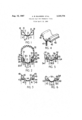
- FIGURE 1 is a diagrammatic axial cross-sectional view of part of a conventional cycle wheel
- FIGURE 2 is a diagrammatic axial cross-sectional view of part of a cycle wheel and tire assembly in accordanoe with the invention
- FIGURE 3 is a diagrammatic axial cross-sectional view of part of a cycle wheel incorporating a preferred form of sealing flap in accordance with the invention
- FIGURE 4 is a diagrammatic perspective view of part of the sealing flap shown in FIGURE 3;
- FIGURE 5 is a diagrammatic axial cross-sectional view of part of a cycle wheel incorporating an alternative form of sealing flap in accordance with the invention
- FIGURE 6 is a diagrammatic axial cross-sectional view of part of a cycle wheel incorporating a further alternative form of sealing flap in accordance with the invention.
- the cycle wheel 10 illustrated in FIGURE 1 is of a well-known type.
- the rim 11 of the wheel 10 comprises a central well 12 flanked .by raised tire bead seating portions 13 and bead retaining flanges 14. Spokes 15 are attached adjacent the center line of the rim.
- FIGURE 2 A cycle wheel in accordance with the invention is shown in FIGURE 2.
- the rim 21 is produced from a flat strip of sheet steel by circling the strip and welding its ends together to form a cylindrical blank, and rolling the blank between cooperating pairs of profiled rollers to shape the blank into a rim having the desired axial cross-sectional profile.
- the finished rim 21 is provided with a circumferentiallyextending well 22 in its central region flanked by seating portions 23 extending in a generally axial direction between the well and the tire bead retaining flanges 24.
- the axially outer sides of the flanges 24 are formed by turning the side portions 25 of the blank in a radially outwards direction, the outer parts of the radially-outwardly turned portions then being turned back radially inwardly to form the inner sides 26 of the flanges 24.
- the rim is drilled in the usual manner to receive spokes 27 and a tire inflation valve adaptor (not shown).
- the metal rim 21 thus formed has a central circumferential well 22 but is not provided with the usual beadseats spaced at a substantially radial distance beyond the base of the well (see bead seats 13 in FIGURE 1). Instead, a rubber sealing flap 28 is fitted around the rim, the axial cross-sectional profile of the rubber flap being such as to provide bead-seating portions 30 at the required radial distance from the base of the well 22.
- the rubber flap 28 is made from circled and joined extruded strip having a cross-scction which is relatively thick in its side regions 29, to provide the bead-seating portions 30, and relatively thin in its central region 31 so that it will .form a well which will fit closely within the well 22 formed in the metal rim and will not substantially increase the diameter of the well 22.
- a tubeless pneumatic tire 32 is fitted to the wheel 20 with the tire beads 33 supported on the bead seats 30 provided by the thick side portions 29 of the rubber flap 28.
- the tire 32 is inflatable through an inflation valve (not shown) fitted into an adaptor secured to the flap, the flap 28 being arranged to seal the inflation chamber of the tire.
- a wheel of a similar kind to that shown in FIG- URE 2 is provided with a rim 41 and a rubber sealing flap 42.
- the flap 42 is provided with a pair of axially outwardly projecting lips 43 which are engaged beneath the radially inner edges 44 of the axially inner sides 45 of the rim flanges 46, and an inflation valve adaptor 47 is secured to the flap as shown in FIGURE 4.
- the engagement of the lips 43 beneath the edges 44 provides an effective means for preventing disturbance of the flap during removal and fitting of the associated tire.
- FIGURE 5 a flap 50 is shown in which the relatively thick side portions 51 are each formed with a continuous internal annular cavity 52.
- the wall separating each cavity 52 from the inflation chamber of the associated tire may be perforated as indicated by references 53 to enable air pressure within the tire to be communicated to the interior of the cavities and thus to improve the rigidity of the side portions.
- Lips 54 serve to engage beneath the edges 55 of the inner walls 56 of therim flanges 57 to hold the flap in position.
- a flap 60 has relatively thick side portions 61 which have an arched profile adapted to provide cavities 62 between the side portions of the flap and the seating portions 63 of the associated wheel rim 64.
- the sealing flap and rim construction described above have the advantage that they enable a tubeless tire 32 to be used on a spoked wheel, such as a cycle wheel, having a well-base rim.
- the complex cross-sectional profile of the rim assembly is provided partly by the metal rim and partly by the rubber flap.
- an inner tube of conventional form could be used in conjunction with the rubber flap; in this arrangement the flap would not need to provide a seal, but would still have the advantage that it would enable a relatively simple rim to be used.
- a sealing flap for an open-bellied pneumatic pressure containing tire comprising an impervious flexible annular member proportioned to fit around and lie sealingly against an associated wheel rim, said annular member having a substantial thickness at each of the opposite sides thereof to provide a pair of head seats disposed radially outwardly at a substantial distance from the associated portions of the member engaged by said rim, a relatively thin cross section of said member which is adapted to lie against the central portion of the wheel rim to form a central region in sealing engagement with said wheel rim, and at least one axially projecting lip located along one of the side edges of said member for engagement with a coacting portion of the wheel rim.
- sealing flap and wheel rim structure in accordance with claim 1 including a doubled back side flange of said rim which terminates short of the opposing wheel rim, said lip being dimensioned to extend into the space between the wheel rim and the end of the doubled back side flange.
- sealing flap in accordance with claim 3 wherein said sealing flap portions, which are of substantial thickness, each includes at least one internal cavity.
- each of said cavities extends continuously around the entire circumference between the flap and its opposed r1111.
- a wheel and rim assembly comprising a pair of laterally spaced tire bead retaining flanges and a central well, a flap of relatively thin cross section conformably fitted to the profile of the central well in said rim and including a pair of axially outwardly projecting lips extending on each of opposite sides of said flap, and two bead seat portions disposed one at each side of said flap in flanking relation with said central Well and adapted to bear sealingly against said tire bead retaining flanges to provide a pair of bead seals at the outer annular surfaces thereof, said projecting lips being extended from said bead seats into sealing relation with said rim.
Description
9 1967 y A. B. BLAGDEN ETAL 3,335,778
SEALING FLAP FOR PNEUMATIC TIRES 7 Filed April 12, 1965 United States Patent 3,335,778 SEALING FLAP FOR PNEUMATIC TIRES Arthur B. Blagden, Coventry, and George E. Adams,
Kenilworth, England, assignors to Dunlop Rubber Company Limited, London, England, a corporation of Great Britain Filed Apr. 12, 1965, Ser. No. 447,452 Claims priority, application Great Britain, Apr. 18, 1964, 16,175/64 8 Claims. (Cl. 152-366) This invention relates to wheel and rim assemblies for pneumatic tires, and particularly to scaling flaps for use in assemblies which comprise an open-bellied tubeless pneumatic tire mounted on a non-airtight rim such as a rim fitted to a spoked cycle wheel or other such vehicles.
According to one aspect of the invention, a sealing flap for an open-bellied pneumatic tire comprises an annulus of rubber or plastic material for fitting around an associated wheel :rim, the annulus having an axial cross-sectional profile which is of substantial thickness at the sides thereof to provide, in the assembled state of the flap on a rim, a pair of bead seats which are spaced radially outwardly at a substantial distance from associated seating portions of the rim, and the said profile being relatively thin in the central region thereof to form a central well in the said assembled state.
According to another aspect of the invention, a rim assembly comprises a rigid rim having a pair of tire bead retaining flanges and a flap of rubber or plastic material fitted around the rim, the flap having an axial cross-sectional profile which is of substantial thickness at the sides thereof to provide a pair of bead seats spaced radially outwardly at a substantial distance from the underlying seating portions of the rim, and the said profile being relatively thin in the central region thereof to form a central well.
The invention also provides a wheel assembly comprising a wheel having a rim provided with a sealing flap as defined above.
Four embodiments of the invention will now be described with reference to the accompanying drawings, in which:
FIGURE 1 is a diagrammatic axial cross-sectional view of part of a conventional cycle wheel;
FIGURE 2 is a diagrammatic axial cross-sectional view of part of a cycle wheel and tire assembly in accordanoe with the invention;
FIGURE 3 is a diagrammatic axial cross-sectional view of part of a cycle wheel incorporating a preferred form of sealing flap in accordance with the invention;
FIGURE 4 is a diagrammatic perspective view of part of the sealing flap shown in FIGURE 3;
FIGURE 5 is a diagrammatic axial cross-sectional view of part of a cycle wheel incorporating an alternative form of sealing flap in accordance with the invention;
FIGURE 6 is a diagrammatic axial cross-sectional view of part of a cycle wheel incorporating a further alternative form of sealing flap in accordance with the invention.
The cycle wheel 10 illustrated in FIGURE 1 is of a well-known type. The rim 11 of the wheel 10 comprises a central well 12 flanked .by raised tire bead seating portions 13 and bead retaining flanges 14. Spokes 15 are attached adjacent the center line of the rim.
A cycle wheel in accordance with the invention is shown in FIGURE 2. The rim 21 is produced from a flat strip of sheet steel by circling the strip and welding its ends together to form a cylindrical blank, and rolling the blank between cooperating pairs of profiled rollers to shape the blank into a rim having the desired axial cross-sectional profile.
"Ice
The finished rim 21 is provided with a circumferentiallyextending well 22 in its central region flanked by seating portions 23 extending in a generally axial direction between the well and the tire bead retaining flanges 24. The axially outer sides of the flanges 24 are formed by turning the side portions 25 of the blank in a radially outwards direction, the outer parts of the radially-outwardly turned portions then being turned back radially inwardly to form the inner sides 26 of the flanges 24. r
The rim is drilled in the usual manner to receive spokes 27 and a tire inflation valve adaptor (not shown).
The metal rim 21 thus formed has a central circumferential well 22 but is not provided with the usual beadseats spaced at a substantially radial distance beyond the base of the well (see bead seats 13 in FIGURE 1). Instead, a rubber sealing flap 28 is fitted around the rim, the axial cross-sectional profile of the rubber flap being such as to provide bead-seating portions 30 at the required radial distance from the base of the well 22.
The rubber flap 28 is made from circled and joined extruded strip having a cross-scction which is relatively thick in its side regions 29, to provide the bead-seating portions 30, and relatively thin in its central region 31 so that it will .form a well which will fit closely within the well 22 formed in the metal rim and will not substantially increase the diameter of the well 22.
A tubeless pneumatic tire 32 is fitted to the wheel 20 with the tire beads 33 supported on the bead seats 30 provided by the thick side portions 29 of the rubber flap 28. The tire 32 is inflatable through an inflation valve (not shown) fitted into an adaptor secured to the flap, the flap 28 being arranged to seal the inflation chamber of the tire.
In the preferred construction shown in FIGURES 3 and 4, a wheel of a similar kind to that shown in FIG- URE 2 is provided with a rim 41 and a rubber sealing flap 42. The flap 42 is provided with a pair of axially outwardly projecting lips 43 which are engaged beneath the radially inner edges 44 of the axially inner sides 45 of the rim flanges 46, and an inflation valve adaptor 47 is secured to the flap as shown in FIGURE 4.
The engagement of the lips 43 beneath the edges 44 provides an effective means for preventing disturbance of the flap during removal and fitting of the associated tire.
In FIGURE 5 a flap 50 is shown in which the relatively thick side portions 51 are each formed with a continuous internal annular cavity 52. The wall separating each cavity 52 from the inflation chamber of the associated tire may be perforated as indicated by references 53 to enable air pressure within the tire to be communicated to the interior of the cavities and thus to improve the rigidity of the side portions. Lips 54 serve to engage beneath the edges 55 of the inner walls 56 of therim flanges 57 to hold the flap in position.
In the arrangement shown in FIGURE 6 a flap 60 has relatively thick side portions 61 which have an arched profile adapted to provide cavities 62 between the side portions of the flap and the seating portions 63 of the associated wheel rim 64.
The sealing flap and rim construction described above have the advantage that they enable a tubeless tire 32 to be used on a spoked wheel, such as a cycle wheel, having a well-base rim.
Further, the complex cross-sectional profile of the rim assembly is provided partly by the metal rim and partly by the rubber flap. This results in a considerable simplification in the manufacture of the metal rim, enabling it to be produced more cheaply and easily than conventional rims in which the whole profile has to be formed by difficult and costly rolling operations on the metal blank. If desired, an inner tube of conventional form could be used in conjunction with the rubber flap; in this arrangement the flap would not need to provide a seal, but would still have the advantage that it would enable a relatively simple rim to be used.
An additional advantage in using a rim construction as described above is that the spokes can be located at points spaced at a substantial distance from the center line of the rim, thus providing a wheel of greater lateral stiffness. In the conventional bicycle wheel rim shown in FIGURE 1 of the drawings the profile is obtained by using a hollow-walled construction in the regions remote from the rim center line, and the relatively steep curvature of the radially outer wall makes it necessary to position the spokes closely adjacent to the center line. Although the present invention has been illustrated and described in connection with a few selective example embodiments it will be understood that these are illustrative of the invention and are by no means restrictive thereof. It is reasonably to be assumed that those skilled in the art can make numerous revisions and adaptations of the invention and it is intended that such revisions and variation will be included within the scope of the following claims.
Having now described our invention, what we claim is:
1. A sealing flap for an open-bellied pneumatic pressure containing tire comprising an impervious flexible annular member proportioned to fit around and lie sealingly against an associated wheel rim, said annular member having a substantial thickness at each of the opposite sides thereof to provide a pair of head seats disposed radially outwardly at a substantial distance from the associated portions of the member engaged by said rim, a relatively thin cross section of said member which is adapted to lie against the central portion of the wheel rim to form a central region in sealing engagement with said wheel rim, and at least one axially projecting lip located along one of the side edges of said member for engagement with a coacting portion of the wheel rim.
2. The sealing flap and wheel rim structure in accordance with claim 1 including a doubled back side flange of said rim which terminates short of the opposing wheel rim, said lip being dimensioned to extend into the space between the wheel rim and the end of the doubled back side flange.
3. The sealing flap in accordance with claim 2 wherein said projecting lip is provided around the entire circumference of said flap.
4. A sealing flap in accordance with claim 3 wherein said sealing flap portions, which are of substantial thickness, each includes at least one internal cavity.
5. A sealing flap in accordance with claim 4 wherein said cavity extends through an entire circumference of said flap.
6. The sealing flap in accordance with claim 1 wherein said flap is of arcuate cross section to be of a configuration projecting away from sealing relation with the opposed tire rim to provide a cavity between each arched side portion of said flap and the associated seating portion of the rim.
7. The sealing flap in accordance with claim 1 wherein each of said cavities extends continuously around the entire circumference between the flap and its opposed r1111.
8. A wheel and rim assembly comprising a pair of laterally spaced tire bead retaining flanges and a central well, a flap of relatively thin cross section conformably fitted to the profile of the central well in said rim and including a pair of axially outwardly projecting lips extending on each of opposite sides of said flap, and two bead seat portions disposed one at each side of said flap in flanking relation with said central Well and adapted to bear sealingly against said tire bead retaining flanges to provide a pair of bead seals at the outer annular surfaces thereof, said projecting lips being extended from said bead seats into sealing relation with said rim.
References Cited FOREIGN PATENTS 187,816 2/1955 Austria.
991,853 6/1951 France. 1,002,210 2/1957 Germany.
243,659 12/ 1925 Great Britain.
ARTHUR L. LA POINT, Primary Examiner. C. W. HAEFELE, Assistant Examiner,
Claims (1)
1. A SEALING FLAP FOR AN OPEN-BELLIED PNEUMATIC PRESSURE CONTAINING TIRE COMPRISING AN IMPERVIOUS FLEXIBLE ANNULAR MEMBER PROPORTIONAL TO FIT AROUND AND LIE SEALINGLY AGAINST AN ASSOCIATED WHEEL RIM, SAID ANNULAR MEMBER HAVING A SUBSTANTIAL THICKNESS AT EACH OF THE OPPOSITE SIDES THEREOF TO PROVIDE A PAIR OF BEAD SEATS DISPOSED RADIALLY OUTWARDLY AT A SUBSTANTIAL DISTANCE FROM THE ASSOCIATED PORTIONS OF THE MEMBER ENGAGED BY SAID RIM, A RELATIVELY THIN CROSS SECTION OF SAID MEMBER WHICH IS ADAPTED TO LIE AGAINST THE CENTRAL PORTION OF THE WHEEL RIM TO FORM A CENTRAL REGION IN SEALING ENGAGEMENT WITH SAID WHEEL RIM, AND AT LEAST ONE AXIALLY PROJECTING LIP LOCATED ALONG ONE OF THE SIDE EDGES OF SAID MEMBER FOR ENGAGEMENT WITH A COACTING PORTION OF THE WHEEL RIM.
Applications Claiming Priority (1)
| Application Number | Priority Date | Filing Date | Title |
|---|---|---|---|
| GB16175/64A GB1098032A (en) | 1964-04-18 | 1964-04-18 | Improvements in or relating to wheel and rim assemblies for pneumatic tyres |
Publications (1)
| Publication Number | Publication Date |
|---|---|
| US3335778A true US3335778A (en) | 1967-08-15 |
Family
ID=10072542
Family Applications (1)
| Application Number | Title | Priority Date | Filing Date |
|---|---|---|---|
| US447452A Expired - Lifetime US3335778A (en) | 1964-04-18 | 1965-04-12 | Sealing flap for pneumatic tires |
Country Status (5)
| Country | Link |
|---|---|
| US (1) | US3335778A (en) |
| BE (1) | BE662654A (en) |
| ES (1) | ES311900A1 (en) |
| GB (1) | GB1098032A (en) |
| NL (1) | NL6504618A (en) |
Cited By (11)
| Publication number | Priority date | Publication date | Assignee | Title |
|---|---|---|---|---|
| US4108232A (en) * | 1976-10-28 | 1978-08-22 | The Goodyear Tire & Rubber Company | Shield for sealing a tubeless tire on a spoked wheel rim |
| EP0616911A2 (en) * | 1993-03-26 | 1994-09-28 | Jorge Nadal Aloy | Arrangement for inflating tubeless wheels |
| US6019149A (en) * | 1999-09-08 | 2000-02-01 | Stringer; Raymond E. | Wheel seal and method |
| DE102004055892A1 (en) * | 2004-11-19 | 2006-05-24 | Ktm-Sportmotorcycle Ag | Spoked wheel rim for tubeless tires |
| US20070029869A1 (en) * | 2005-08-05 | 2007-02-08 | Shimano, Inc. | Bicycle rim |
| US7445034B1 (en) * | 2007-01-17 | 2008-11-04 | Yu-Shan Huang | Bicycle wheel without an inner tire |
| DE102008058812A1 (en) * | 2008-11-24 | 2010-05-27 | Behr Industry Reichenbach Gmbh | Rim for a spoked wheel |
| US20110121637A1 (en) * | 2009-10-27 | 2011-05-26 | Hutchinson | Spoked Wheel Rim, Mounted Assembly Incorporating It and Its Method of Assembly |
| US20170190211A1 (en) * | 2013-09-19 | 2017-07-06 | Hed Cycling Products, Inc. | Bicycle Rim for Tubeless Tire |
| US10052911B2 (en) * | 2015-12-07 | 2018-08-21 | Enve Composites, Llc | Rim strip for bicycle rim |
| US10596850B2 (en) * | 2015-12-07 | 2020-03-24 | Enve Composites, Llc | Rim strip for bicycle rim |
Families Citing this family (2)
| Publication number | Priority date | Publication date | Assignee | Title |
|---|---|---|---|---|
| DE3709651A1 (en) * | 1986-04-09 | 1987-11-05 | Ronneburg Fahrzeugzubehoer | WHEEL TIRE SYSTEM FOR VEHICLES |
| TW363529U (en) * | 1998-02-12 | 1999-07-01 | Alex Machine Ind Co Ltd | Bicycle rim which can receive spokes on both side |
Citations (4)
| Publication number | Priority date | Publication date | Assignee | Title |
|---|---|---|---|---|
| GB243659A (en) * | 1925-01-06 | 1925-12-03 | Claude Eugene Goodyear | Improvements in or relating to wheels, such as road wheels of vehicles, and to the manufacture thereof |
| FR991853A (en) * | 1949-05-20 | 1951-10-11 | Sarl Lefol & Cie | Removable rim tape |
| AT187816B (en) * | 1955-02-02 | 1956-11-26 | Michael Gayer | Seal for tubeless tires |
| DE1002210B (en) * | 1955-03-26 | 1957-02-07 | Manfred Juengling | Insert for tubeless tires |
-
0
- BE BE662654D patent/BE662654A/xx unknown
-
1964
- 1964-04-18 GB GB16175/64A patent/GB1098032A/en not_active Expired
-
1965
- 1965-04-12 US US447452A patent/US3335778A/en not_active Expired - Lifetime
- 1965-04-12 NL NL6504618A patent/NL6504618A/xx unknown
- 1965-04-15 ES ES0311900A patent/ES311900A1/en not_active Expired
Patent Citations (4)
| Publication number | Priority date | Publication date | Assignee | Title |
|---|---|---|---|---|
| GB243659A (en) * | 1925-01-06 | 1925-12-03 | Claude Eugene Goodyear | Improvements in or relating to wheels, such as road wheels of vehicles, and to the manufacture thereof |
| FR991853A (en) * | 1949-05-20 | 1951-10-11 | Sarl Lefol & Cie | Removable rim tape |
| AT187816B (en) * | 1955-02-02 | 1956-11-26 | Michael Gayer | Seal for tubeless tires |
| DE1002210B (en) * | 1955-03-26 | 1957-02-07 | Manfred Juengling | Insert for tubeless tires |
Cited By (20)
| Publication number | Priority date | Publication date | Assignee | Title |
|---|---|---|---|---|
| US4108232A (en) * | 1976-10-28 | 1978-08-22 | The Goodyear Tire & Rubber Company | Shield for sealing a tubeless tire on a spoked wheel rim |
| EP0616911A2 (en) * | 1993-03-26 | 1994-09-28 | Jorge Nadal Aloy | Arrangement for inflating tubeless wheels |
| EP0616911A3 (en) * | 1993-03-26 | 1995-05-24 | Aloy Jorge Nadal | Arrangement for inflating tubeless wheels. |
| US6019149A (en) * | 1999-09-08 | 2000-02-01 | Stringer; Raymond E. | Wheel seal and method |
| DE102004055892B4 (en) * | 2004-11-19 | 2010-12-09 | Ktm-Sportmotorcycle Ag | Spoked wheel rim for tubeless tires |
| DE102004055892A1 (en) * | 2004-11-19 | 2006-05-24 | Ktm-Sportmotorcycle Ag | Spoked wheel rim for tubeless tires |
| US20060108041A1 (en) * | 2004-11-19 | 2006-05-25 | Ktm Sportmotorcycle Ag | Spoke wheel rim for tubeless tires |
| WO2006053736A2 (en) | 2004-11-19 | 2006-05-26 | Ktm Sportmotorcycle Ag | Spoke wheel rim for tubeless tyres |
| US7487811B2 (en) | 2004-11-19 | 2009-02-10 | Ktm Sportmotorcycle Ag | Spoke wheel rim for tubeless tires |
| US20070029869A1 (en) * | 2005-08-05 | 2007-02-08 | Shimano, Inc. | Bicycle rim |
| US7445034B1 (en) * | 2007-01-17 | 2008-11-04 | Yu-Shan Huang | Bicycle wheel without an inner tire |
| DE102008058812A1 (en) * | 2008-11-24 | 2010-05-27 | Behr Industry Reichenbach Gmbh | Rim for a spoked wheel |
| US20110121637A1 (en) * | 2009-10-27 | 2011-05-26 | Hutchinson | Spoked Wheel Rim, Mounted Assembly Incorporating It and Its Method of Assembly |
| US8544514B2 (en) * | 2009-10-27 | 2013-10-01 | Hutchinson | Spoked wheel rim, mounted assembly incorporating it and its method of assembly |
| US20170190211A1 (en) * | 2013-09-19 | 2017-07-06 | Hed Cycling Products, Inc. | Bicycle Rim for Tubeless Tire |
| US10189303B2 (en) | 2013-09-19 | 2019-01-29 | Hed Cycling Products, Inc. | Bicycle rim for tubeless tire |
| US10703133B2 (en) * | 2013-09-19 | 2020-07-07 | Hed Cycling Products, Inc. | Bicycle rim for tubeless tire |
| US10967675B2 (en) * | 2013-09-19 | 2021-04-06 | Hed Cycling Products, Inc. | Bicycle rim for tubeless tire |
| US10052911B2 (en) * | 2015-12-07 | 2018-08-21 | Enve Composites, Llc | Rim strip for bicycle rim |
| US10596850B2 (en) * | 2015-12-07 | 2020-03-24 | Enve Composites, Llc | Rim strip for bicycle rim |
Also Published As
| Publication number | Publication date |
|---|---|
| ES311900A1 (en) | 1966-05-16 |
| NL6504618A (en) | 1965-10-19 |
| GB1098032A (en) | 1968-01-03 |
| BE662654A (en) |
Similar Documents
| Publication | Publication Date | Title |
|---|---|---|
| US2698042A (en) | Air-sealing tire liner | |
| US3335778A (en) | Sealing flap for pneumatic tires | |
| US3965957A (en) | Vehicle wheel structure | |
| US4293017A (en) | Dual-chamber pneumatic tire | |
| US2844180A (en) | Safety rim structure | |
| US4289186A (en) | Sealing means for pneumatic tire and wheel rim assemblies | |
| US3047041A (en) | Pneumatic tire with integral rim | |
| US3669174A (en) | Wheels | |
| US4408647A (en) | Vehicle wheel | |
| US2198978A (en) | Rim construction | |
| US2840133A (en) | Tubeless tire and rim assembly | |
| US3161219A (en) | Multi-compartment vehicle tire | |
| US3025898A (en) | Safety wheel rim | |
| US3895668A (en) | Pneumatic wheel | |
| US2754876A (en) | Safety tire | |
| US2537442A (en) | Air-cooled vehicle wheel | |
| IL45361A (en) | Wheel rims | |
| US2405954A (en) | Wheel | |
| US2811189A (en) | Pneumatic tire | |
| US2884983A (en) | Safety pneumatic tire wheel | |
| US2664935A (en) | Large volume multichamber tire | |
| US2027282A (en) | Tire and rim | |
| US4157106A (en) | Run-flat tire having internal support means | |
| GB2044189A (en) | Improvements in or relating to sealing means for pneumatic tyre and wheel rim assemblies | |
| US2731062A (en) | Tubeless tire |