US3330910A - Formant analysis and speech reconstruction - Google Patents
Formant analysis and speech reconstruction Download PDFInfo
- Publication number
- US3330910A US3330910A US365353A US36535364A US3330910A US 3330910 A US3330910 A US 3330910A US 365353 A US365353 A US 365353A US 36535364 A US36535364 A US 36535364A US 3330910 A US3330910 A US 3330910A
- Authority
- US
- United States
- Prior art keywords
- speech
- frequency
- formant
- signal
- wave
- Prior art date
- Legal status (The legal status is an assumption and is not a legal conclusion. Google has not performed a legal analysis and makes no representation as to the accuracy of the status listed.)
- Expired - Lifetime
Links
- 238000004458 analytical method Methods 0.000 title description 3
- 238000001228 spectrum Methods 0.000 claims description 17
- 230000006835 compression Effects 0.000 claims description 10
- 238000007906 compression Methods 0.000 claims description 10
- 230000006870 function Effects 0.000 description 20
- 230000001755 vocal effect Effects 0.000 description 16
- 230000005284 excitation Effects 0.000 description 14
- 230000005540 biological transmission Effects 0.000 description 10
- 238000012546 transfer Methods 0.000 description 9
- 239000003990 capacitor Substances 0.000 description 8
- 238000013016 damping Methods 0.000 description 7
- 239000003550 marker Substances 0.000 description 6
- 238000010586 diagram Methods 0.000 description 5
- 238000012512 characterization method Methods 0.000 description 3
- 238000004891 communication Methods 0.000 description 3
- 238000013461 design Methods 0.000 description 3
- 230000003595 spectral effect Effects 0.000 description 3
- 230000003466 anti-cipated effect Effects 0.000 description 2
- 238000010276 construction Methods 0.000 description 2
- 238000000034 method Methods 0.000 description 2
- 230000002194 synthesizing effect Effects 0.000 description 2
- 238000012937 correction Methods 0.000 description 1
- 238000009795 derivation Methods 0.000 description 1
- 238000011161 development Methods 0.000 description 1
- 238000007599 discharging Methods 0.000 description 1
- 210000004704 glottis Anatomy 0.000 description 1
- 230000010354 integration Effects 0.000 description 1
- 238000005259 measurement Methods 0.000 description 1
- 230000008447 perception Effects 0.000 description 1
- 238000012545 processing Methods 0.000 description 1
- 230000005855 radiation Effects 0.000 description 1
- 238000012360 testing method Methods 0.000 description 1
- 230000001960 triggered effect Effects 0.000 description 1
- 210000001260 vocal cord Anatomy 0.000 description 1
Images


Classifications
-
- G—PHYSICS
- G10—MUSICAL INSTRUMENTS; ACOUSTICS
- G10L—SPEECH ANALYSIS OR SYNTHESIS; SPEECH RECOGNITION; SPEECH OR VOICE PROCESSING; SPEECH OR AUDIO CODING OR DECODING
- G10L19/00—Speech or audio signals analysis-synthesis techniques for redundancy reduction, e.g. in vocoders; Coding or decoding of speech or audio signals, using source filter models or psychoacoustic analysis
Definitions
- This invention relates to bandwidth compression systems, and in particular to the transmission of speech information over narrow bandwidth media in coded form.
- Conventional speech communications systems convey human speech by transmitting an electrical facsimile of the acoustic waveform produced by human talkers. It has been recognized, however, that facsimile transmission of the speech waveform is a relatively inefficient way to transmit speech information, because of the redundancy of human speech. That is, the amount of information contained in a typical speech wave may be transmitted over a communication channel of substantially narrower bandwidth than that required for facsimile transmission of the speech waveform. In order to make more economic use of the frequency bandwidth of transmission media, a number of bandwidth compression arrangements have been devised for transmitting the information content of a speech wave over a channel whose bandwidth is substantially narrower than that required for transmission of the speech waveform.
- Bandwidth compression systems typically include at a transmitter terminal an analyzer for deriving from an incoming speech wave a group of relatively narrow-band control signals representative of selected informationbearing characteristics of the speech wave and at a receiver terminal, a synthesizer for reconstructing from the control signals a replica of the original speech wave.
- the distinctive speech characteristics represented by the control signals are the frequencies and amplitudes of the so-called formants or normal modes of vibration of the vocal tract.
- Descriptions of formant vocoders may be found in H. L. Barney Patent- 2,819,341, issued Jan. 7, 1958 and in an article by J. L. Flanagan entitled Note on the Design of Terminal-Analog Speech Synthesizers, volume 29, Journal of the Acoustical Society of America, page 306 (1957).
- the conventional formant vocoder is relatively eflicient from the standpoint of transmitting information, the replica speech wave reconstructed from the transmitted control signals does not sound as natural as speech transmitted by facsimile waveform systems.
- the bandwidth compression system of the present invention may also be characterized as a formant vocoder but it attempts to improve the quality of the replica speech wave by encoding a set of variables which more accurately describe the speech formants.
- the transmission properties of the human vocal tract may be characterized as a superposition of damped sinusoids, each sinusoid corresponding to one of the formants of the vocal tract.
- the present invention recognizes that the sinusoid characterization of speech formants provides a precise characterization of the transmission properties of the human vocal tract, but in order to achieve an improvement in quality without reducing bandwith economy by too large a factor, each sinusoid is approximated in the present inven- 3,330,910 Patented July 11, 1967 tion by assuming a predetermined constant value for the formant damping variable and by measuring the three other variables.
- the information content of a speech wave is encoded in this invention in terms of a group of 3 -N control signals, where N is an integer representing the number of formants or damped sinusoids to be employed in describing the transmission properties of the vocal tract.
- the three parameters selected in the present invention to represent each sinusoid are the formant frequency and the magnitude and phase angle of the formant residue, a different residue being associated with each formant.
- the frequencies of a selected group of formants are located, after which a measure of the magnitude and phase angle of the residue associated with each formant is obtained from the magnitude and phase angle of the harmonic component of the speech amplitude spectrum which is determined to be closest in frequency to each formant being represented.
- Each of these three parameter is represented by a relatively narrow bandwidth control signal, and together with socalled voiced-unvoiced and pitch control signals representative of the properties of the excitation applied to the vocal tract, these control signals represent in coded form the information content of the incoming speech wave.
- control signals are transmitted over a reduced bandwidth channel to a receiver station, where there is generated from the control signals a group of damped sinusoids corresponding to the selected group of formants whose frequencies are located at the transmitter terminal. This group of sinusoids is then combined to form a natural sounding replica of the original speech wave.
- FIG. 1 is a block diagram showing the transmitter terminal of this invention
- FIG. 2 is a block diagram illustrating the receiver terminal of this invention
- FIG. 3 is a block diagram illustrating in detail certain components of the system shown in FIG. 1;
- FIG. 4 is a diagram illustrating in detail certain other components of the transmitter terminal shown in FIG. 1;
- FIGS. 5A and 5B are graphic illustrations of assistance in explaining the operation of the present invention.
- FIG. 6 is a diagram showing in detail still other components of the transmitter terminal in FIG. 1.
- Theoretical considerations The transmission properties of the human vocal tract may be described by taking the ratio of the Laplace transform, U (s), of the volume velocity of air through the lips, u (t), to the Laplace transform, U (s), of the volume velocity of air through the vocal cords or glottis, u (t), this ratio being commonly known as the transfer characteristic or transfer function of the vocal tract.
- the ratio of the Laplace transform, U (s), of the volume velocity of air through the lips, u (t), to the Laplace transform, U (s), of the volume velocity of air through the vocal cords or glottis, u (t) this ratio being commonly known as the transfer characteristic or transfer function of the vocal tract.
- Equation 1 Equation 1
- Equation 2 may also be written in terms of a partial fraction expansion that is formally the same for both vowel sounds and nonvowel sounds,
- the quantity denoted A is called the complex residue in the pole s and is a function of all of the s s. That is, for vowel sounds, the residue A in the mth pole, s may be Written whereas for nonvowel sounds the residue A in the mth pole, s may be written
- Both vowel and nonvowel sounds are therefore completely represented by (4k) quantities, where k is an integer denoting the number of formants or poles to be represented.
- k is an integer denoting the number of formants or poles to be represented.
- k is an integer denoting the number of formants or poles to be represented.
- formant bandwidth, a plays a relatively small role in influencing speech quality, hence only three of these four quantities are encoded in the present invention for each formant to be represented, namely, the magnitude and phase angle of each residue and the formant frequency.
- the bandwidth of each formant may be measured and encoded, if desired, with a consequent increase in the frequency bandwidth required for transmission of all of the coded signals.
- the formant frequency may be determined by any one of a number of well-known techniques; for example, see H. L. Barney Patent 2,819,- 341, issued Jan. 7, 1958.
- the derivation of a pair of coded control signals representative of the magnitude and phase angle of each formant residue is based upon the following approximations.
- A is approximately equal to the maximum of the speech amplitude spectrum lE l, at the frequency w of the kth formant, that is,
- FIG. 5A shows an idealized version of a voiced speech sound spectrum having an envelope with several maxima, IE I, [E
- the present invention approximates the residue magnitudes and phase angles by determining the amplitudes and phase angles of the speech frequency components which are nearest in frequency to the spectral maxima corresponding to speech formants.
- the magnitudes of the Fourier coefficients F(nw constitute the amplitude spectrum of )(t), and may be obtained by rewriting Equation 8b in terms of sine and cosine functions so that the magnitude or absolute value of F(nw is given by [L JKU sin (00061151113 Equations 10a and 10b therefore specify that in order to obtain the magnitude of the nth harmonic component of the speech amplitude spectrum, it is necessary to multiply the incoming speech wave f(t) by cos (ne t) and sin (ne t) respectively, integrate the products f(t) cos (nw t) and f(t) sin (nw t) over the period T, square each of the integrated products, and determine the square root of the sum of the squared integrated products. It is this square root which is employed in the present invention to represent the residue magnitude, [A
- phase angle of the nth harmonic component may be derived from the relationship in Equation 10a, which may be rewritten where a represents the real (Re) part of F(nw and b represents the imaginary (Im) part of F(nw so that the phase angle t is given by the expression I: -In;E a..
- FIG. 1 illustrates the transmitter terminal of a speech bandwidth compression system embodying the principles of this invention.
- An incoming speech signal denoted f(t) from source 10 which may be a conventional microphone of any desired construction, is applied simultaneously to formant frequency detector 100, pitch detector 101, and through delay element 11 to formant residue analyzers 102-1 through 102-N.
- Formant frequency detector 100 may be any one of a number of well-known arrangements for determining the frequencies of selected speech formants; for example, detector 100 may be of the type described in H. L. Barney Patent 2,819,341, issued Jan.
- a typical choice for N is 3 so that detector 100 develops three formant frequency control signals representative of the frequency locations of the first three speech formants, it being understood that addi- 1,0,, tan
- Pitch detector 101 which may also be of well-known construction, derives from the incoming speech signal a voiced-unvoiced control signal which indicates whether the incoming speech signal represents a voiced or an unvoiced sound at a given instant, and a pitch period signal comprising a train of uniform amplitude pulses having a period T that follows the period of the speech signal.
- a suitable detector is disclosed in A. I. Prestigiacomo Patent 3,020,344, issued Feb. 6, 1962.
- Each of the formant frequency signals w through am is applied to a corresponding formant residue analyzer circuit 102-1 through 102-N, and the pitch period signal is applied directly to each analyzer 102-1 through 102-N, as well as through low-pass filter 101a.
- Filter 101a smooths or averages the uniform amplitude pulses to produce a pitch frequency signal which indicates the fundamental or pitch frequency w
- Analyzers 102-1 through 102-N are similar in structure, and hence only analyzer 102-1 is shown in detail.
- the pitch frequency signal 01 and the formant frequency control signal 01 are applied to speech harmonic generator 103, which is shown in detail in FIG. 3.
- generator 103 derives from these two control signals an output signal, denoted lt w which represents the frequency of the harmonic component of the speech amplitude spectrum which is nearest in frequency to the formant frequency w
- the output signal developed by generator 103 is delivered in parallel to sine and cosine function generators 104a and 104b, one of which is shown in detail in FIG. 4 and further described below.
- Generators 104a and 1041) are also supplied with the pitch period signal, T, and generator 104a produces an output signal comprising n cycles of a sine wave sin(n w t) generated within a single speech period of duration T seconds, while generator 104b produces an output signal comprising 11 cycles of a cosine wave c0s(n w t) generated within a single speech period of duration T seconds.
- each of the output signals of generators 104a and 10417 is multipled by the incoming speech signal (t) in multipliers 105a and 1115b to obtain product signals respectively proportional to (t) Sin(n w t) and f(t) c0S(n w t). From multipliers 105a and 10517 each of the product signals is delivered to a corresponding integrating circuit 106a and 106b respectively. As specified by Equations 11a and 11b and as shown in detail in FIG.
- circuits 106a and 1061 integrating circuits 106a and 1061; respectively derive from each of the product signals an output signal representative of the imaginary and real parts of the complex Fourier coefficient F(n w which is utilized in this invention to approximate the complex residue, A of the pole or formant located at the frequency m
- the integrated output signals of circuits 106a and 106b are sent to magnitude analyzer 107 and inverse tangent function generator 108.
- Analyzer 107 which is also shown in detail in FIG. 6, obtains an output signal representative of the magnitude of the harmonic component
- Filters 109a and 1091) may each have a cutoff frequency Z on the order of 20 to 30 cycles per second, since the vocal tract and therefore the formant residues changes relatively slowly.
- the formant frequency control signals from detector 100 and the voicedunvoiced and pitch frequency control signals from pitch detector 101 and low-pass filter 101a, respectively are transmitted over the reduced bandwidth medium to the receiver station of the present invention.
- the transmitted control signals are employed to reconstruct a natural sounding replica of the original speech signal f(t).
- each of the analyzers 102-1 through 102-N derives from the pulse train from generator 12 and from the low frequency signal from filter 101a a pair of output signals representative of the magnitude and phase angle of the short time unvoiced speech spectrum evaluated at the formant frequencies specified by the control signals al through w from detector 100.
- FIG. 2 illustrates the receiver terminal of this invention which constructs from the incoming narrow band control signals derived at the transmitter terminal a sum of N damped sinusoidal waves representing the inverse transform of the vocal tract transfer function specified by Equation 6, each sinusoidal wave corresponding to one of the N formants analyzed at the transmitter terminal. It is this sum of damped sinusoidal waves which constitutes the replica of the original speech wave reconstructed in the present invention.
- the voiced-unvoiced and pitch frequency control signals are applied to an excitation generator 201, which may comprise conventional buzz and hiss sources.
- signal generator 201 when the voiced-unvoiced control signal indicates the presence of a voiced sound in the original speech, signal generator 201 produces a train of uniform amplitude pulses have a period T specified by the pitch control signal, whereas when the voiced-unvoiced control signal indicates the presence of an unvoiced sound generator 201 produces a train of randomly occurring uniform amplitude pulses.
- the excitation signal from generator 201 is applied in parallel to formant synthesizers 202-1 through 202-N, and in addition each synthesizer is supplied with the three control signals representing the frequency, residue magnitude and residue phase angle associated with the sinusoid characterization of a particular formant. Since synthesizers 202-1 through 202-N are similar in structure and operation, only synthesizer 202-1 is shown in detail.
- Each synthesizer 202 develops one of the damped cosine waves specified by Equation 6.
- Equation 6 may be written ZIA lE C (w t-, p (13:7) and the jth term of the sum on the right-hand side of Equation 13a may be expanded by means of a trigonometric identity so that [cos (w t) cos ((pQ-Sil'l (w t) sin a -)1 (13b)
- the jth synthesizer 202-j of the present invention develops from the excitation signal produced by generation 201 and from the transmitted control signals lA l, w (Pj a damped cosine wave according to Equation 13b.
- the excitation signal from generator 201 is applied to amplitude modulator 203 together with the residue magnitude signal, [A associated with the first formant, so that the amplitude of the excitation signal is adjusted to be proportional to the instantaneous value represented by the residue magnitude signal.
- the amplitude adjusted excitation signal from modulator 203 is delivered simultaneously to variable bandpass filters 204a and 204b, which may be similar to the circuit shown in FIG. 5, of H. L. Barney Patent 2,819,341 issued Jan.
- filter 204a is suitably con- 'nected to produce a damped sine impulse response Specified by the expression e sin w t
- filter 20411 is suitably connected to produce a damped cosine impulse response specified by the expression e" cos co t.
- the quantity a is a constant selected to correspond to a desired bandwidth for the first formant and m is the variable center frequency of the filter pass band whose location on the frequency scale is controlled by the formant frequency control signal m
- the output signal of filter 204a is therefore a damped sine wave of the form lA le sin cu l, and the output signal of filter 20 1b is therefore a damped cosine wave of the form
- the damped sine wave from filter 204a is applied to multiplier 205a, and the damped cosine wave from filter 20412 is applied to multiplier 20512.
- sine function generator 206a Also connected to multiplier 205a is the output terminal of sine function generator 206a, which is responsive to the incoming narrow band (p signal and develops an output signal representative of sin (p Any desired sine function generator may be employed; for example, see pages 81-87 of the previously cited Karplus and Soroka text.
- Multiplier 205a therefore develops an output signal indicative of the product [A la sin w t-sin (p Similarly, cosine function generator 206b is responsive to the incoming narrow-band (p control signal and develops an output signal proportional to cos (p so that multiplier 20Sb generates an output signal indicative of the product
- the output signal of multiplier 205a is applied to the subtrahend or negative input terminal of subtractor 207, which may be of any well-known design, while the output signal of multiplier 2051) is applied to the minuend or positive input terminal of subtractor 207.
- the difference signal produced at the output terminal of subtractor 207 is therefore proportional to the first term in Equation 13a.
- synthesizers 202-2 through 202-N each synthesize an output signal proportional to the second through Nth terms of Equation 13a.
- the output signals of synthesizers 202-1 through 202-N are additively combined in a conventional adder 208 to form an electrical wave that closely follows the specifications provided by Equations 6 and 13a.
- Reproducer 209 converts the electrical Wave from adder 208 into a sound wave which is a natural sounding replica of the original speech sound, where reproducer 209 may be a loudspeaker of any desired variety.
- Speech harmonic generator Referring now to FIG. 3, this drawing illustrates in detail speech harmonic generator 103 shown in FIG. 1.
- the incoming fundamental pitch signal, to from filter 101a is applied to the divisor terminal of a conventional divider circuit 30, and the incoming formant frequency signal 0 is applied to the dividend terminal of divider 30.
- the formant frequency m is not an integral multiple of the fundamental pitch frequency w
- the quotient signal, denoted q represents a number lying between two integers, and k, j q k. Therefore, in order to obtain the frequency of the speech harmonic component nearest in frequency to m the present invention passes the quotient signal to a quantizer 31; for example, a quantizer of the type described in B. M. Oliver Patent 2,773,980, issued Dec. 11, 1956.
- Quantizer 31 is provided with a suitable plurality of preadjusted control level voltages corresponding to an anticipated range of values for the quotient signal from divider 30, so that the output condition of quantizer 31 signifies the value of the integer closest to the quotient signal value.
- the first formant of a typical adult male voice may occur within the frequency range from about 300 to 1,000 cycles per second, and the fundamental pitch frequency may vary from about 50 to 150 cycles per second, hence the speech harmonic nearest in frequency to the first formant frequency may be from 2 to 20 times the fundamental pitch frequency.
- quantizer 31 is provided with 19 control level voltages each corresponding to one of the integers from 2 to 20, inclusive.
- the quantizer in each of the corresponding speech harmonic generators of analyzers 102-2 through 102-N is provided with a plurality of control levels corresponding to the anticipated range of integers for the associated formant.
- Quantizer 31 is connected to one of the input terminals of multiplier 32, and the incoming fundamental pitch frequency signal is connected to the other input terminal of multiplier 32, thereby developing at the output terminal of multiplier 32 a signal representative of the frequency 71 mg, of the speech harmonic closest the formant frequency al where n represents the integer closest to q, the number represented by the quotient signal of divider 30.
- the output signal of multiplier 32 is then utilized in sine and cosine function generators 104a and 1114b in the fashion previously described.
- Sine/ cosine function generator Referring now to FIG. 4, the signal representative of the harmonic closest in frequency to the first speech formant, n w is applied to variable frequency oscillator 40, and oscillator 40 develops at its output terminal a sine wave sin n w t. This wave is then sent to multivibrator 41 which produces a square wave at radian frequency X (n 'w where the value of X need only be greater than that required by the Nyquist interval for the sine or cosine function to be generated; for example, a convenient and completely adequate number would be 10.
- This square wave causes the glow discharge of multicathode gas transfer tube 42 to step progressively from cathode K-l to cathode K-X at a rate equal to X(n w divided by 21:-
- multivibrator 43 may be of the conventional monostable or one-shot variety having a low output impedance.
- Multivibrator 43 is triggered by the incoming pitch period pulses so that the glow discharge spot is returned to cathode K-l at the beginning of each speech period. It is therefore evident that in each speech period the glow discharge in tube 42 will step through n complete cycles.
- Each cathode is connected to a common output bus 44 through a potentiometer P-1 through P-X, where each potentiometer is set at a resistance value which corresponds to a particular sine or cosine sample value within a single sine or cosine period.
- bus 44 there is developed a sequence of sine or cosine samples during each speech period, and the output terminal of bus 44 is connected to a low-pass filter 45 which smooths the sequence of Il -X samples during each period T to develop a sine or cosine wave of the form sin (n w t) or cos ("W00- Integrating circuit and magnitude analyzer
- FIG. 6 illustrates in detail an integrating circuit for performing the integration required of circuits 106a and 106b in FIG. 1 During a pitch period the incoming product signal f(t).sin n w t is applied through resistance R1 to capacitor C1, the time constant of resistor R1 and capacitor C1 being long compared to the pitch period T.
- the voltage accumulated on capacitor C1 is proportional to the integral of the incoming product signal over the pitch period.
- an incoming pitch period pulse is applied to relay 60 through delay element 62 and to relay 63, hence relay 63 is briefly energized before relay 60 so that relay 63 transfers the voltage on capacitor C1 to capacitor C2, where the capacitance of capacitor C2 is small in comparison with the capacitance of capacitor C1.
- relay 60 is briefly energized, thereby discharging capacitor C1 prior to the start of the next pitch period.
- integrating circuit 106 which is identical with integrating circuit 106a, develops from the incoming product signal f(t).cos n w t an output signal proportional to the real part of the speech amplitude spectrum at the harmonic frequency n w in accordance with Equation 110.
- Circuits 66 and 67 may be of any desired variety for obtaining an output signal proportional to the square or second power of an input signal; for example, see pages 78 through 81 of the previously mentioned Karplus and Soroka text.
- the output signals of circuits 66 and 67 are combined by adder circuit 68 and the sum signal developed at the output terminal of adder 68 is passed to square root taking circuit 69, which may also be of the type described on pages 78 through 81 of the Karplus and Soroka text.
- the output signal of circuit 69 is therefore proportional to the square root of the sum of the squares of the integrated product signals from circuits 106a and 106b, hence according to Equation 10b the output signal of circuit 69 is proportional to the magnitude of the speech amplitude spectrum at the harmonic frequency n w and in this invention this signal is employed as an approximation of the formant residue magnitude (A in the manner described above.
- a bandwidth compression system that comprises a transmitter terminal including a source of an incoming speech wave
- each of said analyzer means being supplied with said speech wave, said pitch control signal, and said corresponding formant frequency control signal,
- each of said analyzer means derives from said control signals a pair of magnitude and phase angle control signals respectively representative of the magnitude and phase angle of the harmonic component of said speech wave which is closest in frequency to the frequency of said selected maximum represented by said formant frequency control signal,
- a bandwidth compression system that comprises a transmitter terminal including a source of an incoming speech Wave
- a voicedunvoiced control signal indicative of the presence of voiced and unvoiced portions of said speech wave and a pitch control signal indicative of the periodicity of voiced portions of said speech wave
- each of said analyzer means being supplied with said speech Wave, said pitch control signal, and said corresponding formant frequency control signal,
- each of said analyzer means derives from said control signals a pair of magnitude and phase angle control signals respectively representative of the magnitude and phase angle of the harmonic component of said speech wave which is closest in frequency to the frequency of said selected maximum represented by said formant frequency control signal,
- each of said synthesizer means generates a damped sinusoidal wave representing one of the formants of said speech wave from said excitation signal, a corresponding one of said formant frequency control signals, and a corresponding one of said pairs of magnitude and phase angle signals, and
- Apparatus for synthesizing speech which comprises a source of a voiced-unvoiced control signal and a pitch control signal respectively indicative of the presence of voiced and unvoiced portions of an original speech Wave and of the periodicity of voiced portions of said speech wave,
- each group of damped sinusoid control signals including a formant frequency signal representative of the frequency of a selected formant peak in the amplitude spectrum of said speech wave, an amplitude control signal representative of the amplitude of the harmonic component of said speech wave which is closest in frequency to said formant peak, and a phase control signal representative of the phase angle of said harmonic component of said speech wave which is closest in frequency to said formant peak,
- each of said synthesizer means derives from said excitation signal and said corresponding group of damped sinusoid control signals a damped sinusoid having an amplitude, frequency, and phase angle controlled by said group of damped sinusoid control signals and a predetermined damping, and
- first detector means for deriving from said speech Wave a formant frequency signal indicative of the frequency location of a selected formant peak in the amplitude spectrum of said speech wave
- second detector means for deriving from said speech wave a train of pitch marker pulses having a period indicative of the fundamental period of voiced portions of said speech wave and a pitch frequency signal indicative of the fundamental frequency of voiced portions of said speech wave, and
- analyzer means supplied with said speech wave, said formant frequency signal, said train of pitch marker pulses, and said pitch frequency signal for deriving a pair of control signals respectively indicative of the magnitude and phase angle of the harmonic component of said speech wave which is closest in frequency to said formant peak
- said analyzer means comprising speech harmonic generator for deriving from said formant frequency signal and said pitch frequency signal an output signal proportional to the frequency of the harmonic component of said amplitude spectrum which is closest in frequency to the frequency location of said selected formant peak
- first integrating means supplied with said sine product signal and said train of pitch marker pulses for obtaining at the end of each pitch period an integrated sine product signal proportional to the integral of said sine product signal over each pitch period represented by said pitch marker pulses,
- second integrating means in parallel with said first integrating means and supplied with said cosine product signal and said train of pitch marker pulses for obtaining at the end of each pitch period an integrated cosine product signal proportional to the integral of said cosine product signal over each pitch period represented by said pitch marker pulses,
- magnitude analyzer means supplied with said integrated sine product signal and said integrated cosine product signal for obtaining a magnitude signal proportional to the square root of the sum of the second power of said integrated sine product signal and the second power of said integrated cosine product signal, and
- inverse tangent analyzer means in parallel with said magnitude analyzer means and supplied with said integrated sine product signal and said integrated cosine product signal for obtaining phase angle signal proportional to the inverse tangent of the quotient of the negative of said integrated sine product signal divided by said integrated cosine product signal,
- said magnitude signal represents the magnitude of said harmonic component which is closest in frequency to said selected formant peak and said phase angle signal represents the phase angle of said harmonic component.
- Apparatus for synthesizing a signal representative of the characteristics of a selected formant of a speech wave which comprises a source of an excitation signal comprising a train of uniform amplitude pulses having a period indicative of the presence of voiced and unvoiced portions of and original speech Wave,
- amplitude modulating means responsive to said magnitude control signal and supplied with said excitation signal for adjusting the amplitude of said train of pulses to follow the amplitude represented by said magnitude control signal
- a first variable bandpass filter responsive to said formant frequency control signal and supplied with said amplitude adjusted train of pulses, wherein said first filter has a pass band With a variable center frequency that follows the formant frequency represented by said formant frequency control signal and wherein said first filter has a predetermined damping factor so that said first filter produces a damped sinusoidal output Wave with a predetermined damping and at a frequency determined by said formant frequency control signal,
- a second variable bandpass filter in parallel with said first variable bandpass filter and responsive to said formant frequency control signal as well as supplied with said amplitude adjusted train of pulses, wherein said second filter has a pass band with a variable center frequency that follows the formant frequency represented by said formant frequency control signal and wherein said second filter has a predetermined damping factor so that said second filter produces a damped cosinusoidal output wave With -a predetermined damping and at a frequency determined by said formant frequency control signal,
- a sine function generator supplied with said phase control signal for generating a sine wave having a frequency specified by the phase angle represented by said phase angle signal
- a cosine function generator in parallel with said sine function generator and supplied with said phase control signal for generating a cosine wave having a frequency specified by the phase angle represented by said phase angle signal
- first multiplying means supplied with said damped sinusoidal output wave and said sine wave for developing a first product signal proportional to the product of said damped sinusoidal output wave and said sine wave
- second multiplying means supplied with said damped cosinusoidal output Wave and said cosine wave for developing a second product signal proportional to the product of said damped cosinusoidal output wave and said cosine Wave
Description
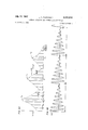
y 1957 J. L. FLANAGAN FORMANT ANALYSIS AND SPEECH RECONSTRUCTION 4 Sheets-Sheet 4 Filed May 6, 1964 United States Patent 3,330,910 FORMAVT ANALYSIS AND SPEECH RECONSTRUCTION James L. Flanagan, Warren Township, Somerset County,
N.J., assignor to Bell Telephone Laboratories, Incorporated, New York, N.Y., a corporation of New York Filed May 6, 1964, Ser. No. 365,353 5 Claims. (Cl. 179-1555) This invention relates to bandwidth compression systems, and in particular to the transmission of speech information over narrow bandwidth media in coded form.
Conventional speech communications systems, for example, telephone systems, convey human speech by transmitting an electrical facsimile of the acoustic waveform produced by human talkers. It has been recognized, however, that facsimile transmission of the speech waveform is a relatively inefficient way to transmit speech information, because of the redundancy of human speech. That is, the amount of information contained in a typical speech wave may be transmitted over a communication channel of substantially narrower bandwidth than that required for facsimile transmission of the speech waveform. In order to make more economic use of the frequency bandwidth of transmission media, a number of bandwidth compression arrangements have been devised for transmitting the information content of a speech wave over a channel whose bandwidth is substantially narrower than that required for transmission of the speech waveform. Bandwidth compression systems typically include at a transmitter terminal an analyzer for deriving from an incoming speech wave a group of relatively narrow-band control signals representative of selected informationbearing characteristics of the speech wave and at a receiver terminal, a synthesizer for reconstructing from the control signals a replica of the original speech wave.
One of the best known bandwidth compression arrangements is the so-called resonance or formant vocoder, in
which the distinctive speech characteristics represented by the control signals are the frequencies and amplitudes of the so-called formants or normal modes of vibration of the vocal tract. Descriptions of formant vocoders may be found in H. L. Barney Patent- 2,819,341, issued Jan. 7, 1958 and in an article by J. L. Flanagan entitled Note on the Design of Terminal-Analog Speech Synthesizers, volume 29, Journal of the Acoustical Society of America, page 306 (1957). Although the conventional formant vocoder is relatively eflicient from the standpoint of transmitting information, the replica speech wave reconstructed from the transmitted control signals does not sound as natural as speech transmitted by facsimile waveform systems.
The bandwidth compression system of the present invention may also be characterized as a formant vocoder but it attempts to improve the quality of the replica speech wave by encoding a set of variables which more accurately describe the speech formants. It is well known that the transmission properties of the human vocal tract may be characterized as a superposition of damped sinusoids, each sinusoid corresponding to one of the formants of the vocal tract. There are four variables that specify the characteristics of each damped sinusoid, so that in principle each formant is exactly specified by a set of four parameters; namely, the amplitude and phase angle of a quantity generally referred to as the formant residue, the formant frequency, and the formant damping or bandwidth. The present invention recognizes that the sinusoid characterization of speech formants provides a precise characterization of the transmission properties of the human vocal tract, but in order to achieve an improvement in quality without reducing bandwith economy by too large a factor, each sinusoid is approximated in the present inven- 3,330,910 Patented July 11, 1967 tion by assuming a predetermined constant value for the formant damping variable and by measuring the three other variables. Thus the information content of a speech wave is encoded in this invention in terms of a group of 3 -N control signals, where N is an integer representing the number of formants or damped sinusoids to be employed in describing the transmission properties of the vocal tract.
The three parameters selected in the present invention to represent each sinusoid are the formant frequency and the magnitude and phase angle of the formant residue, a different residue being associated with each formant. At the transmitter terminal of this invention, the frequencies of a selected group of formants are located, after which a measure of the magnitude and phase angle of the residue associated with each formant is obtained from the magnitude and phase angle of the harmonic component of the speech amplitude spectrum which is determined to be closest in frequency to each formant being represented. Each of these three parameter is represented by a relatively narrow bandwidth control signal, and together with socalled voiced-unvoiced and pitch control signals representative of the properties of the excitation applied to the vocal tract, these control signals represent in coded form the information content of the incoming speech wave. The control signals are transmitted over a reduced bandwidth channel to a receiver station, where there is generated from the control signals a group of damped sinusoids corresponding to the selected group of formants whose frequencies are located at the transmitter terminal. This group of sinusoids is then combined to form a natural sounding replica of the original speech wave.
The invention will be fully understood from the following descriptions of illustrative embodiment thereof, taken in connection with the appended drawings, in which:
FIG. 1 is a block diagram showing the transmitter terminal of this invention;
FIG. 2 is a block diagram illustrating the receiver terminal of this invention;
FIG. 3 is a block diagram illustrating in detail certain components of the system shown in FIG. 1;
FIG. 4 is a diagram illustrating in detail certain other components of the transmitter terminal shown in FIG. 1;
FIGS. 5A and 5B are graphic illustrations of assistance in explaining the operation of the present invention; and
FIG. 6 is a diagram showing in detail still other components of the transmitter terminal in FIG. 1.
Theoretical considerations The transmission properties of the human vocal tract may be described by taking the ratio of the Laplace transform, U (s), of the volume velocity of air through the lips, u (t), to the Laplace transform, U (s), of the volume velocity of air through the vocal cords or glottis, u (t), this ratio being commonly known as the transfer characteristic or transfer function of the vocal tract. As shown by J. L. Flanagan and A. S. House in Development and Testing of a Formant-Coding Speech Compression System, vol. 28, Journal of the Acoustical Society of America, page 1099 (1956), the vocal tract transfer function for vowel sounds may be expressed as where denotes the product of k terms, S=(0'+]'w) denotes the complex frequency variable; s =(d +jw is a complex number representing a formant or normal mode of vibration of the vocal tract; and
k kj k) is the complex conjugate of s For nonvowel sounds, the vocal tract transfer function becomes where K is a factor that includes the fixed radiation correction and j k. Both Equation 1 and Equation 2 may also be written in terms of a partial fraction expansion that is formally the same for both vowel sounds and nonvowel sounds,
where the quantity denoted A is called the complex residue in the pole s and is a function of all of the s s. That is, for vowel sounds, the residue A in the mth pole, s may be Written whereas for nonvowel sounds the residue A in the mth pole, s may be written The vocal tract transfer function for both vowel and nonvowel sounds may also be expressed in terms of the inverse transform of the partial fraction expansion indicated in Equation 3, as indicated in the above-mentioned article It is observed in Equation 6 that the inverse transform of the transfer function of the vocal tract is defined by a sum of damped sinusoids, one for each pole or formant, so that each formant is completely specified by a set of four variables, A w and (p k=l, 2, describing the characteristics of each sinusoid. Both vowel and nonvowel sounds are therefore completely represented by (4k) quantities, where k is an integer denoting the number of formants or poles to be represented. For example, it is well known that from the standpoint of listener perception a large number of vowel sounds are accurately represented by three poles or formants, hence such sounds may be completely represented by 48:12 parameters, supplemented, of course, by parameters describing the characteristics of the excitation applied to the vocal tract. However, formant bandwidth, a plays a relatively small role in influencing speech quality, hence only three of these four quantities are encoded in the present invention for each formant to be represented, namely, the magnitude and phase angle of each residue and the formant frequency. It is to be noted however that the bandwidth of each formant may be measured and encoded, if desired, with a consequent increase in the frequency bandwidth required for transmission of all of the coded signals. As described below in the detailed explanation of the apparatus of this invention, the formant frequency may be determined by any one of a number of well-known techniques; for example, see H. L. Barney Patent 2,819,- 341, issued Jan. 7, 1958. However, in this invention the derivation of a pair of coded control signals representative of the magnitude and phase angle of each formant residue is based upon the following approximations.
As shown in the article by J. L. Flanagan entitled Note on the Design of Terminal-Analog Speech Synthesizers, Journal of the Acoustical Society of America, vol. 29, page 306 n. 12 (1957), the amplitude of a residue |A is approximately equal to the maximum of the speech amplitude spectrum lE l, at the frequency w of the kth formant, that is,
where 0' is the formant bandwidth which is assumed to be both small in comparison with the formant frequency w and relatively constant. FIG. 5A shows an idealized version of a voiced speech sound spectrum having an envelope with several maxima, IE I, [E |E corresponding to speech formants at frequencies :0 m 01 respectively. It is observed in FIG. 5A that the spectral maxima corresponding to speech formants do not generally coincide with the harmonically related speech frequency components occurring at integral multiples of the fundamental speech frequency, o Since it is the speech frequency components and not the maxima in the spectral envelope which are most readily available for measurement, the present invention approximates the residue magnitudes and phase angles by determining the amplitudes and phase angles of the speech frequency components which are nearest in frequency to the spectral maxima corresponding to speech formants. Thus if |F(nw )I and respectively denote the amplitude and phase angle of the speech component closest in frequency to the frequency location of the kth formant, w then in the present invention the residue magnitude is approximated with the speech component amplitude IA IE (constant) [F(nw and the residue phase angle is approximated with the speech component phase angle fo =i mwaa where the characteristics of the individual frequency components of f(t) are represented by the complex Fourier coefficient, F ("(00) and 10 is the fundamental radian frequency corresponding to the fundamental pitch period, T
Since the magnitudes of the Fourier coefficients for negative frequencies are equal to the magnitudes of the corresponding Fourier coefiicients for positive frequencies, that is and since the phase angles for negative frequencies are equal to the corresponding phase angles for positive frequencies, that is only positive values of n need to be considered in evaluating the magnitude and phase angle of a desired Fourier coelficient.
The magnitudes of the Fourier coefficients F(nw constitute the amplitude spectrum of )(t), and may be obtained by rewriting Equation 8b in terms of sine and cosine functions so that the magnitude or absolute value of F(nw is given by [L JKU sin (00061151113 Equations 10a and 10b therefore specify that in order to obtain the magnitude of the nth harmonic component of the speech amplitude spectrum, it is necessary to multiply the incoming speech wave f(t) by cos (ne t) and sin (ne t) respectively, integrate the products f(t) cos (nw t) and f(t) sin (nw t) over the period T, square each of the integrated products, and determine the square root of the sum of the squared integrated products. It is this square root which is employed in the present invention to represent the residue magnitude, [A
The phase angle of the nth harmonic component may be derived from the relationship in Equation 10a, which may be rewritten where a represents the real (Re) part of F(nw and b represents the imaginary (Im) part of F(nw so that the phase angle t is given by the expression I: -In;E a..
ReF (ca (12b) A pparatusc0mplete system Referring first to FIG. 1, this drawing illustrates the transmitter terminal of a speech bandwidth compression system embodying the principles of this invention. An incoming speech signal denoted f(t) from source 10, which may be a conventional microphone of any desired construction, is applied simultaneously to formant frequency detector 100, pitch detector 101, and through delay element 11 to formant residue analyzers 102-1 through 102-N. Formant frequency detector 100 may be any one of a number of well-known arrangements for determining the frequencies of selected speech formants; for example, detector 100 may be of the type described in H. L. Barney Patent 2,819,341, issued Jan. 7, 1958, which derives N narrow band control signals representative of the frequency locations w through of N selected speech formants, N=2, 3, A typical choice for N is 3 so that detector 100 develops three formant frequency control signals representative of the frequency locations of the first three speech formants, it being understood that addi- 1,0,, tan
6 tional control signals representing the frequencies of higher order formants may be obtained if desired.
Pitch detector 101, which may also be of well-known construction, derives from the incoming speech signal a voiced-unvoiced control signal which indicates whether the incoming speech signal represents a voiced or an unvoiced sound at a given instant, and a pitch period signal comprising a train of uniform amplitude pulses having a period T that follows the period of the speech signal. A suitable detector is disclosed in A. I. Prestigiacomo Patent 3,020,344, issued Feb. 6, 1962.
Each of the formant frequency signals w through am is applied to a corresponding formant residue analyzer circuit 102-1 through 102-N, and the pitch period signal is applied directly to each analyzer 102-1 through 102-N, as well as through low-pass filter 101a. Filter 101a smooths or averages the uniform amplitude pulses to produce a pitch frequency signal which indicates the fundamental or pitch frequency w Analyzers 102-1 through 102-N are similar in structure, and hence only analyzer 102-1 is shown in detail. Within analyzer 102-1, the pitch frequency signal 01 and the formant frequency control signal 01 are applied to speech harmonic generator 103, which is shown in detail in FIG. 3. As explained below, generator 103 derives from these two control signals an output signal, denoted lt w which represents the frequency of the harmonic component of the speech amplitude spectrum which is nearest in frequency to the formant frequency w The output signal developed by generator 103 is delivered in parallel to sine and cosine function generators 104a and 104b, one of which is shown in detail in FIG. 4 and further described below. Generators 104a and 1041) are also supplied with the pitch period signal, T, and generator 104a produces an output signal comprising n cycles of a sine wave sin(n w t) generated within a single speech period of duration T seconds, while generator 104b produces an output signal comprising 11 cycles of a cosine wave c0s(n w t) generated within a single speech period of duration T seconds.
In accordance with Equations 10a and 10b, each of the output signals of generators 104a and 10417 is multipled by the incoming speech signal (t) in multipliers 105a and 1115b to obtain product signals respectively proportional to (t) Sin(n w t) and f(t) c0S(n w t). From multipliers 105a and 10517 each of the product signals is delivered to a corresponding integrating circuit 106a and 106b respectively. As specified by Equations 11a and 11b and as shown in detail in FIG. 6, integrating circuits 106a and 1061; respectively derive from each of the product signals an output signal representative of the imaginary and real parts of the complex Fourier coefficient F(n w which is utilized in this invention to approximate the complex residue, A of the pole or formant located at the frequency m The integrated output signals of circuits 106a and 106b are sent to magnitude analyzer 107 and inverse tangent function generator 108. Analyzer 107, which is also shown in detail in FIG. 6, obtains an output signal representative of the magnitude of the harmonic component |F(n w which approximates the magnitude of the residue, A and circuit 108, which may be of the type shown in W. J. Karplus and W. W. Soroka, Analog Methods (2d ed.) page 87 (1959), derives in accordance with Equations 12a and 12b an output signal representative of the phase angle (p which approximates the phase angle ga of the residue The residue magnitude signal, denoted [A from analyzer 107 and the residue phase angle signal, denoted from function generator 108 are respectively applied to low-pass filters 109a and 10917 in order to derive slowly varying control signals which may be transmitted together with corresponding control signals from analyzers 102-2 to 102-N over a reduced bandwidth medium to the re ceiver terminal of this invention, illustrated in FIG. 2. Filters 109a and 1091) may each have a cutoff frequency Z on the order of 20 to 30 cycles per second, since the vocal tract and therefore the formant residues changes relatively slowly. In addition to the control signals from analyzer 102-1 through 102-N, the formant frequency control signals from detector 100 and the voicedunvoiced and pitch frequency control signals from pitch detector 101 and low-pass filter 101a, respectively, are transmitted over the reduced bandwidth medium to the receiver station of the present invention. At the receiver terminal of this invention the transmitted control signals are employed to reconstruct a natural sounding replica of the original speech signal f(t).
During unvoiced sounds, no pitch pulses are produced by detector 101, hence in order to detain control signals for the operation of analyzers 102-1 through 102-N the voiced-unvoiced signal from pitch detector 101 is used to control a gate 13 to which there is connected a conventional pulse generator 12. Pulse generator 12 produces a train of uniform amplitude pulses at a conveniently low rate, for example 50 pulses per second. Gate 13 passes the pulses from generator 12 to line 15 and thence to analyzers 102-1 through 102-N, as well as to low-pass filter 101a to derive an arrow band signal representative of the frequency of the pulses from generator 12. Thus during unvoiced sounds, each of the analyzers 102-1 through 102-N derives from the pulse train from generator 12 and from the low frequency signal from filter 101a a pair of output signals representative of the magnitude and phase angle of the short time unvoiced speech spectrum evaluated at the formant frequencies specified by the control signals al through w from detector 100.
Receiver terminal Turning now to FIG. 2, this drawing illustrates the receiver terminal of this invention which constructs from the incoming narrow band control signals derived at the transmitter terminal a sum of N damped sinusoidal waves representing the inverse transform of the vocal tract transfer function specified by Equation 6, each sinusoidal wave corresponding to one of the N formants analyzed at the transmitter terminal. It is this sum of damped sinusoidal waves which constitutes the replica of the original speech wave reconstructed in the present invention. At the receiver terminal, the voiced-unvoiced and pitch frequency control signals are applied to an excitation generator 201, which may comprise conventional buzz and hiss sources. Thus when the voiced-unvoiced control signal indicates the presence of a voiced sound in the original speech, signal generator 201 produces a train of uniform amplitude pulses have a period T specified by the pitch control signal, whereas when the voiced-unvoiced control signal indicates the presence of an unvoiced sound generator 201 produces a train of randomly occurring uniform amplitude pulses. The excitation signal from generator 201 is applied in parallel to formant synthesizers 202-1 through 202-N, and in addition each synthesizer is supplied with the three control signals representing the frequency, residue magnitude and residue phase angle associated with the sinusoid characterization of a particular formant. Since synthesizers 202-1 through 202-N are similar in structure and operation, only synthesizer 202-1 is shown in detail.
Each synthesizer 202 develops one of the damped cosine waves specified by Equation 6. Thus Equation 6 may be written ZIA lE C (w t-, p (13:7) and the jth term of the sum on the right-hand side of Equation 13a may be expanded by means of a trigonometric identity so that [cos (w t) cos ((pQ-Sil'l (w t) sin a -)1 (13b) The jth synthesizer 202-j of the present invention develops from the excitation signal produced by generation 201 and from the transmitted control signals lA l, w (Pj a damped cosine wave according to Equation 13b.
Within synthesizer 202-1, the excitation signal from generator 201 is applied to amplitude modulator 203 together with the residue magnitude signal, [A associated with the first formant, so that the amplitude of the excitation signal is adjusted to be proportional to the instantaneous value represented by the residue magnitude signal. The amplitude adjusted excitation signal from modulator 203 is delivered simultaneously to variable bandpass filters 204a and 204b, which may be similar to the circuit shown in FIG. 5, of H. L. Barney Patent 2,819,341 issued Jan. 7, 1958, where filter 204a is suitably con- 'nected to produce a damped sine impulse response Specified by the expression e sin w t, and filter 20411 is suitably connected to produce a damped cosine impulse response specified by the expression e" cos co t. The quantity a is a constant selected to correspond to a desired bandwidth for the first formant and m is the variable center frequency of the filter pass band whose location on the frequency scale is controlled by the formant frequency control signal m The output signal of filter 204a is therefore a damped sine wave of the form lA le sin cu l, and the output signal of filter 20 1b is therefore a damped cosine wave of the form The damped sine wave from filter 204a is applied to multiplier 205a, and the damped cosine wave from filter 20412 is applied to multiplier 20512. Also connected to multiplier 205a is the output terminal of sine function generator 206a, which is responsive to the incoming narrow band (p signal and develops an output signal representative of sin (p Any desired sine function generator may be employed; for example, see pages 81-87 of the previously cited Karplus and Soroka text. Multiplier 205a therefore develops an output signal indicative of the product [A la sin w t-sin (p Similarly, cosine function generator 206b is responsive to the incoming narrow-band (p control signal and develops an output signal proportional to cos (p so that multiplier 20Sb generates an output signal indicative of the product The output signal of multiplier 205a is applied to the subtrahend or negative input terminal of subtractor 207, which may be of any well-known design, while the output signal of multiplier 2051) is applied to the minuend or positive input terminal of subtractor 207. The difference signal produced at the output terminal of subtractor 207 is therefore proportional to the first term in Equation 13a.
correspondingly, synthesizers 202-2 through 202-N each synthesize an output signal proportional to the second through Nth terms of Equation 13a. The output signals of synthesizers 202-1 through 202-N are additively combined in a conventional adder 208 to form an electrical wave that closely follows the specifications provided by Equations 6 and 13a. Reproducer 209 converts the electrical Wave from adder 208 into a sound wave which is a natural sounding replica of the original speech sound, where reproducer 209 may be a loudspeaker of any desired variety.
Speech harmonic generator Referring now to FIG. 3, this drawing illustrates in detail speech harmonic generator 103 shown in FIG. 1. The incoming fundamental pitch signal, to from filter 101a is applied to the divisor terminal of a conventional divider circuit 30, and the incoming formant frequency signal 0 is applied to the dividend terminal of divider 30. Since in general the formant frequency m is not an integral multiple of the fundamental pitch frequency w the quotient signal, denoted q, represents a number lying between two integers, and k, j q k. Therefore, in order to obtain the frequency of the speech harmonic component nearest in frequency to m the present invention passes the quotient signal to a quantizer 31; for example, a quantizer of the type described in B. M. Oliver Patent 2,773,980, issued Dec. 11, 1956.
Sine/ cosine function generator Referring now to FIG. 4, the signal representative of the harmonic closest in frequency to the first speech formant, n w is applied to variable frequency oscillator 40, and oscillator 40 develops at its output terminal a sine wave sin n w t. This wave is then sent to multivibrator 41 which produces a square wave at radian frequency X (n 'w where the value of X need only be greater than that required by the Nyquist interval for the sine or cosine function to be generated; for example, a convenient and completely adequate number would be 10. This square wave causes the glow discharge of multicathode gas transfer tube 42 to step progressively from cathode K-l to cathode K-X at a rate equal to X(n w divided by 21:-
vibrator 43, where multivibrator 43 may be of the conventional monostable or one-shot variety having a low output impedance. Multivibrator 43 is triggered by the incoming pitch period pulses so that the glow discharge spot is returned to cathode K-l at the beginning of each speech period. It is therefore evident that in each speech period the glow discharge in tube 42 will step through n complete cycles. Each cathode is connected to a common output bus 44 through a potentiometer P-1 through P-X, where each potentiometer is set at a resistance value which corresponds to a particular sine or cosine sample value within a single sine or cosine period. On bus 44 there is developed a sequence of sine or cosine samples during each speech period, and the output terminal of bus 44 is connected to a low-pass filter 45 which smooths the sequence of Il -X samples during each period T to develop a sine or cosine wave of the form sin (n w t) or cos ("W00- Integrating circuit and magnitude analyzer Referring now to FIG. 6, this drawing illustrates in detail an integrating circuit for performing the integration required of circuits 106a and 106b in FIG. 1 During a pitch period the incoming product signal f(t).sin n w t is applied through resistance R1 to capacitor C1, the time constant of resistor R1 and capacitor C1 being long compared to the pitch period T. Therefore the voltage accumulated on capacitor C1 is proportional to the integral of the incoming product signal over the pitch period. At the end of a given pitch period an incoming pitch period pulse is applied to relay 60 through delay element 62 and to relay 63, hence relay 63 is briefly energized before relay 60 so that relay 63 transfers the voltage on capacitor C1 to capacitor C2, where the capacitance of capacitor C2 is small in comparison with the capacitance of capacitor C1. Subsequent to the brief energizing of relay 63, relay 60 is briefly energized, thereby discharging capacitor C1 prior to the start of the next pitch period. The voltage developed across high-impedance load resistor 64 and appearing at the output terminal of integrating circuit 106a is therefore proportional to the imaginary part of the speech amplitude spectrum at the harmonic frequency n w as specified by Equation 11b. Hence, relay 63 acts to sample and hold each value of ReF(n w calculated for the pitch period. Correspondingly, integrating circuit 106]), which is identical with integrating circuit 106a, develops from the incoming product signal f(t).cos n w t an output signal proportional to the real part of the speech amplitude spectrum at the harmonic frequency n w in accordance with Equation 110.
From integrating circuits 106a and 104% the signals representative of the real and imaginary parts of the amplitude spectrum of the speech wave are respectively delivered to squaring circuits 66 and 67 of magnitude analyzer 107. Circuits 66 and 67 may be of any desired variety for obtaining an output signal proportional to the square or second power of an input signal; for example, see pages 78 through 81 of the previously mentioned Karplus and Soroka text. The output signals of circuits 66 and 67 are combined by adder circuit 68 and the sum signal developed at the output terminal of adder 68 is passed to square root taking circuit 69, which may also be of the type described on pages 78 through 81 of the Karplus and Soroka text. The output signal of circuit 69 is therefore proportional to the square root of the sum of the squares of the integrated product signals from circuits 106a and 106b, hence according to Equation 10b the output signal of circuit 69 is proportional to the magnitude of the speech amplitude spectrum at the harmonic frequency n w and in this invention this signal is employed as an approximation of the formant residue magnitude (A in the manner described above.
Although this invention has been described in terms of a speech communication system of the type shown in FIGS. 1 and 2, it is to be understood that applications of the principles of this invention are not limited to such systems, but include the fields of automatic speech recognition, speech processing, and automatic message recording and reproduction. In addition, it is to be understood that the above-described embodiments are merely illustrative of the numerous arrangements that may be devised from the principles of this invention by those skilled in the art Without departing from the spirit and scope of the invention.
What is claimed is:
1. A bandwidth compression system that comprises a transmitter terminal including a source of an incoming speech wave,
means for deriving from said speech wave a plurality of formant frequency control signals representative 1 1 of the frequencies of selected maxima in the amplitude spectrum of said speech wave, means for obtaining from said speech wave a voicedunvoiced control signal indicative of the presence of voiced and unvoiced portions of said speech Wave and a pitch control signal indicative of the periodicity of voiced portions of said speech wave, and
a plurality of analyzer means in one-to-one correspondence with said plurality of formant frequency control signals, each of said analyzer means being supplied with said speech wave, said pitch control signal, and said corresponding formant frequency control signal,
wherein each of said analyzer means derives from said control signals a pair of magnitude and phase angle control signals respectively representative of the magnitude and phase angle of the harmonic component of said speech wave which is closest in frequency to the frequency of said selected maximum represented by said formant frequency control signal,
means for transmitting said control signals to a receiver terminal, and at said receiver terminal,
means for reconstructing a replica of said speech wave from said control signals.
2. A bandwidth compression system that comprises a transmitter terminal including a source of an incoming speech Wave,
means for deriving from said speech wave a plurality of formant frequency control signals representative of the frequencies of selected maxima in the amplitude spectrum of said speech wave,
means for obtaining from said speech Wave a voicedunvoiced control signal indicative of the presence of voiced and unvoiced portions of said speech wave and a pitch control signal indicative of the periodicity of voiced portions of said speech wave, and
a plurality of analyzer means in one-to-one correspondence with said plurality of formant frequency control signals, each of said analyzer means being supplied with said speech Wave, said pitch control signal, and said corresponding formant frequency control signal,
wherein each of said analyzer means derives from said control signals a pair of magnitude and phase angle control signals respectively representative of the magnitude and phase angle of the harmonic component of said speech wave which is closest in frequency to the frequency of said selected maximum represented by said formant frequency control signal,
means for transmitting said control signals to a receiver terminal, and at said receiver terminal,
means for generating an excitation signal from said voiced-unvoiced and pitch control signals,
a plurality of synthesizer means in one-to-one correspondence With said plurality of analyzer means,
wherein each of said synthesizer means generates a damped sinusoidal wave representing one of the formants of said speech wave from said excitation signal, a corresponding one of said formant frequency control signals, and a corresponding one of said pairs of magnitude and phase angle signals, and
means for combining said damped sinusoidal waves generated by said plurality of synthesizer means to form a replica of said incoming speech wave.
3. Apparatus for synthesizing speech which comprises a source of a voiced-unvoiced control signal and a pitch control signal respectively indicative of the presence of voiced and unvoiced portions of an original speech Wave and of the periodicity of voiced portions of said speech wave,
a source of a plurality of groups of damped sinusoid control signals, each group of damped sinusoid control signals including a formant frequency signal representative of the frequency of a selected formant peak in the amplitude spectrum of said speech wave, an amplitude control signal representative of the amplitude of the harmonic component of said speech wave which is closest in frequency to said formant peak, and a phase control signal representative of the phase angle of said harmonic component of said speech wave which is closest in frequency to said formant peak,
means for generating an excitation signal from said voiced-unvoiced and pitch control signals,
a plurality of synthesizer means in one-to-one correspondence with said plurality of groups of damped sinusoid control signals,
wherein each of said synthesizer means derives from said excitation signal and said corresponding group of damped sinusoid control signals a damped sinusoid having an amplitude, frequency, and phase angle controlled by said group of damped sinusoid control signals and a predetermined damping, and
Means for combining said plurality of damped sinusoids derived by said plurality of synthesizer means.
4. Apparatus for determining the magnitude and phase angle of the harmonic frequency component of an incomng speech wave which lies closest in frequency to a selected formant of said speech wave which comprises a source of an incoming speech wave,
first detector means for deriving from said speech Wave a formant frequency signal indicative of the frequency location of a selected formant peak in the amplitude spectrum of said speech wave,
second detector means for deriving from said speech wave a train of pitch marker pulses having a period indicative of the fundamental period of voiced portions of said speech wave and a pitch frequency signal indicative of the fundamental frequency of voiced portions of said speech wave, and
analyzer means supplied with said speech wave, said formant frequency signal, said train of pitch marker pulses, and said pitch frequency signal for deriving a pair of control signals respectively indicative of the magnitude and phase angle of the harmonic component of said speech wave which is closest in frequency to said formant peak, said analyzer means comprising speech harmonic generator for deriving from said formant frequency signal and said pitch frequency signal an output signal proportional to the frequency of the harmonic component of said amplitude spectrum which is closest in frequency to the frequency location of said selected formant peak,
means for generating from said harmonic frequency signal a first sine Wave and a first cosine wave each having a frequency proportional to the frequency of said harmonic component which is closest in frequency to the frequency location of said selected formant peak,
means for multiplying said first sine wave and said first cosine wave by said speech wave to develop a first sine product signal and a first cosine product signal,
first integrating means supplied with said sine product signal and said train of pitch marker pulses for obtaining at the end of each pitch period an integrated sine product signal proportional to the integral of said sine product signal over each pitch period represented by said pitch marker pulses,
second integrating means in parallel with said first integrating means and supplied with said cosine product signal and said train of pitch marker pulses for obtaining at the end of each pitch period an integrated cosine product signal proportional to the integral of said cosine product signal over each pitch period represented by said pitch marker pulses,
magnitude analyzer means supplied with said integrated sine product signal and said integrated cosine product signal for obtaining a magnitude signal proportional to the square root of the sum of the second power of said integrated sine product signal and the second power of said integrated cosine product signal, and
inverse tangent analyzer means in parallel with said magnitude analyzer means and supplied with said integrated sine product signal and said integrated cosine product signal for obtaining phase angle signal proportional to the inverse tangent of the quotient of the negative of said integrated sine product signal divided by said integrated cosine product signal,
whereby said magnitude signal represents the magnitude of said harmonic component which is closest in frequency to said selected formant peak and said phase angle signal represents the phase angle of said harmonic component.
5. Apparatus for synthesizing a signal representative of the characteristics of a selected formant of a speech wave which comprises a source of an excitation signal comprising a train of uniform amplitude pulses having a period indicative of the presence of voiced and unvoiced portions of and original speech Wave,
a source of an incoming magnitude control signal indicative of the instantaneous amplitude of the harmonic component of said speech wave which is closest in frequency to said selected formant of said speech wave,
amplitude modulating means responsive to said magnitude control signal and supplied with said excitation signal for adjusting the amplitude of said train of pulses to follow the amplitude represented by said magnitude control signal,
a source of a formant frequency control signal indicative of the frequency location of said selected formant,
a first variable bandpass filter responsive to said formant frequency control signal and supplied with said amplitude adjusted train of pulses, wherein said first filter has a pass band With a variable center frequency that follows the formant frequency represented by said formant frequency control signal and wherein said first filter has a predetermined damping factor so that said first filter produces a damped sinusoidal output Wave with a predetermined damping and at a frequency determined by said formant frequency control signal,
a second variable bandpass filter in parallel with said first variable bandpass filter and responsive to said formant frequency control signal as well as supplied with said amplitude adjusted train of pulses, wherein said second filter has a pass band with a variable center frequency that follows the formant frequency represented by said formant frequency control signal and wherein said second filter has a predetermined damping factor so that said second filter produces a damped cosinusoidal output wave With -a predetermined damping and at a frequency determined by said formant frequency control signal,
a source of an incoming phase control signal indicative of the instantaneous phase angle of said harmonic component which is closest in frequency to said selected formant of said speech wave,
a sine function generator supplied with said phase control signal for generating a sine wave having a frequency specified by the phase angle represented by said phase angle signal,
a cosine function generator in parallel with said sine function generator and supplied with said phase control signal for generating a cosine wave having a frequency specified by the phase angle represented by said phase angle signal,
first multiplying means supplied with said damped sinusoidal output wave and said sine wave for developing a first product signal proportional to the product of said damped sinusoidal output wave and said sine wave,
second multiplying means supplied with said damped cosinusoidal output Wave and said cosine wave for developing a second product signal proportional to the product of said damped cosinusoidal output wave and said cosine Wave, and
means for subtracting said second product signal from said first product signal to obtain a difference signal indicative of the characteristics of said selected formant of said original speech wave.
No references cited.
JOHN W. CALDWELL, Acting Primary Examiner.
W. S. FROMMER, Assistant Examiner.
Claims (1)
1. A BANDWIDTH COMPRESSION SYSTEM THAT COMPRISES A TRANSMITTER TERMINAL INCLUDING A SOURCE OF AN INCOMING SPEECH WAVE, MEANS FOR DERIVING FROM SAID SPEECH WAVE A PLURALITY OF FORMANT FREQUENCY CONTROL SIGNALS REPRESENTATIVE OF THE FREQUENCIES OF SELECTED MAXIMA IN THE AMPLITUDE SPECTRUM OF SAID SPEECH WAVE, MEANS FOR OBTAINING FROM SAID SPEECH WAVE A VOICEDUNVOICED CONTROL SIGNAL INDICATIVE OF THE PRESENCE OF VOICED AND UNVOICED PORTIONS OF SAID SPEECH WAVE AND A PITCH CONTROL SIGNAL INDICATIVE OF THE PERIODICITY OF VOICED PORTIONS OF SAID SPEECH WAVE, AND A PLURALITY OF ANALYZER MEANS IN ONE-TO-ONE CORRESPONDENCE WITH SAID PLURALITY OF FORMANT FREQUENCY CONTROL SIGNALS, EACH OF SAID ANALYZER MEANS BEING SUPPLIED WITH SAID SPEECH WAVE, SAID PITCH CONTROL SIGNAL, AND SAID CORRESPONDING FORMANT FREQUENCY CONTROL SIGNAL, WHEREIN EACH OF SAID ANALYZER MEANS DERIVES FROM SAID CONTROL SIGNALS A PAIR OF MAGNITUDE AND PHASE ANGLE CONTROL SIGNALS RESPECTIVELY REPRESENTATIVE OF THE MAGNITUDE AND PHASE ANGLE OF THE HARMONIC COMPONENT OF SAID SPEECH WAVE WHICH IS CLOSEST IN FREQUENCY TO THE FREQUENCY OF SAID SELECTED MAXIMUM REPRESENTED BY SAID FORMANT FREQUENCY CONTROL SIGNAL, MEANS FOR TRANSMITTING SAID CONTROL SIGNALS TO A RECEIVER TERMINAL, AND AT SAID RECEIVER TERMINAL, MEANS FOR RECONSTRUCTING A REPLICA OF SAID SPEECH WAVE FROM SAID CONTROL SIGNALS.
Priority Applications (1)
| Application Number | Priority Date | Filing Date | Title |
|---|---|---|---|
| US365353A US3330910A (en) | 1964-05-06 | 1964-05-06 | Formant analysis and speech reconstruction |
Applications Claiming Priority (1)
| Application Number | Priority Date | Filing Date | Title |
|---|---|---|---|
| US365353A US3330910A (en) | 1964-05-06 | 1964-05-06 | Formant analysis and speech reconstruction |
Publications (1)
| Publication Number | Publication Date |
|---|---|
| US3330910A true US3330910A (en) | 1967-07-11 |
Family
ID=23438521
Family Applications (1)
| Application Number | Title | Priority Date | Filing Date |
|---|---|---|---|
| US365353A Expired - Lifetime US3330910A (en) | 1964-05-06 | 1964-05-06 | Formant analysis and speech reconstruction |
Country Status (1)
| Country | Link |
|---|---|
| US (1) | US3330910A (en) |
Cited By (4)
| Publication number | Priority date | Publication date | Assignee | Title |
|---|---|---|---|---|
| US3472964A (en) * | 1965-12-29 | 1969-10-14 | Texas Instruments Inc | Vocal response synthesizer |
| US3681530A (en) * | 1970-06-15 | 1972-08-01 | Gte Sylvania Inc | Method and apparatus for signal bandwidth compression utilizing the fourier transform of the logarithm of the frequency spectrum magnitude |
| US3746791A (en) * | 1971-06-23 | 1973-07-17 | A Wolf | Speech synthesizer utilizing white noise |
| US4034160A (en) * | 1975-03-18 | 1977-07-05 | U.S. Philips Corporation | System for the transmission of speech signals |
-
1964
- 1964-05-06 US US365353A patent/US3330910A/en not_active Expired - Lifetime
Non-Patent Citations (1)
| Title |
|---|
| None * |
Cited By (4)
| Publication number | Priority date | Publication date | Assignee | Title |
|---|---|---|---|---|
| US3472964A (en) * | 1965-12-29 | 1969-10-14 | Texas Instruments Inc | Vocal response synthesizer |
| US3681530A (en) * | 1970-06-15 | 1972-08-01 | Gte Sylvania Inc | Method and apparatus for signal bandwidth compression utilizing the fourier transform of the logarithm of the frequency spectrum magnitude |
| US3746791A (en) * | 1971-06-23 | 1973-07-17 | A Wolf | Speech synthesizer utilizing white noise |
| US4034160A (en) * | 1975-03-18 | 1977-07-05 | U.S. Philips Corporation | System for the transmission of speech signals |
Similar Documents
| Publication | Publication Date | Title |
|---|---|---|
| Dudley | Remaking speech | |
| Viswanathan et al. | Quantization properties of transmission parameters in linear predictive systems | |
| Dunn et al. | Statistical measurements on conversational speech | |
| US3649765A (en) | Speech analyzer-synthesizer system employing improved formant extractor | |
| US3360610A (en) | Bandwidth compression utilizing magnitude and phase coded signals representative of the input signal | |
| US3995116A (en) | Emphasis controlled speech synthesizer | |
| US3431362A (en) | Voice-excited,bandwidth reduction system employing pitch frequency pulses generated by unencoded baseband signal | |
| US3071652A (en) | Time domain vocoder | |
| Winham et al. | Input generators for digital sound synthesis | |
| US5475629A (en) | Waveform decoding apparatus | |
| US3069507A (en) | Autocorrelation vocoder | |
| US3330910A (en) | Formant analysis and speech reconstruction | |
| US3127476A (en) | david | |
| US3109070A (en) | Pitch synchronous autocorrelation vocoder | |
| Flanagan | Band width and channel capacity necessary to transmit the formant information of speech | |
| US3746791A (en) | Speech synthesizer utilizing white noise | |
| US3405237A (en) | Apparatus for determining the periodicity and aperiodicity of a complex wave | |
| US3394228A (en) | Apparatus for spectral scaling of speech | |
| US3268660A (en) | Synthesis of artificial speech | |
| US3139487A (en) | Bandwidth reduction system | |
| US3381093A (en) | Speech coding using axis-crossing and amplitude signals | |
| US2824906A (en) | Transmission and reconstruction of artificial speech | |
| US2928901A (en) | Transmission and reconstruction of artificial speech | |
| US3280266A (en) | Synthesis of artificial speech | |
| US3190963A (en) | Transmission and synthesis of speech |