US3328940A - Electrostatic gas filter electrode - Google Patents
Electrostatic gas filter electrode Download PDFInfo
- Publication number
- US3328940A US3328940A US414665A US41466564A US3328940A US 3328940 A US3328940 A US 3328940A US 414665 A US414665 A US 414665A US 41466564 A US41466564 A US 41466564A US 3328940 A US3328940 A US 3328940A
- Authority
- US
- United States
- Prior art keywords
- members
- flanges
- framework
- electrode
- vertically extending
- Prior art date
- Legal status (The legal status is an assumption and is not a legal conclusion. Google has not performed a legal analysis and makes no representation as to the accuracy of the status listed.)
- Expired - Lifetime
Links
Images

Classifications
-
- B—PERFORMING OPERATIONS; TRANSPORTING
- B03—SEPARATION OF SOLID MATERIALS USING LIQUIDS OR USING PNEUMATIC TABLES OR JIGS; MAGNETIC OR ELECTROSTATIC SEPARATION OF SOLID MATERIALS FROM SOLID MATERIALS OR FLUIDS; SEPARATION BY HIGH-VOLTAGE ELECTRIC FIELDS
- B03C—MAGNETIC OR ELECTROSTATIC SEPARATION OF SOLID MATERIALS FROM SOLID MATERIALS OR FLUIDS; SEPARATION BY HIGH-VOLTAGE ELECTRIC FIELDS
- B03C3/00—Separating dispersed particles from gases or vapour, e.g. air, by electrostatic effect
- B03C3/34—Constructional details or accessories or operation thereof
- B03C3/86—Electrode-carrying means
Definitions
- This invention relates to an electrode for an electrostatic gas filter.
- electrostatic filters with a non-sparking condenser field have been proven satisfactory for precipitating dust.
- Such filters use screen-like metallic electrodes spaced apart from about 30 to 50 mm. in order to achieve a high degree of efliciency in separating the impurities from the gas.
- Ordinarily steel wire screens are used which are spaced apart by separators.
- This warping of the screens alters the distance between the screens which varies the electrical field and impairs considerably the efliciency affecting the separation of the dust from the gas.
- Even the use of rigid frames for the screens does not eliminate such warping. Again, if additional separators are placed between the screens, then the flow path for the gases is obstructed and the degree of dust separation reduced.
- the electrode in a sparkless condenser filter is in the form of a rectangular box.
- the electrode is composed of a pair of foraminated members such as metal or wire screens reinforced by a skeleton-like and load-bearing framework positioned between and connected to the mem bers. This framework reinforces and supports the foraminated members.
- vention is composed of tubes connected to transverse beams such as flat or angled irons or tubes. Adjacent electrodes are joined by the means of attachment plates and the free edges of the members are fastened together by clamps.
- the attachment plates are fastened together by bolts and the clamps are secured by bolts.
- a space is left between the bolts and the flanged edges of the foraminated members in order to leave room for the thermal expansion of the members. Consequently, the bolts are tightened to hold the members together but are loose enough to allow for expansion of the members.
- FIGURE 1 is a front elevational view of the electrode of this invention
- FIGURE 2 is a cross-sectional view taken on the line 22 of FIGURE 1;
- FIGURE 3 is a partial view of an enlarged detail of the foraminated member.
- FIGURE 4 is a perspective view of an assembly of electrodes.
- the electrode 1 is composed of a plurality of foraminated members, such as metal or wire screens 1a.
- the longitudinal side edges of each screen are bent at a right angle to form side walls 1b and then rebent to form edge flanges 1c.
- the load-bearing or supporting framework is composed of one or more longitudinally extending tubes 2 to which are attached transversely extending beams 3. These beams can be in the form of flat metal strips, angle irons or tubes.
- the electrode is assembled by positioning the supporting framework between a pair of foraminated members 1a with the flanges 1c in contact with the beams 3.
- the flanges of adjacent electrodes are fastened to beams 3 by being clamped between attachment plates 4 by means of a bolt 4a.
- the free side edges of the electrode members 1a are likewise clamped against the beam 3 by means of attachment plates in the form of C-shaped clamps 5 and bolts 51:.
- the edges of flanges 1c are separated from the bolts 4a and 5a, respectively, by a space 6 which serves as an expansion chamber for the thermal expansion of the members 1a and flanges 10.
- the bolts 4a and 5a are tightened enough to hold the flange 1c firmly against the beams 3 but loose enough to permit the thermal movement of the flanges.
- the attachment plates 4 and 5 are positioned at spaced points on the longitudinal edges of flanges 10 where the crossbeams 3 exist.
- the supporting framework extends outwardly beyond at least one end of the electrode and is connected to a transverse tube 7 for purposes of support and/or the electrical bus bar for high volt-age.
- Rods 8 extending between the supporting frameworks for adjacent electrodes are attached to the frameworks for the purpose of keeping the electrodes spaced from each other as accurately as possible.
- An electrode for a sparkless condenser field electrostatic gas filter comprising a pair of spaced metal foraminated members lying in substantially parallel vertical planes, inwardly turned vertically extending side walls on each member at each vertically extending end thereof, vertically extending edge flanges bent outwardly of said vertically extending side walls and extending parallel to said members, a metal framework positioned between said members, and attachment plate means fastening each of said flanges to said framework at vertically spaced apart points on said members, said members forming a substantially rectangular box, and adjusting means adjusting said attachment plate means to a position permitting said flanges to slide on said framework during thermal expansion of said members without warping of the electrode while maintaining frictional engagement between said framework and said flanges thereby maintaining said members in a position forming said substantially rectangular box.
- said framework comprising at least one tube and transversely extending beams joined to said tube said beams extending to said spaced apart points.
- said adjusting means including bolts mounted in said attachment plate means for clamping said flanges, to said framework and a flange expansion space between said bolts and said flanges.
Description
July 4, 1967 Filed NOV. 30, 1964 W. STEUERNAGEL ELECTROSTATIC GAS FILTER ELECTRODE 2 Sheets-Sheet 1 7n venfor; Q/alft. R- stexafilvmj a L July 4, 1967 w.- STEUERNAGEL ELECTROSTATIC GAS FILTER ELECTRODE 2 SheetsSheet 2 Filed Nov. 50, 1964 Jnvemor u -[feK S'CEILERJ QjCL fi.
K Mg Wi 9 United States Patent 3,328,940 ELECTROSTATIC GAS FILTER ELECTRODE Walter Steuernagel, Frankfurt am Main, Germany, assignor to Metallgesellschaft Aktiengesellschaft, Frankfurt am Main, Germany Filed Nov. 30, 1964, Ser. No. 414,665 Claims priority, application Germany, Dec. 18, 1963, M 46,877 4 Claims. (Cl. 55-131) This invention relates to an electrode for an electrostatic gas filter.
For the cleaning of converter waste gases, electrostatic filters with a non-sparking condenser field have been proven satisfactory for precipitating dust. Such filters use screen-like metallic electrodes spaced apart from about 30 to 50 mm. in order to achieve a high degree of efliciency in separating the impurities from the gas. Ordinarily steel wire screens are used which are spaced apart by separators. However, in practice, it has been found that the various operating conditions arising during the cleaning of hot gases such as by interruptions in the blowing of a converter result in temperature changes and cause warping of the screens. This warping of the screens alters the distance between the screens which varies the electrical field and impairs considerably the efliciency affecting the separation of the dust from the gas. Even the use of rigid frames for the screens does not eliminate such warping. Again, if additional separators are placed between the screens, then the flow path for the gases is obstructed and the degree of dust separation reduced.
The object of this invention is to avoid the heretofore existent disadvantages while retaining the usefulness of the condenser field in the filter. According to this invention, the electrode in a sparkless condenser filter is in the form of a rectangular box. The electrode is composed of a pair of foraminated members such as metal or wire screens reinforced by a skeleton-like and load-bearing framework positioned between and connected to the mem bers. This framework reinforces and supports the foraminated members. I
The supporting and load-bearing framework of this in-,
vention is composed of tubes connected to transverse beams such as flat or angled irons or tubes. Adjacent electrodes are joined by the means of attachment plates and the free edges of the members are fastened together by clamps.
The attachment plates are fastened together by bolts and the clamps are secured by bolts. A space is left between the bolts and the flanged edges of the foraminated members in order to leave room for the thermal expansion of the members. Consequently, the bolts are tightened to hold the members together but are loose enough to allow for expansion of the members.
Experience has shown that this invention using the framework support and expansion spaces has the advantage that no serious warping of the electrodes occurs during sudden temperature changes. At the most, the surface of the electrode is distorted less than 2 mm.
The means by which the objects of the invention are obtained are described more fully with reference to the accompanying drawings in which:
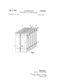
FIGURE 1 is a front elevational view of the electrode of this invention;
FIGURE 2 is a cross-sectional view taken on the line 22 of FIGURE 1;
FIGURE 3 is a partial view of an enlarged detail of the foraminated member; and
FIGURE 4 is a perspective view of an assembly of electrodes.
As shown in the drawings, the electrode 1 is composed of a plurality of foraminated members, such as metal or wire screens 1a. The longitudinal side edges of each screen are bent at a right angle to form side walls 1b and then rebent to form edge flanges 1c. The load-bearing or supporting framework is composed of one or more longitudinally extending tubes 2 to which are attached transversely extending beams 3. These beams can be in the form of flat metal strips, angle irons or tubes.
The electrode is assembled by positioning the supporting framework between a pair of foraminated members 1a with the flanges 1c in contact with the beams 3. The flanges of adjacent electrodes are fastened to beams 3 by being clamped between attachment plates 4 by means of a bolt 4a. The free side edges of the electrode members 1a are likewise clamped against the beam 3 by means of attachment plates in the form of C-shaped clamps 5 and bolts 51:. The edges of flanges 1c are separated from the bolts 4a and 5a, respectively, by a space 6 which serves as an expansion chamber for the thermal expansion of the members 1a and flanges 10. In order to permit this expansion, the bolts 4a and 5a are tightened enough to hold the flange 1c firmly against the beams 3 but loose enough to permit the thermal movement of the flanges. As shown in FIGURE 1, the attachment plates 4 and 5 are positioned at spaced points on the longitudinal edges of flanges 10 where the crossbeams 3 exist.
As shown in FIGURE 4, the supporting framework extends outwardly beyond at least one end of the electrode and is connected to a transverse tube 7 for purposes of support and/or the electrical bus bar for high volt-age. Rods 8 extending between the supporting frameworks for adjacent electrodes are attached to the frameworks for the purpose of keeping the electrodes spaced from each other as accurately as possible.
Having now described the means by which the objects of the invention are obtained, I claim:
1. An electrode for a sparkless condenser field electrostatic gas filter comprising a pair of spaced metal foraminated members lying in substantially parallel vertical planes, inwardly turned vertically extending side walls on each member at each vertically extending end thereof, vertically extending edge flanges bent outwardly of said vertically extending side walls and extending parallel to said members, a metal framework positioned between said members, and attachment plate means fastening each of said flanges to said framework at vertically spaced apart points on said members, said members forming a substantially rectangular box, and adjusting means adjusting said attachment plate means to a position permitting said flanges to slide on said framework during thermal expansion of said members without warping of the electrode while maintaining frictional engagement between said framework and said flanges thereby maintaining said members in a position forming said substantially rectangular box.
2. An electrode as in claim 1, said framework comprising at least one tube and transversely extending beams joined to said tube said beams extending to said spaced apart points.
3. An electrode as in claim 2, said adjusting means including bolts mounted in said attachment plate means for clamping said flanges, to said framework and a flange expansion space between said bolts and said flanges.
4. An electrode as in claim 3, said bolts being tightened enough to hold said flanges in frictional engagement with said beams but loose enough to permit thermal expansion movement of said flanges.
11/1950 Chamberlin 55-156 X 11/1951 Mack 55-156 X 2/1954 Wintermute 55108 X 12/1957 Armstrong et al 55130 12/1958 'Phyl 55148 8/1961 Phyl 55-156 X FOREIGN PATENTS 1/ 1954 France. 2/ 1939 Great Britain.
HARRY B. THORNTON, Primary Examiner.
D. E. TALBERT, Assistant Examiner.
Claims (1)
1. AN ELECTRODE FOR AS SPARKLESS CONDENSER FIELD ELECTROSTATIC GAS FILTER COMPRISING A PAIR OF SPACED METAL FORAMINATED MEMBERS LYING IN SUBSTANTIALLY PARALLEL VERTICAL PLANES, INWARDLY TURNED VERTICALLY EXTENDING SIDE WALLS ON EACH MEMBER AT EACH VERTICALLY EXTENDING END THEREOF, VERTICALLY EXTENDING EDGE FLANGES BENT OUTWARDLY OF SAID VERTICALLY EXTENDING SIDE WALLS AND EXTENDING PARALLEL TO SAID MEMBERS, A METAL FRAMEWORK POSITIONED BETWEEN SAID MEMBERS, AND ATTACHMENT PLATE MEANS FASTENING EACH OF SAID FLANGES TO SAID FRAMEWORK AT VERTICALLY SPACED APART POINTS ON SAID MEMBERS, SAID MEMBERS FORMING A SUBSTANTIALLY RECTANGULAR BOX, AND ADJUSTING MEANS ADJUSTING SAID ATTACHMENT PLATE MEANS TO A POSITION PERMITTING SAID FLANGES TO SLIDE ON SAID FRAMEWORK DURING THERMAL EXPANSION OF SAID MEMBERS WITHOUT WARPING OF THE ELECTRODE WHILE MAINTAINING FRICTIONAL ENGAGEMENT BETWEEN SAID FRAMEWORK AND SAID FLANGES THEREBY MAINTAINING SAID MEMBERS IN A POSITION FORMING SAID SUBSTANTIALLY RECTANGULAR BOX.
Applications Claiming Priority (1)
| Application Number | Priority Date | Filing Date | Title |
|---|---|---|---|
| DEM0046877 | 1963-12-18 |
Publications (1)
| Publication Number | Publication Date |
|---|---|
| US3328940A true US3328940A (en) | 1967-07-04 |
Family
ID=7305734
Family Applications (1)
| Application Number | Title | Priority Date | Filing Date |
|---|---|---|---|
| US414665A Expired - Lifetime US3328940A (en) | 1963-12-18 | 1964-11-30 | Electrostatic gas filter electrode |
Country Status (3)
| Country | Link |
|---|---|
| US (1) | US3328940A (en) |
| AT (1) | AT263157B (en) |
| GB (1) | GB1066290A (en) |
Cited By (4)
| Publication number | Priority date | Publication date | Assignee | Title |
|---|---|---|---|---|
| US3660968A (en) * | 1968-11-19 | 1972-05-09 | Lodge Cottrell Ltd | Electro-precipitators |
| US3788041A (en) * | 1972-09-13 | 1974-01-29 | Gaylord Ind | Electrostatic precipitator for high temperature operation |
| US3803809A (en) * | 1972-07-13 | 1974-04-16 | Metallgesellschaft Ag | Electrostatic precipitator |
| US5163983A (en) * | 1990-07-31 | 1992-11-17 | Samsung Electronics Co., Ltd. | Electronic air cleaner |
Citations (10)
| Publication number | Priority date | Publication date | Assignee | Title |
|---|---|---|---|---|
| US1767338A (en) * | 1927-05-27 | 1930-06-24 | Int Precipitation Co | Electrical precipitating apparatus |
| US1943070A (en) * | 1930-12-23 | 1934-01-09 | Int Precipitation Co | Electrical precipitation apparatus |
| GB500221A (en) * | 1936-08-06 | 1939-02-06 | Max Lehnen | Depositing electrode for electrical gas purification |
| US2529594A (en) * | 1947-12-22 | 1950-11-14 | Research Corp | Collecting electrode structure for electrical precipitators |
| US2575181A (en) * | 1948-07-14 | 1951-11-13 | Wheeling Steel Corp | Precipitator collecting electrode |
| US2668600A (en) * | 1953-04-06 | 1954-02-09 | Research Corp | Electrode structure |
| FR1066141A (en) * | 1951-08-16 | 1954-06-02 | Metallgesellschaft Ag | precipitation electrode for electrostatic precipitators |
| US2815824A (en) * | 1955-05-12 | 1957-12-10 | Research Corp | Electrostatic precipitator |
| US2866517A (en) * | 1956-11-26 | 1958-12-30 | Cottrell Res Inc | Discharge electrode mounting device |
| US2996144A (en) * | 1959-09-09 | 1961-08-15 | Cottrell Res Inc | Collecting electrode |
-
1964
- 1964-11-30 US US414665A patent/US3328940A/en not_active Expired - Lifetime
- 1964-12-02 AT AT1019164A patent/AT263157B/en active
- 1964-12-02 GB GB49046/64A patent/GB1066290A/en not_active Expired
Patent Citations (10)
| Publication number | Priority date | Publication date | Assignee | Title |
|---|---|---|---|---|
| US1767338A (en) * | 1927-05-27 | 1930-06-24 | Int Precipitation Co | Electrical precipitating apparatus |
| US1943070A (en) * | 1930-12-23 | 1934-01-09 | Int Precipitation Co | Electrical precipitation apparatus |
| GB500221A (en) * | 1936-08-06 | 1939-02-06 | Max Lehnen | Depositing electrode for electrical gas purification |
| US2529594A (en) * | 1947-12-22 | 1950-11-14 | Research Corp | Collecting electrode structure for electrical precipitators |
| US2575181A (en) * | 1948-07-14 | 1951-11-13 | Wheeling Steel Corp | Precipitator collecting electrode |
| FR1066141A (en) * | 1951-08-16 | 1954-06-02 | Metallgesellschaft Ag | precipitation electrode for electrostatic precipitators |
| US2668600A (en) * | 1953-04-06 | 1954-02-09 | Research Corp | Electrode structure |
| US2815824A (en) * | 1955-05-12 | 1957-12-10 | Research Corp | Electrostatic precipitator |
| US2866517A (en) * | 1956-11-26 | 1958-12-30 | Cottrell Res Inc | Discharge electrode mounting device |
| US2996144A (en) * | 1959-09-09 | 1961-08-15 | Cottrell Res Inc | Collecting electrode |
Cited By (4)
| Publication number | Priority date | Publication date | Assignee | Title |
|---|---|---|---|---|
| US3660968A (en) * | 1968-11-19 | 1972-05-09 | Lodge Cottrell Ltd | Electro-precipitators |
| US3803809A (en) * | 1972-07-13 | 1974-04-16 | Metallgesellschaft Ag | Electrostatic precipitator |
| US3788041A (en) * | 1972-09-13 | 1974-01-29 | Gaylord Ind | Electrostatic precipitator for high temperature operation |
| US5163983A (en) * | 1990-07-31 | 1992-11-17 | Samsung Electronics Co., Ltd. | Electronic air cleaner |
Also Published As
| Publication number | Publication date |
|---|---|
| GB1066290A (en) | 1967-04-26 |
| AT263157B (en) | 1968-07-10 |
Similar Documents
| Publication | Publication Date | Title |
|---|---|---|
| US3831351A (en) | Electrostatic precipitator | |
| US4259093A (en) | Electrostatic precipitator for air cleaning | |
| US3282029A (en) | Emitting electrode construction for electrostatic separators | |
| US3328940A (en) | Electrostatic gas filter electrode | |
| RU2552566C2 (en) | Electric screening device for structures near high-voltage parts of electrostatic precipitators | |
| US3155474A (en) | Dust separator | |
| US4521229A (en) | Tubular discharge electrode for electrostatic precipitator | |
| JPS6033556B2 (en) | sieving machine | |
| GB1559629A (en) | Electrostatic precipitator | |
| US2826262A (en) | Collecting electrode | |
| US3803809A (en) | Electrostatic precipitator | |
| US4478614A (en) | Electrostatic precipitator construction having spacers | |
| KR19990017814A (en) | Clean Room Filter | |
| US3125426A (en) | Collecting electrodes and electrode system | |
| US2852093A (en) | Discharge electrode | |
| US3793804A (en) | Collector electrode for electrostatic precipitator | |
| US2380992A (en) | Electrical dust-precipitator system and interchangeable parts therefor | |
| US3158453A (en) | Emission electrode system | |
| DE2346196C3 (en) | Electrostatic precipitator | |
| US4273565A (en) | Cyclone support | |
| US3972701A (en) | Electrostatic precipitator having electrode stabilizer means | |
| EP0071742B2 (en) | Combustion chamber for a combustion apparatus | |
| GB1099342A (en) | Improvements in or relating to electro-precipitators | |
| US3576096A (en) | Filter frame latching assembly | |
| US1846169A (en) | Electrical precipitator |