US3313402A - Silhouette safety control for paint spray conveyor - Google Patents
Silhouette safety control for paint spray conveyor Download PDFInfo
- Publication number
- US3313402A US3313402A US363495A US36349564A US3313402A US 3313402 A US3313402 A US 3313402A US 363495 A US363495 A US 363495A US 36349564 A US36349564 A US 36349564A US 3313402 A US3313402 A US 3313402A
- Authority
- US
- United States
- Prior art keywords
- conveyor
- article
- spray painting
- safety control
- orientation
- Prior art date
- Legal status (The legal status is an assumption and is not a legal conclusion. Google has not performed a legal analysis and makes no representation as to the accuracy of the status listed.)
- Expired - Lifetime
Links
Images
Classifications
-
- B—PERFORMING OPERATIONS; TRANSPORTING
- B05—SPRAYING OR ATOMISING IN GENERAL; APPLYING FLUENT MATERIALS TO SURFACES, IN GENERAL
- B05B—SPRAYING APPARATUS; ATOMISING APPARATUS; NOZZLES
- B05B13/00—Machines or plants for applying liquids or other fluent materials to surfaces of objects or other work by spraying, not covered by groups B05B1/00 - B05B11/00
- B05B13/02—Means for supporting work; Arrangement or mounting of spray heads; Adaptation or arrangement of means for feeding work
- B05B13/0221—Means for supporting work; Arrangement or mounting of spray heads; Adaptation or arrangement of means for feeding work characterised by the means for moving or conveying the objects or other work, e.g. conveyor belts
- B05B13/0264—Overhead conveying means, i.e. the object or other work being suspended from the conveying means; Details thereof, e.g. hanging hooks
-
- B—PERFORMING OPERATIONS; TRANSPORTING
- B05—SPRAYING OR ATOMISING IN GENERAL; APPLYING FLUENT MATERIALS TO SURFACES, IN GENERAL
- B05B—SPRAYING APPARATUS; ATOMISING APPARATUS; NOZZLES
- B05B12/00—Arrangements for controlling delivery; Arrangements for controlling the spray area
- B05B12/08—Arrangements for controlling delivery; Arrangements for controlling the spray area responsive to condition of liquid or other fluent material to be discharged, of ambient medium or of target ; responsive to condition of spray devices or of supply means, e.g. pipes, pumps or their drive means
- B05B12/12—Arrangements for controlling delivery; Arrangements for controlling the spray area responsive to condition of liquid or other fluent material to be discharged, of ambient medium or of target ; responsive to condition of spray devices or of supply means, e.g. pipes, pumps or their drive means responsive to conditions of ambient medium or target, e.g. humidity, temperature position or movement of the target relative to the spray apparatus
- B05B12/122—Arrangements for controlling delivery; Arrangements for controlling the spray area responsive to condition of liquid or other fluent material to be discharged, of ambient medium or of target ; responsive to condition of spray devices or of supply means, e.g. pipes, pumps or their drive means responsive to conditions of ambient medium or target, e.g. humidity, temperature position or movement of the target relative to the spray apparatus responsive to presence or shape of target
Definitions
- the present invention relates to spray painting systems, and more particularly, to :a safety control or interlock for a conveyorized automated spray painting system.
- the article In the spray painting or spray treating of an article on an automated basis, the article is typically conveyed past a spray source such as a nozzle or an array of nozzles where it is subjected to a spray treatment. It is often of prime, if not critical, importance that the article be in the proper orientation in relation to the spray source, to insure that it is adequately and properly treated by the spray material. An improper orientation of the article may result in an imperfection in the sprayed article, necessitating its scrapping or re-treating and thus subtantialy increasing production costs.
- a spray source such as a nozzle or an array of nozzles
- a silhouette of the desired orientation of the article to be sprayed is formed by a plurality of electric probes interposed in the path of the conveyed article.
- the probes are associated with a safety control relay in the energizing circuitry of the conveyor and are adapted to stop the conveyor through the opening of the safety relay when any one of the probes is contacted, in any degree, by the article, indicating that the article is misoriented.
- a properly oriented article will pass through the silhouette formed by the probes without any contact and without causing the disruption of the conveyor operation.
- an overhead conveyor comprising an I rail 11 with a movable trolley 12 supported thereon, travels in a predetermined path in an automated painting process through an orientation control station A and a spray painting station B.
- the trolley 12 includes wheels 13 and an article hook 1 from which a conductive or partially conductive article 15 may be suspended.
- the aforementioned conveyor elements are electrical conductors in order that electrical continuity or conductivity between the article 15 and the rail 11 may be established and maintained.
- the spray station B is provided with sources, such as nozzles 52 (shown greatly enlarged), arranged to apply a coating to the article when it is in a predetermined, desired orientation 16 (shown in phantom) therewith.
- sources such as nozzles 52 (shown greatly enlarged), arranged to apply a coating to the article when it is in a predetermined, desired orientation 16 (shown in phantom) therewith.
- the orientation control station A is estabiished by one or more, usualy a series, of probes 17 arranged so that their tips 18 generally outline the dedfildfifiz Patented Apr. 1.1, 1967 sired, predetermined orientation 16.
- the probes are advantageously fabricated from short lengths of piano wire, for example, and are sup-ported in cantilever fashion by opposed walls 19, 2d of a suitable dielectric material.
- the relationship of the stations A and B is, of course, such that the probe elements are maintained free from contamination by sprayed paint.
- the safety interlock of the present invention acts to de-energize the conveyor motor 25 and thus halts the conveyor when an article is detected to be improperly oriented by the probes 17.
- Typical control circuitry for the interlock system generally includes conveyor motor energizing circuitry (starting and stopping) and a safety interlock cricuit associated therewith to de-energize the mortor and/ or to sound an alarm, if desired, when a misoriented article contacts one of the probes 17.
- the energizing circuitry includes a primary power source S, which is connected by conductors 23, 24 to the conveyor motor 25.
- the conductor 23 include-s a pair of relay contacts 26, which are normally open but are closable upon actuation of a two-pole motor operating relay 29.
- the motor starting circuitry includes a normally open starting switch 30, advantageously a pushbutton type switch.
- One side of the start ng switch is connected through a conductor 33 to the conductor 23 at one side of the source S, and the other side is connected through a conductor 34 to the energizing coil of the operating relay 29, the other side of the coil being connected to the condoctor 24 at the other side of the source.
- the motor stopping circuitry includes a conductor 36 connected across the starting switch, between the conductors 33, 34.
- the conductor 26 includes three pairs of contacts 37, 39, 41; a pair of normally open safety switch contacts 37 which is held closed in normal operation by energization of a safety control relay 43; a pair of normally closed, stop button contacts 39; and a pair of contacts 41, holding contacts which are normally open but are closable upon energization of the operating relay 29.
- the safety interlock circuitry includes the aforementioned safety control relay 43, whose energizing coil is connected across the output terminals of an amplifier 48, whose sensitivity is such that it can be adjusted even through relatively highly resistive materials.
- the input to the amplifier is in the nature of a safety control pulse or signal which is created by the contacting, no matter how slight, of a misoriented conductive or partially conductive article by one of the probes 17.
- the article itself may be electrically connected to ground through the hook 14, the trolley 12, the rail 11, and a ground conductor 59, as shown in the drawing, although in some instances it need not be grounded if it has a large enough mass effect.
- the probes 17 are connected to one of the amplifier input terminals by a conductor 49.
- the other amplifier input terminal is connected to ground through a power source S by a conductor 51.
- Operation of the new and improved system is initiated by momentary depression of the start button 30, which will energize the operating relay 29, closing the contacts and energizing the conveyor drive motor 25.
- the relay 29 remains energized through a holding circuit, including its now closed contacts 41.
- the coil of the operating relay will remain energized, maintaining the operation of the conveyor mot-or, until the current thereto is interrupted by the manual depression of the stop button 39 or by the opening of the contacts 37 through energization of the safety control relay 43.
- De-energization of the operating relay 29 by either of these alternatives will open the motor energizing circuit, as will be understood, and will leave the motor circuit open until the relay 29 is once 3 again energized through the depression of the starting button 30.
- the safety control pulse necessary to energize the control relay 43 is created by the closing of an orientation switch (indicated generally at 58), the contacts of which are normally open and which include, as a specific aspect of the invention, the wire probes 17 and the conductive article 15, itself. If the article is not hanging properly as it passes through the control station A, one of the probes 17 will be contacted, momentarily closing an orientation switch and immediately closing down the system. Since the articles contemplated by the invention may be of light weight and since they are freely suspended, switches of the typical positive action or position displacement types would not be suitable for use as or in lieu of an orientation switch, because a typical misoriented part would possess insufiicient inertia to actuate such a conventional switch reliably. Therefore, the importance of the use of the electroconductive article 15, itself, the amplifier 48, and the conductive conveyor elements 11-14 as integral elements of the electrical interlock system should be well understood.
- the simplified and unique system of the present invention provides a high degree of safety control for a spray paint system in which proper orientation of the article being painted is important to the ultimate success of the process.
- utilization of simple wire probes in combination with an amplifier and the conductive conveyor elements to create an effective safety control pulse provides a very inexpensive, yet extremely reliable and efiicient, safety control for the system.
- the wire probes 17 may be one or more in number and adjustably mounted for inward and outward movement.
- parts of various configurations may be accommodated by the control system.
- Safety control for a spray painting system compris- (a) conveyor means adapted to transport a suspended electroconductive article having a predetermined, desired outline and orientation in a predetermined P (b) a spray painting station located at a point in said path,
- control station having an array of wire-like probe elements generally defining said predetermined outline
- interlock relay means associated with said amplifier and said first circuit means and adapted to deenergize said conveyor means upon completion of said second circuit means.
- Safety control for a spray painting system compris- (a) conveyor means adapted to transport a suspended electroconductive article having a predetermined, desired outline and orientation in a predetermined path,
- control station having an array of wire-like probe elements generally defining said predetermined outline
- interlock relay means associated with said amplifier and said first circuit means and adapted to change the condition of said control switch upon completion of said second circuit means.
- Safety control for a spray painting system compris- (a) conveyor means adapted to transport a suspended electroconductive article having a predetermined, desired outline and orientation in a predetermined path,
- control station having an array of wire-like probe elements generally defining said predetermined outline
- said interlock relay means being adapted to change the condition of said control switch upon completion of said second circuit means.
Landscapes
- Spray Control Apparatus (AREA)
Description
April 11, 1967 R. F. WIGGINS SILHOUETTE SAFETY CONTROL FOR PAINT SPRAY CONVEYOR Filed April 29, 1964 rill I llll'll lnlll'llllvllllllllllalllll.
. pill/I47 EEEE a E rw ATTORNEYS United States Patent 3,313,402 SILHOUETTE SAFETY CONTRGL FOR PAINT SPRAY CONVEYOR Richard F. Wiggins, Fairfield, Conn, assignor to The Gyrornat Corporation, Fairfield, Comp, a corporation of Connecticut Filed Apr. 29, 1964, Ser. No. 363,495 3 Claims. (Cl. 198232) The present invention relates to spray painting systems, and more particularly, to :a safety control or interlock for a conveyorized automated spray painting system.
In the spray painting or spray treating of an article on an automated basis, the article is typically conveyed past a spray source such as a nozzle or an array of nozzles where it is subjected to a spray treatment. It is often of prime, if not critical, importance that the article be in the proper orientation in relation to the spray source, to insure that it is adequately and properly treated by the spray material. An improper orientation of the article may result in an imperfection in the sprayed article, necessitating its scrapping or re-treating and thus subtantialy increasing production costs.
Accordingly, it is an object of the present invention to provide a highly simplified, yet wholly effective safety control system for a conveyor which all automatically shut down the conveyor or provide a warning when an article to be spray painted is not properly oriented at it approaches a spray treatment station. More specifically, it is an object to provide an interlock for a conveyor carrying suspended conductive or partially conductive articles through an electrostatic or other spray painting station.
In accordance with an important aspect of the invention, a silhouette of the desired orientation of the article to be sprayed is formed by a plurality of electric probes interposed in the path of the conveyed article. The probes are associated with a safety control relay in the energizing circuitry of the conveyor and are adapted to stop the conveyor through the opening of the safety relay when any one of the probes is contacted, in any degree, by the article, indicating that the article is misoriented. A properly oriented article will pass through the silhouette formed by the probes without any contact and without causing the disruption of the conveyor operation.
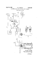
For a more complete understandin g of the invention and its attendant advantages, reference should be made to the following detailed description taken in conjunction with the accompanying drawing showin a schematic representation of the new and improved safety interlock for a conveyorized spray painting system.
in accordance with the invention, an overhead conveyor comprising an I rail 11 with a movable trolley 12 supported thereon, travels in a predetermined path in an automated painting process through an orientation control station A and a spray painting station B. As shown, the trolley 12 includes wheels 13 and an article hook 1 from which a conductive or partially conductive article 15 may be suspended. As a specific aspect of the invention, the aforementioned conveyor elements are electrical conductors in order that electrical continuity or conductivity between the article 15 and the rail 11 may be established and maintained.
The spray station B is provided with sources, such as nozzles 52 (shown greatly enlarged), arranged to apply a coating to the article when it is in a predetermined, desired orientation 16 (shown in phantom) therewith.
In accordance with an important aspect of the invention, at a point in the conveyor path in advance of the spray station B, the orientation control station A is estabiished by one or more, usualy a series, of probes 17 arranged so that their tips 18 generally outline the dedfildfifiz Patented Apr. 1.1, 1967 sired, predetermined orientation 16. The probes are advantageously fabricated from short lengths of piano wire, for example, and are sup-ported in cantilever fashion by opposed walls 19, 2d of a suitable dielectric material. The relationship of the stations A and B is, of course, such that the probe elements are maintained free from contamination by sprayed paint.
The safety interlock of the present invention acts to de-energize the conveyor motor 25 and thus halts the conveyor when an article is detected to be improperly oriented by the probes 17. Typical control circuitry for the interlock system generally includes conveyor motor energizing circuitry (starting and stopping) and a safety interlock cricuit associated therewith to de-energize the mortor and/ or to sound an alarm, if desired, when a misoriented article contacts one of the probes 17.
More specifically, the energizing circuitry includes a primary power source S, which is connected by conductors 23, 24 to the conveyor motor 25. The conductor 23 include-s a pair of relay contacts 26, which are normally open but are closable upon actuation of a two-pole motor operating relay 29.
The motor starting circuitry includes a normally open starting switch 30, advantageously a pushbutton type switch. One side of the start ng switch is connected through a conductor 33 to the conductor 23 at one side of the source S, and the other side is connected through a conductor 34 to the energizing coil of the operating relay 29, the other side of the coil being connected to the condoctor 24 at the other side of the source.
The motor stopping circuitry includes a conductor 36 connected across the starting switch, between the conductors 33, 34. The conductor 26 includes three pairs of contacts 37, 39, 41; a pair of normally open safety switch contacts 37 which is held closed in normal operation by energization of a safety control relay 43; a pair of normally closed, stop button contacts 39; and a pair of contacts 41, holding contacts which are normally open but are closable upon energization of the operating relay 29.
The safety interlock circuitry includes the aforementioned safety control relay 43, whose energizing coil is connected across the output terminals of an amplifier 48, whose sensitivity is such that it can be adjusted even through relatively highly resistive materials. In accordance with the invention, the input to the amplifier is in the nature of a safety control pulse or signal which is created by the contacting, no matter how slight, of a misoriented conductive or partially conductive article by one of the probes 17. The article itself may be electrically connected to ground through the hook 14, the trolley 12, the rail 11, and a ground conductor 59, as shown in the drawing, although in some instances it need not be grounded if it has a large enough mass effect. As shown, the probes 17 are connected to one of the amplifier input terminals by a conductor 49. The other amplifier input terminal is connected to ground through a power source S by a conductor 51.
Operation of the new and improved system is initiated by momentary depression of the start button 30, which will energize the operating relay 29, closing the contacts and energizing the conveyor drive motor 25. After momentary closure of the start switch 30, the relay 29 remains energized through a holding circuit, including its now closed contacts 41. The coil of the operating relay will remain energized, maintaining the operation of the conveyor mot-or, until the current thereto is interrupted by the manual depression of the stop button 39 or by the opening of the contacts 37 through energization of the safety control relay 43. De-energization of the operating relay 29 by either of these alternatives will open the motor energizing circuit, as will be understood, and will leave the motor circuit open until the relay 29 is once 3 again energized through the depression of the starting button 30.
The safety control pulse necessary to energize the control relay 43 is created by the closing of an orientation switch (indicated generally at 58), the contacts of which are normally open and which include, as a specific aspect of the invention, the wire probes 17 and the conductive article 15, itself. If the article is not hanging properly as it passes through the control station A, one of the probes 17 will be contacted, momentarily closing an orientation switch and immediately closing down the system. Since the articles contemplated by the invention may be of light weight and since they are freely suspended, switches of the typical positive action or position displacement types would not be suitable for use as or in lieu of an orientation switch, because a typical misoriented part would possess insufiicient inertia to actuate such a conventional switch reliably. Therefore, the importance of the use of the electroconductive article 15, itself, the amplifier 48, and the conductive conveyor elements 11-14 as integral elements of the electrical interlock system should be well understood.
It will be appreciated that the simplified and unique system of the present invention, provides a high degree of safety control for a spray paint system in which proper orientation of the article being painted is important to the ultimate success of the process. Moreover, utilization of simple wire probes in combination with an amplifier and the conductive conveyor elements to create an effective safety control pulse provides a very inexpensive, yet extremely reliable and efiicient, safety control for the system.
In a typical system, the wire probes 17 may be one or more in number and adjustably mounted for inward and outward movement. Thus, parts of various configurations may be accommodated by the control system.
Although the present invention has been described with reference to a specific preferred embodiment, it should be understood that the description has been made by way of example, and that certain changes in details of construction and arrangement of the elements may be made without departing from the scope of the invention as hereinafter claimed.
1 claim:
1. Safety control for a spray painting system, compris- (a) conveyor means adapted to transport a suspended electroconductive article having a predetermined, desired outline and orientation in a predetermined P (b) a spray painting station located at a point in said path,
(c) an orientation control station located in said path in advance of said spray painting station,
(d) said control station having an array of wire-like probe elements generally defining said predetermined outline,
(e) first electrical circuit means energizing said conveyor means,
(f) amplification means in association with said conveyor means and said probe elements, and
(g) second electrical circuit means normally open but being closable upon contact of an improperly oriented article with one of said probes, and
(h) interlock relay means associated with said amplifier and said first circuit means and adapted to deenergize said conveyor means upon completion of said second circuit means.
2. Safety control for a spray painting system, compris- (a) conveyor means adapted to transport a suspended electroconductive article having a predetermined, desired outline and orientation in a predetermined path,
(b) a spray painting station located at a point in said path,
(c) an orientation control station located in said path in advance of said spray painting station,
(d) said control station having an array of wire-like probe elements generally defining said predetermined outline;
(e) first electrical circuit means including a control switch,
(f) amplification means in association with said first electrical circuit means and said probe elements, and
(g) second electrical circuit means normally open but being closable upon contact of an improperly oriented article with one of said probes, and
(h) interlock relay means associated with said amplifier and said first circuit means and adapted to change the condition of said control switch upon completion of said second circuit means.
3. Safety control for a spray painting system, compris- (a) conveyor means adapted to transport a suspended electroconductive article having a predetermined, desired outline and orientation in a predetermined path,
(b) a spray painting station located at a point in said path,
(c) an orientation control station located in said path in advance of said spray painting station,
((1) said control station having an array of wire-like probe elements generally defining said predetermined outline,
(e) first electrical circuit means including a control switch,
(f) interlock relay means in association with said first electrical circuit means and said probe elements, and
(g) second electrical circuit means normally open but being closable upon contact of an improperly oriented article with one of said probes, and
(h) said interlock relay means being adapted to change the condition of said control switch upon completion of said second circuit means.
References Cited by the Examiner UNITED STATES PATENTS 1,350,774 8/1920 Braley 198232 1,368,583 2/1921 Thompson .198232 1,803,689 5/1931 Bernadt 198-37 3,129,807 4/1964 Richter 198232 FOREIGN PATENTS 550,355 10/1956 Italy.
EVON C. BLUNK, Primary Examiner.
EDWARD A. SROKA, Examiner.
Claims (1)
1. SAFETY CONTROL FOR A SPRAY PAINTING SYSTEM, COMPRISING (A) CONVEYOR MEANS ADAPTED TO TRANSPORT A SUSPENDED ELECTROCONDUCTIVE ARTICLE HAVING A PREDETERMINED, DESIRED OUTLINE AND ORIENTATION IN A PREDETERMINED PATH, (B) A SPRAY PAINTING STATION LOCATED AT A POINT IN SAID PATH, (C) AN ORIENTATION CONTROL STATION LOCATED IN SAID PATH IN ADVANCE OF SAID SPRAY PAINTING STATION, (D) SAID CONTROL STATION HAVING AN ARRAY OF WIRE-LIKE PROBE ELEMENTS GENERALLY DEFINING SAID PREDETERMINED OUTLINE, (E) FIRST ELECTRICAL CIRCUIT MEANS ENERGIZING SAID CONVEYOR MEANS, (F) AMPLIFICATION MEANS IN ASSOCIATION WITH SAID CONVEYOR MEANS AND SAID PROBE ELEMENTS, AND (G) SECOND ELECTRICAL CIRCUIT MEANS NORMALLY OPEN BUT BEING CLOSABLE UPON CONTACT OF AN IMPROPERLY ORIENTED ARTICLE WITH ONE OF SAID PROBES, AND (H) INTERLOCK RELAY MEANS ASSOCIATED WITH SAID AMPLIFIER AND SAID FIRST CIRCUIT MEANS AND ADAPTED TO DEENERGIZE SAID CONVEYOR MEANS UPON COMPLETION OF SAID SECOND CIRCUIT MEANS.
Priority Applications (1)
| Application Number | Priority Date | Filing Date | Title |
|---|---|---|---|
| US363495A US3313402A (en) | 1964-04-29 | 1964-04-29 | Silhouette safety control for paint spray conveyor |
Applications Claiming Priority (1)
| Application Number | Priority Date | Filing Date | Title |
|---|---|---|---|
| US363495A US3313402A (en) | 1964-04-29 | 1964-04-29 | Silhouette safety control for paint spray conveyor |
Publications (1)
| Publication Number | Publication Date |
|---|---|
| US3313402A true US3313402A (en) | 1967-04-11 |
Family
ID=23430466
Family Applications (1)
| Application Number | Title | Priority Date | Filing Date |
|---|---|---|---|
| US363495A Expired - Lifetime US3313402A (en) | 1964-04-29 | 1964-04-29 | Silhouette safety control for paint spray conveyor |
Country Status (1)
| Country | Link |
|---|---|
| US (1) | US3313402A (en) |
Citations (4)
| Publication number | Priority date | Publication date | Assignee | Title |
|---|---|---|---|---|
| US1350774A (en) * | 1920-08-24 | Chain conveyer | ||
| US1368583A (en) * | 1919-07-10 | 1921-02-15 | Thomas F Ryan | Machine-tool |
| US1803689A (en) * | 1929-12-27 | 1931-05-05 | Walter H Bernadt | Conveyer control |
| US3129807A (en) * | 1960-12-29 | 1964-04-21 | Svit Np | Safety device for a manufacturing conveyor |
-
1964
- 1964-04-29 US US363495A patent/US3313402A/en not_active Expired - Lifetime
Patent Citations (4)
| Publication number | Priority date | Publication date | Assignee | Title |
|---|---|---|---|---|
| US1350774A (en) * | 1920-08-24 | Chain conveyer | ||
| US1368583A (en) * | 1919-07-10 | 1921-02-15 | Thomas F Ryan | Machine-tool |
| US1803689A (en) * | 1929-12-27 | 1931-05-05 | Walter H Bernadt | Conveyer control |
| US3129807A (en) * | 1960-12-29 | 1964-04-21 | Svit Np | Safety device for a manufacturing conveyor |
Similar Documents
| Publication | Publication Date | Title |
|---|---|---|
| US1868894A (en) | Conveyer | |
| US2509448A (en) | Apparatus for electrostatically coating articles | |
| US2886164A (en) | Conveyors | |
| US1528227A (en) | Conveyer system | |
| US3313402A (en) | Silhouette safety control for paint spray conveyor | |
| US2421343A (en) | Article coating apparatus | |
| US3482110A (en) | Device for automatically rendering apparatus inoperative when subjected to shock | |
| US2270428A (en) | Can-sorting machine | |
| US2688932A (en) | Conveyer apparatus and control system therefor | |
| US2401115A (en) | Traveling conveyer apparatus | |
| US1697757A (en) | Automatic direction-controlling mechanism | |
| US2084879A (en) | Conveyer block system | |
| US3569642A (en) | Control for sheet feeding apparatus | |
| US2486222A (en) | Conveyer apparatus and control systems therefor | |
| US2879885A (en) | Pole safety device for dry room conveyor | |
| GB954946A (en) | Improvements in or relating to the spraying of sheet-like material | |
| US2966881A (en) | Timing control device | |
| US2544806A (en) | Electrostatic coating apparatus | |
| US2968747A (en) | Sequence counting and locking circuit | |
| GB642903A (en) | Improvements in or relating to apparatus for controlling and/or indicating variations in the thickness of material | |
| US3112395A (en) | Indicating counter device | |
| US3191745A (en) | Conveyors | |
| US1508770A (en) | System of motor control | |
| US2803341A (en) | Metal detecting device | |
| US3596086A (en) | Automatic conveyor block system |