US329902A - Natural-gas-supply system - Google Patents
Natural-gas-supply system Download PDFInfo
- Publication number
- US329902A US329902A US329902DA US329902A US 329902 A US329902 A US 329902A US 329902D A US329902D A US 329902DA US 329902 A US329902 A US 329902A
- Authority
- US
- United States
- Prior art keywords
- gas
- well
- pressure
- wells
- natural
- Prior art date
- Legal status (The legal status is an assumption and is not a legal conclusion. Google has not performed a legal analysis and makes no representation as to the accuracy of the status listed.)
- Expired - Lifetime
Links
Images

Classifications
-
- C—CHEMISTRY; METALLURGY
- C01—INORGANIC CHEMISTRY
- C01B—NON-METALLIC ELEMENTS; COMPOUNDS THEREOF; METALLOIDS OR COMPOUNDS THEREOF NOT COVERED BY SUBCLASS C01C
- C01B3/00—Hydrogen; Gaseous mixtures containing hydrogen; Separation of hydrogen from mixtures containing it; Purification of hydrogen
- C01B3/0005—Reversible uptake of hydrogen by an appropriate medium, i.e. based on physical or chemical sorption phenomena or on reversible chemical reactions, e.g. for hydrogen storage purposes ; Reversible gettering of hydrogen; Reversible uptake of hydrogen by electrodes
-
- Y—GENERAL TAGGING OF NEW TECHNOLOGICAL DEVELOPMENTS; GENERAL TAGGING OF CROSS-SECTIONAL TECHNOLOGIES SPANNING OVER SEVERAL SECTIONS OF THE IPC; TECHNICAL SUBJECTS COVERED BY FORMER USPC CROSS-REFERENCE ART COLLECTIONS [XRACs] AND DIGESTS
- Y02—TECHNOLOGIES OR APPLICATIONS FOR MITIGATION OR ADAPTATION AGAINST CLIMATE CHANGE
- Y02E—REDUCTION OF GREENHOUSE GAS [GHG] EMISSIONS, RELATED TO ENERGY GENERATION, TRANSMISSION OR DISTRIBUTION
- Y02E60/00—Enabling technologies; Technologies with a potential or indirect contribution to GHG emissions mitigation
- Y02E60/30—Hydrogen technology
- Y02E60/32—Hydrogen storage
-
- Y—GENERAL TAGGING OF NEW TECHNOLOGICAL DEVELOPMENTS; GENERAL TAGGING OF CROSS-SECTIONAL TECHNOLOGIES SPANNING OVER SEVERAL SECTIONS OF THE IPC; TECHNICAL SUBJECTS COVERED BY FORMER USPC CROSS-REFERENCE ART COLLECTIONS [XRACs] AND DIGESTS
- Y10—TECHNICAL SUBJECTS COVERED BY FORMER USPC
- Y10T—TECHNICAL SUBJECTS COVERED BY FORMER US CLASSIFICATION
- Y10T137/00—Fluid handling
- Y10T137/7722—Line condition change responsive valves
- Y10T137/7781—With separate connected fluid reactor surface
- Y10T137/7793—With opening bias [e.g., pressure regulator]
- Y10T137/7809—Reactor surface separated by apertured partition
- Y10T137/7812—Valve stem passes through the aperture
- Y10T137/7818—Valve head in inlet chamber
- Y10T137/7819—Rectilinear valve stem rigid with reactor surface
-
- Y—GENERAL TAGGING OF NEW TECHNOLOGICAL DEVELOPMENTS; GENERAL TAGGING OF CROSS-SECTIONAL TECHNOLOGIES SPANNING OVER SEVERAL SECTIONS OF THE IPC; TECHNICAL SUBJECTS COVERED BY FORMER USPC CROSS-REFERENCE ART COLLECTIONS [XRACs] AND DIGESTS
- Y10—TECHNICAL SUBJECTS COVERED BY FORMER USPC
- Y10T—TECHNICAL SUBJECTS COVERED BY FORMER US CLASSIFICATION
- Y10T137/00—Fluid handling
- Y10T137/7722—Line condition change responsive valves
- Y10T137/7781—With separate connected fluid reactor surface
- Y10T137/7793—With opening bias [e.g., pressure regulator]
- Y10T137/7809—Reactor surface separated by apertured partition
- Y10T137/782—Reactor surface is diaphragm
Definitions
- This invention relates to the means for receiving natural gas from the gas-wells, regulating its ilow from the wells, conveying it to the consumer, and regulating the pressure in the conduits.
- the supplying system of a town or city is commonly connected with a series of wells, and these wells are constantly varying in the volume and force of gas emitted, while the gas in the conduits must be maintained at an even pressure.
- Gas-wells often emit gas at enormous pressure, While the supply-conduits should maintain a pressure of only a few ounces to the square inch. Often a gas- Well will cease owing entirely, and will sometimes become a consumer of gas,sucking it from the mains.
- a pressure-regulating valve which permits only so much gas to enter the conduits as may be desired and retains the rest in the tubing and that part of the well below the packer.
- gas-Wells discharge some oil and sometimes water. Such discharges should not be allowed to enter the conduits, and so we provide a trap to catch the same and prevent them entering the conduits.
- Figure l is a diagram showing a series v0f gas-wells connected with and supplying a single main.
- Fig. 2 is a vertical section of a gas-well.
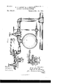
- Fig. 3, is a side elevation of a trap.
- Fig. 4 is an elevation view showing the connection of a well with the main and the relative positions of the regulating-valve and the trap.
- Fig. 5 is a vertical sectional view of regulating-valve.
- A marks the floor of a well-derrick, B the drive-pipe, C the casing, D the tubing, and E the packer. These parts are all the same or substantially the same as is commonly employed in oil-wells.
- tubing and packer have not been used in a gas-well, but the gas has been taken direct from the casing.
- the object in using the tubing and packer is to keep the gas confined in its native rock and not allow it to enter the seams or fissures of the rocks above, and also to enable a perfect control of the whole product of the well, as above. explained.
- a diaphragm, f' On the top of the way d is a diaphragm, f', which closes it.
- the gas has free access to the diaphragm.
- the diaphragm is Weighted by the weight/f4 on the lever f3, which acts on a plunger, f2, working through a cap over the diaphragm.
- the piston acting on the wide surface of the diaphragm, the piston,which is connected to the diaphragm,will be raised and close the ports.
- the adjustment of the weight f4 on the lever f3 will determine the degree of pressure which shall obtain in the way d. rlhe 'conduit D discharges into the trap G.
- This trap is a cylindrical iron tank, which Vwe generally make about three feet in diameter and about ten feet long. It has a waste-pipe, G, for drawing off any oil or water which may be discharged from the well and caught by the trap. From the trap the gas is conveyed by the feeder-pipe H into the main I. A shut-off gate, K, is provided in the feeder H, so as to cut the well off from the main at any time de- Sired.
- a gas-well havn ing a pressure of gas in the well of more than one hundred pounds to the square inch may supply the main with gas at as low a pressure as may be desired.
- the pressure in any well may vary from zero to hundreds of pounds,
- Fig. 1 shows a main in the field connected with'a number of wells, each ofgwhich is pro vided with the devices described above, thus bination,with the mains thereof, of a series of gas-wells connected with said mains, each of which is provided with a packerfor conning the gas within its native rock, a tube for conveying gas from below said packer to the surface of the earth, and a pressure-regulating valve in the conduit leading from the well to the mains for regulating the discharge of gas from the well in ,accordance with the consumption from the mains, substantially as described.
- the com-- bination with the mains thereof, of a series of gas-wells connected with said mains, each of which is provided with a packer for confining the gas within its native rock, a tube for conveying gas from below said packer to the surface of the earth, a pressure-regulating valve for regulating the discharge of gas from the well in accordance with the consumption from the mains, and a trap for receiving any oil or water which may be discharged from the well, substantially as described.
- a natural-gassupply system the combination, substantially as herein set forth, of a gas-well, a packer in said well above the gasproducing rock, a tube leading from said packer to the mouth .of the well, a pressureregulating valve for regulating the discharge from said well in accordance with the consumption from the system, a trap for catching any oil or water that may be discharged from the well, a conduit leading from the top of said trap to the mains of the system, and a waste or drain pipe leading from the bottom of said trap.
Landscapes
- Chemical & Material Sciences (AREA)
- Organic Chemistry (AREA)
- Chemical Kinetics & Catalysis (AREA)
- Engineering & Computer Science (AREA)
- Combustion & Propulsion (AREA)
- Inorganic Chemistry (AREA)
- Pipeline Systems (AREA)
Description
(No Model.) 2 Sheets-Sheet 1.
W. C. HENRY 8u A. SMEDLEY.
NATURAL GAS SUPPLY SYSTEM.
(No Model.) 2 Sheets--Sheet 2.
W. O. HENRY 8v A. SMEDLEY.
NATURAL GAS SUPPLY SYSTEM.
No. 329,902. Patented NOV. 10, 1885.
lll
UNITED STATES PATENT EETCE.
WILLIAM C. HENRY AND ALFRED SMEDLEY, OF BRADFORD, PENNSYLVANIA.
NATURAL-GAS-SUPPLY SYSTEM.
SPECIFICATION forming part of Letters Patent No. 329,902, dated November 10, .1885. Application filed September 11, 1885. Serial No. 176,760. (No model.)
.To all whom it may concern.-
Be it known that we,` WILLIAM C. HENRY and ALFRED SMEDLEY, citizens of the United States, residing at Bradford, in the county of McKean and State of Pennsylvania, have invented certain new and useful Improvements in Natural- Gas-Supply Systems; and we do hereby declare the following to be a full, clear, and exact description of the invention, such as will enable others skilled in the art to which it appertains to make and use the same.
This invention relates to the means for receiving natural gas from the gas-wells, regulating its ilow from the wells, conveying it to the consumer, and regulating the pressure in the conduits.
Gas issues from a gas-well irregularly, and at times with great force, and to convey it in conduits to the consumers it must be so regulated that an even and a much lower pressure than often obtains in the Wells must obtain in the conduits. The supplying system of a town or city is commonly connected with a series of wells, and these wells are constantly varying in the volume and force of gas emitted, while the gas in the conduits must be maintained at an even pressure. Gas-wells often emit gas at enormous pressure, While the supply-conduits should maintain a pressure of only a few ounces to the square inch. Often a gas- Well will cease owing entirely, and will sometimes become a consumer of gas,sucking it from the mains. It will therefore be seen that a system of regulating devices must be employed to obtain the desired results. Heretofore it has been the practice of some to use small gasometers at the wells. This is not very expensive but has not proved satisfactory. It has also been the practice of some to use at each well a valve, which will admit only a given pressure of gas to the conduit and allow the rest of f the product of the well to escape into the open air, thus wasting immense quantities of gas. Gas-wells are drilled the same as oil-wellsthat is to say, they are cased down below all the water-veins and then drilled dry until the gas-producing rock is found. It has been the practice to take the gas from the well through the casing-head. The result of this practice is that where the pressure of gas in the well is great the casing is not strong enough to hold it, and therefore it must be allowed to escape into the open air. While it would be easy to use casing of sufficient strength to stand the pressure, it would be difficult, if not impossible, to keep a tight joint at the bottom of the casing, as the pressure would tend to lift the pipe or casing, and the slightest movement would be fatal, as it would allow the gas to escape into the lateral fissures of the rock and also allow the water held back by the casing to fill the well. So it is impracticable to confine the whole product of a highly-productive well within it and use only so much as is re! quired for supply to the mains, and therefore it is the general practice to allow a free relief escape into the open air. XVe have overcome this difficulty by tubing and packing the gaswells the same as oil-wells are tubed and packed. This connes the gas within its native rock, allows none to enter the well except that part of the well which is in the gas-rock, and the supply of gas is taken from the tubing. By thus proceeding the product of the well is under perfect control and not a particle of gas need be wasted in any manner, and there is no strain whatever put on the casing.
We employ at the mouth of the well on the tubing,or the pipe leading from the tubing, a pressure-regulating valve, which permits only so much gas to enter the conduits as may be desired and retains the rest in the tubing and that part of the well below the packer.
In some localities gas-Wells discharge some oil and sometimes water. Such discharges should not be allowed to enter the conduits, and so we provide a trap to catch the same and prevent them entering the conduits.
The accompanying drawings illustrate our invention as follows: Figure l is a diagram showing a series v0f gas-wells connected with and supplying a single main. Fig. 2 is a vertical section of a gas-well. Fig. 3, is a side elevation of a trap. Fig. 4 is an elevation view showing the connection of a well with the main and the relative positions of the regulating-valve and the trap. Fig. 5 is a vertical sectional view of regulating-valve.
A marks the floor of a well-derrick, B the drive-pipe, C the casing, D the tubing, and E the packer. These parts are all the same or substantially the same as is commonly employed in oil-wells.
Previous to our invention, so far as we are IOO lIo
aware, the tubing and packer have not been used in a gas-well, but the gas has been taken direct from the casing. The object in using the tubing and packer is to keep the gas confined in its native rock and not allow it to enter the seams or fissures of the rocks above, and also to enable a perfect control of the whole product of the well, as above. explained.
At the top of the tubing there is a T-tting and a blow-off pipe, D2, with.gatevalve .I on
- one side and the conduit-pipe D on the other p in the shell of the valve. through the Way d, passes through the port p side. The blow-off or waste pipe is used when it is found necessary for any reason to exhaust the well. The conduit D leads to the trap G, and in it is placed the regulatingvalve F.
VThere are several different types of pressurey' Vand the piston f, and out through the way d.
On the top of the way d is a diaphragm, f', which closes it. The gas has free access to the diaphragm. The diaphragm is Weighted by the weight/f4 on the lever f3, which acts on a plunger, f2, working through a cap over the diaphragm. When the pressure of the gas in the way d is strong enough to lift the weight f4, acting on the wide surface of the diaphragm, the piston,which is connected to the diaphragm,will be raised and close the ports. The adjustment of the weight f4 on the lever f3 will determine the degree of pressure which shall obtain in the way d. rlhe 'conduit D discharges into the trap G. This trap is a cylindrical iron tank, which Vwe generally make about three feet in diameter and about ten feet long. It has a waste-pipe, G, for drawing off any oil or water which may be discharged from the well and caught by the trap. From the trap the gas is conveyed by the feeder-pipe H into the main I. A shut-off gate, K, is provided in the feeder H, so as to cut the well off from the main at any time de- Sired.
By the device just described a gas-well havn ing a pressure of gas in the well of more than one hundred pounds to the square inch may supply the main with gas at as low a pressure as may be desired. The pressure in any well may vary from zero to hundreds of pounds,
but it will not effect the general pressure in the main to which other wells are connected.
Fig. 1 shows a main in the field connected with'a number of wells, each ofgwhich is pro vided with the devices described above, thus bination,with the mains thereof, of a series of gas-wells connected with said mains, each of which is provided with a packerfor conning the gas within its native rock, a tube for conveying gas from below said packer to the surface of the earth, and a pressure-regulating valve in the conduit leading from the well to the mains for regulating the discharge of gas from the well in ,accordance with the consumption from the mains, substantially as described. l Y
2. In a natural gas-supply system, the com-- bination,with the mains thereof, of a series of gas-wells connected with said mains, each of which is provided with a packer for confining the gas within its native rock, a tube for conveying gas from below said packer to the surface of the earth, a pressure-regulating valve for regulating the discharge of gas from the well in accordance with the consumption from the mains, and a trap for receiving any oil or water which may be discharged from the well, substantially as described.
3. In a natural-gassupply system, the combination, substantially as herein set forth, of a gas-well, a packer in said well above the gasproducing rock, a tube leading from said packer to the mouth .of the well, a pressureregulating valve for regulating the discharge from said well in accordance with the consumption from the system, a trap for catching any oil or water that may be discharged from the well, a conduit leading from the top of said trap to the mains of the system, and a waste or drain pipe leading from the bottom of said trap.
4. In a natural-gas-supply system, the combination, with. the mains or conduits thereof, of a gas-well having therein a gas-eduction tube extending to the gas-producing rock, a packer on said tube located above said gasproducing rock and serving to. prevent the escape of gas into the well, and valve on thev eductio'n-tube which regulates the discharge therefrom in accordance with the pressure in the conduits of the system. f
In testimony whereof we affix our signatures in presence of two witnesses. .l
V. C. HENRY. ALFRED SMEDLEY.
Witnesses: y
JNO. K. HALLooK, E. F. SPAULDING.
Publications (1)
| Publication Number | Publication Date |
|---|---|
| US329902A true US329902A (en) | 1885-11-10 |
Family
ID=2399009
Family Applications (1)
| Application Number | Title | Priority Date | Filing Date |
|---|---|---|---|
| US329902D Expired - Lifetime US329902A (en) | Natural-gas-supply system |
Country Status (1)
| Country | Link |
|---|---|
| US (1) | US329902A (en) |
-
0
- US US329902D patent/US329902A/en not_active Expired - Lifetime
Similar Documents
| Publication | Publication Date | Title |
|---|---|---|
| US3858401A (en) | Flotation means for subsea well riser | |
| US3992889A (en) | Flotation means for subsea well riser | |
| US3268017A (en) | Drilling with two fluids | |
| NO329453B1 (en) | Pressure control device and method | |
| BR112014026864B1 (en) | system, and method | |
| US3693732A (en) | Apparatus for controlling pressure in a well | |
| US1455731A (en) | Automatic blow-out preventer | |
| US329902A (en) | Natural-gas-supply system | |
| NO162091B (en) | PROCEDURE AND PLANT FOR THE EXTRACTION OF OIL BY BURNING IN SITU FROM A SEDIMENTARY FORM. | |
| US2642812A (en) | Well flow apparatus | |
| USRE26220E (en) | Method and apparatus for well control | |
| US2034798A (en) | Method of flowing wells | |
| US404397A (en) | Device for ejecting oil from oil-wells | |
| NO311449B1 (en) | Method of controlling the amount of gas injected into a production string and method of reducing instability in a production string located in continuous gas lift boiler | |
| US2643208A (en) | Apparatus for the selective injection of fluids into geological formations | |
| US1057789A (en) | Method of cementing the walls of a hole. | |
| US1153373A (en) | Fluid-elevator. | |
| US703819A (en) | Gas, oil, and water separator. | |
| US2309383A (en) | Deep well pump | |
| US310841A (en) | Means for preventing leakage from gas-conducting mains | |
| AU2015394221A1 (en) | Method and system for controlling gas flow | |
| US51008A (en) | Improvement in oil-ejectors | |
| US422848A (en) | Vent de st | |
| US2245010A (en) | System and apparatus for flowing wells | |
| US406261A (en) | Gas-pressure pump |