US329058A - Peters - Google Patents
Peters Download PDFInfo
- Publication number
- US329058A US329058A US329058DA US329058A US 329058 A US329058 A US 329058A US 329058D A US329058D A US 329058DA US 329058 A US329058 A US 329058A
- Authority
- US
- United States
- Prior art keywords
- gas
- air
- generators
- furnace
- hearth
- Prior art date
- Legal status (The legal status is an assumption and is not a legal conclusion. Google has not performed a legal analysis and makes no representation as to the accuracy of the status listed.)
- Expired - Lifetime
Links
- 239000007789 gas Substances 0.000 description 38
- 238000002485 combustion reaction Methods 0.000 description 15
- 239000000446 fuel Substances 0.000 description 11
- 206010022000 influenza Diseases 0.000 description 10
- 238000010438 heat treatment Methods 0.000 description 3
- XEEYBQQBJWHFJM-UHFFFAOYSA-N Iron Chemical compound [Fe] XEEYBQQBJWHFJM-UHFFFAOYSA-N 0.000 description 2
- 239000001257 hydrogen Substances 0.000 description 2
- 229910052739 hydrogen Inorganic materials 0.000 description 2
- 125000004435 hydrogen atom Chemical class [H]* 0.000 description 2
- 238000004519 manufacturing process Methods 0.000 description 2
- 239000000463 material Substances 0.000 description 2
- 239000002918 waste heat Substances 0.000 description 2
- 240000001973 Ficus microcarpa Species 0.000 description 1
- 235000002918 Fraxinus excelsior Nutrition 0.000 description 1
- 241000234435 Lilium Species 0.000 description 1
- 229910000831 Steel Inorganic materials 0.000 description 1
- 230000001174 ascending effect Effects 0.000 description 1
- 239000002956 ash Substances 0.000 description 1
- 230000003190 augmentative effect Effects 0.000 description 1
- 239000011449 brick Substances 0.000 description 1
- 239000004927 clay Substances 0.000 description 1
- 230000008602 contraction Effects 0.000 description 1
- 230000000994 depressogenic effect Effects 0.000 description 1
- 229910052742 iron Inorganic materials 0.000 description 1
- 230000008018 melting Effects 0.000 description 1
- 238000002844 melting Methods 0.000 description 1
- 229910052751 metal Inorganic materials 0.000 description 1
- 239000002184 metal Substances 0.000 description 1
- 150000002739 metals Chemical class 0.000 description 1
- 238000001127 nanoimprint lithography Methods 0.000 description 1
- 238000005192 partition Methods 0.000 description 1
- 239000010959 steel Substances 0.000 description 1
- 238000003756 stirring Methods 0.000 description 1
- 208000006379 syphilis Diseases 0.000 description 1
- 239000002699 waste material Substances 0.000 description 1
Images
Classifications
-
- C—CHEMISTRY; METALLURGY
- C10—PETROLEUM, GAS OR COKE INDUSTRIES; TECHNICAL GASES CONTAINING CARBON MONOXIDE; FUELS; LUBRICANTS; PEAT
- C10J—PRODUCTION OF PRODUCER GAS, WATER-GAS, SYNTHESIS GAS FROM SOLID CARBONACEOUS MATERIAL, OR MIXTURES CONTAINING THESE GASES; CARBURETTING AIR OR OTHER GASES
- C10J3/00—Production of combustible gases containing carbon monoxide from solid carbonaceous fuels
-
- Y—GENERAL TAGGING OF NEW TECHNOLOGICAL DEVELOPMENTS; GENERAL TAGGING OF CROSS-SECTIONAL TECHNOLOGIES SPANNING OVER SEVERAL SECTIONS OF THE IPC; TECHNICAL SUBJECTS COVERED BY FORMER USPC CROSS-REFERENCE ART COLLECTIONS [XRACs] AND DIGESTS
- Y02—TECHNOLOGIES OR APPLICATIONS FOR MITIGATION OR ADAPTATION AGAINST CLIMATE CHANGE
- Y02P—CLIMATE CHANGE MITIGATION TECHNOLOGIES IN THE PRODUCTION OR PROCESSING OF GOODS
- Y02P20/00—Technologies relating to chemical industry
- Y02P20/10—Process efficiency
- Y02P20/129—Energy recovery, e.g. by cogeneration, H2recovery or pressure recovery turbines
Definitions
- the object of this invention is to-eonsume fuel gradually and produce a heating-gas containing a large volume of hydrogen, and to raisethis gas to a high temperature previous to its combustion in the presence of highlyheated atmospheric air, and also to make use of the heated gases, in their progress to the chimney, for heating up the air-blast and gases,- so asto economize the heat, and to produce an intense flame adapted to the melting of iron, steel, or other metals.
- b'igure ll is a vertieal sec- Fig. 2 is a crosssection through the generators atthe line .n a'.
- Fig. 4 is a cross-section at the line c d.
- Fig.- 5 is a cross-section at 'the line ef.
- Fig. 6 is a cross-section at 1 ⁇ 1, Fig; 1, through the" meltingfurnace.
- Fig. 7 is asec- -tion oi' the same at the line 2 2, Fig. 6; and
- Fig. 8 is a plan View partially in section. y
- G G represent two generators, which are preferably circular inform, and made of brick-work within metallic cases.
- the upper and lower portions of each generator are contracted, and there is a due, h, around the upv per portion of such generator, with lateral Aopenings into the generator, and two escapelues, h h2, pass oit' toward eachother, and between them is a lateral line, ha, passing oft' to l a descending iiue, 7and thence to the chimney, as hereinafter described.
- a dome into which' steam is supplied from any suitable boiler, and within this dome is a movable valve, k', actuated by a rod, t', rock-shaft i?, and lever and handle t3, and there is a counter-weight, a", upon the rock-shaft i, which serves to insure the complete movement of the valve and hold it in either position.
- This valve k is hollowpandfof a length adapted to extend across and connect the upper ends of the ilues hl, as shown in Fig. 2, or it may be moved into the position shown by dotted lines to open' the communication between the tlues h2 h3.
- Each hopper is provided with a movable bottom, g, at its lower end operated by a rod, g.
- valves Za Z in the branch pipes LBLZ respectively.
- l The valves Z3 Z6 are connected by a rod, i4, and this 9o ⁇ is moved by a lever, Z5, and shaft il, and these are made so that when one valve is withdrawn to open the branch pipe L3 the valve to the branch pipe L2 is closed, and vice versa.
- 'ZB is a valve in the pipe L4 for closing the outlet of 95 Agas from the generators.
- XVe there is an open hearth or furnace for the metallurgie operations.
- XVe prefer to make use of a hearth, 0, having a discharge-trough, o, at one end, the hearth being made of silieious or basic materials within a casing or car,o,on wheels o, which rest upon a track, o, and can be moved back or forward thereon.
- the fines s t and chimney R,through which the product-s ofv combustion ascend, are about midway between the furnace P and the generators G and G', and at one side of ranges of fines passing horizontally, or nearly so, between such generators and the furnace.
- the products of combustion descending by the dues p pi from the furnace, and the products of combustion descending by the flue h from the generators, are led to the chimney R,and in their passage thereto the heat is transferred to the air and gases, respectively, reaching the furnace P through the dues pp2, so that 'the products of combustion escaping up the chimney R are comparatively cool.
- the waste heat from the generators enters a transverse passage-way,S, and from that passes into the numerous horizontal flues s', and these ilues s open into a flue, s", leading across beneath them'tothe base of the chimney.
- S transverse passage-way
- the'products of combustion from the furnace P descend by theflues p p into the transvenleehannel T, and from there pass by the numerous fines t to the transverse flue t beneath them to the base of the chimney.
- the adjacent generators G G' having iiues h, and the iues h' h2, escape-flue h3, and means for supplying steam and heating the generators alternately for the production of a heating-gas, in combination with flues for the waste products of combustion, adjacent flues for air and gas, the flues P' P2 P3 P4, the deiiector Q, and the hearth O, for metallurgie operations, there being an opening beneath the deflector and over the hearth, at which point the gas and air commingle and burn, substantially as specified.
Landscapes
- Chemical & Material Sciences (AREA)
- Engineering & Computer Science (AREA)
- Combustion & Propulsion (AREA)
- Oil, Petroleum & Natural Gas (AREA)
- Organic Chemistry (AREA)
Description
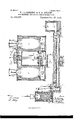
3 Sheets-Sheet 1. N. LILIENBERG 8v G. S. DWIGHT. GAS PRODUCER FOR ME'I'ALLURGIG OPERATIONS. No. 329,058.
Patented Oet. 27.1885.
(No Model.)
.tfilh l III m e m e mnm.
.| n C n Sie any.. e
N N l I/ .m a wf.
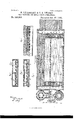
\ w e@ M 3 Sheets-Sheet 2.
Patented Oct. 27. 1885.
N. Patins. mwmuuwgnpw, wwangm. n.1;
(No Model N.VLILIENBERG a. G. s. DWIGHT. GAS PRODUCER FOR METALLURGIC OPERATIONS. No. 329,058.
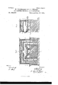
(No Model.) 3 Sheets-Sheet 3.
N.'L1L1ENBERG au G. s. DWIGHT. GAYS PRODUCER FOR METALLURGIG OPERATIONS.
No. 329,058. Patented Oct. 27, 1885.
tol
. tion of the apparatus.
UNirnn STATES PATENT Garros.
NILs LILIENBERG ann GEORGE SPRINGDWIGHT, or New Youn, n. "Y.
vrGAS-PRODUCER FOR ll/iELT'LLURGICv OPERATIONS.
SPECIFICATION forming part of Letters Patent Nof329,( )58, datedv October 27, 1885.
' Application sled Fabi-news1, less. serial No. 157,199. (no model.)
.To all whom it may concern.-
Beit known that we,N1Ls' LILIENBERG and GEORGE S. wienr, ofthe city and State of New York, have invented an Improvementin Gas-Producers for Metallurgie Operations, of which the following is a specification. The object of this invention is to-eonsume fuel gradually and produce a heating-gas containing a large volume of hydrogen, and to raisethis gas to a high temperature previous to its combustion in the presence of highlyheated atmospheric air, and also to make use of the heated gases, in their progress to the chimney, for heating up the air-blast and gases,- so asto economize the heat, and to produce an intense flame adapted to the melting of iron, steel, or other metals.
'In the drawings, b'igure ll is a vertieal sec- Fig. 2 is a crosssection through the generators atthe line .n a'.
- Fig. Sis a cross-section through the iiues at the line a l. Fig. 4 is a cross-section at the line c d. Fig.- 5 is a cross-section at 'the line ef. Fig. 6 is a cross-section at 1` 1, Fig; 1, through the" meltingfurnace. Fig. 7 is asec- -tion oi' the same at the line 2 2, Fig. 6; and
Fig. 8 is a plan View partially in section. y
G G represent two generators, which are preferably circular inform, and made of brick-work within metallic cases. The upper and lower portions of each generator are contracted, and there is a due, h, around the upv per portion of such generator, with lateral Aopenings into the generator, and two escapelues, h h2, pass oit' toward eachother, and between them is a lateral line, ha, passing oft' to l a descending iiue, 7and thence to the chimney, as hereinafter described. Above the .ilues 7L h2 h8 there is a dome, k, into which' steam is supplied from any suitable boiler, and within this dome is a movable valve, k', actuated by a rod, t', rock-shaft i?, and lever and handle t3, and there is a counter-weight, a", upon the rock-shaft i, which serves to insure the complete movement of the valve and hold it in either position. This valve k is hollowpandfof a length adapted to extend across and connect the upper ends of the ilues hl, as shown in Fig. 2, or it may be moved into the position shown by dotted lines to open' the communication between the tlues h2 h3. It is now to be understood that when this v'alve Yis in the position shown in steam from the dome k passes down through the iues hgh into the generator G', and down' through 5 5 the fuel in the same, so. that the steamis decomposed, theoxygen 'combining with the iu-. candescent fuel, and the hydrogen, commingled with carbonio oxide and other-products,v of
combustion, passing off, as hereinafter de- '6o scribed. During this same time the fuel in the generator G is being consumed and its heat intensified by air supplied at the bottom 'and'passing up through the fuel, the products I of combustion going by the lues lz, h through the valve k to the flue h, and away by the descending flue h4. moved, the. operations .are' reversed,A and the heating-gas is generated in G while the lire'. is being intensified 'in TF-nel 'issuppliedige'f'7ov riodically to these generators, vas required,by
a hopper, G?, to the generator G', and a hopper,
G3, tothe generator G. Each hopper is provided with a movable bottom, g, at its lower end operated by a rod, g.
nication between the hoppers and the generators. When depressed,the fuel is discharged from the hoppers to the generators: rlhelower part of each generator is contracted, and there 8o is an annular air-pipe, Z, beneath this contraction, and there is a chamber, L, below each generator, forming an ash-pit, and also a gas# line. To ,the flue or chamber L, below the generator G, is connectedra branch pipe, L3, 85
and to-the chamber L, belowthe generator G', is connected the'ueU. These dues L2 and L3 lead to the gaspipe L4. There are valves Za Z in the branch pipes LBLZ, respectively. lThe valves Z3 Z6 are connected by a rod, i4, and this 9o` is moved by a lever, Z5, and shaft il, and these are made so that when one valve is withdrawn to open the branch pipe L3 the valve to the branch pipe L2 is closed, and vice versa. 'ZB is a valve in the pipe L4 for closing the outlet of 95 Agas from the generators.
Whewthesteain-.valve lc. is
These movable bottoms when raised act asvalves to .close the commulhese valves are prefer- 10o such a manner that by movingthe lever l5 and shaft i7 the four valves Z3 Z6 and nn are simultaneously operated. When n is closed, nztis open to admit air into the generator G, and 5 the gas-valve Z" is simultaneously closed,'the gas-valve l being opened. In this position of the valve air will be passing in by the valve n* into the generator G to intensify the tire, and the heating-gas generated in G will be passing o" by the valve Z. When the lever Z5 and shaft il are moved and the positions of the valves reversed, the fire will be intensified in G by air admitted by the valven, and the heating-gas from the generator G will pass o by the valve Z".
It wi-ll be observed by reference to Fig. 2 that 'each chamber L beneath the generator is sufficiently large for a heap of ashes therein to accumulate and support the fuel in the generator, andthe air issuing from the annular pipe l passes downwardly into this chamber and asciende through the fuel, so thattthe combustion thereof is rendered perfect. heating-gas is being produced in agenerator, the gases pass down into such chamber L, and are led away, as aforesaid.
At a suitable distance from the generators.
there is an open hearth or furnace for the metallurgie operations. XVe prefer to make use of a hearth, 0, having a discharge-trough, o, at one end, the hearth being made of silieious or basic materials within a casing or car,o,on wheels o, which rest upon a track, o, and can be moved back or forward thereon.
We make use of a furnace-casing, P, snpported by the vbars and tie-rods p, andwithin these are `fire-brick partitions, forming inlet- -iiues p 1." and outlet-dues pf' p. The inletflues p p extend across above the hearth O, and there isa central opening and a deflector, by which the dame is directed downwardly upon the Imaterials to be melted upon the hearth O,and the dame and products of combustion pass away by the dues p p.
`Upon reference to the cross-section; Fig. 6, and the longitudinal section, Fig. 7, it will be seen that the iiues pp2 pp are at opposite sides of the'hearth 0, and t-hat this hearth is introduced into an opening provided for it 'cromwiseof the furnace. When this hearth =O `is rolled into its place,a luting of clay is'to be applied all around upon its upper edges, vandthe hearth is vto ybe raised up bodily,so :that the luting is compressed against and unites with the stationary portions of :the rruace,and'the 'bearers o5 are to be slipped in beneath the-hearth Oto lretain it i n the elevated position. W hen thehearth requires to be re- 'lined or frepaired, the bearers o are to be rcymovednnd the hearth O allowed to drop down lwith its wheels upon the track. This breaks away vthe luting and allows the hearth to be easily rolled'out from beneath the stationary portions ofthe-furnace. The arches, provided 65 withstoppexs at o, give access to the hearth O for introducing the material to be melted and for stirring the same. It is now to be understood that heating-gas is to be admitted through t-he flue p2 and air through the fiue p', and these combine and burn together in an intense flame as they pass through the opening beneath the deflector Q. The'gas is deriVed from the pipe L, and both the air and the gas are in a highly-heated condition before commingling and burning. The fines s t and chimney R,through which the product-s ofv combustion ascend, are about midway between the furnace P and the generators G and G', and at one side of ranges of fines passing horizontally, or nearly so, between such generators and the furnace. The products of combustion descending by the dues p pi from the furnace, and the products of combustion descending by the flue h from the generators, are led to the chimney R,and in their passage thereto the heat is transferred to the air and gases, respectively, reaching the furnace P through the dues pp2, so that 'the products of combustion escaping up the chimney R are comparatively cool. To accomplish this object the waste heat from the generators, as it passes down the due h, enters a transverse passage-way,S, and from that passes into the numerous horizontal flues s', and these ilues s open into a flue, s", leading across beneath them'tothe base of the chimney. In likemanner the'products of combustion from the furnace P descend by theflues p p into the transvenleehannel T, and from there pass by the numerous fines t to the transverse flue t beneath them to the base of the chimney. There is a range, U V, of pu merons horizontal fiuesplaced intermediately to the dues s t and extending nearly the whole length between the cross-ehannel S and the cross-chaunel T. Half of these u es are allotted to ai r, the y other -half to gas. The gas from the pipe-L passes into the cross flue or channel'V; thenc' through the dues V up into the cross due o'r channel V, and by the longitudinal flue 1?.
into the bottom portion ot' the ascending tine p to the furnace, as aforesaid, and in its travel said gas becomes lu'ghly heated by its lprox-- imity to theflues s t. In passes in through a grating, due orchannel, U, ues U to the cross flue or channel U, and by the longitudinal channelu to the` base of the ue p', the air becomes highlyheatod-from the proximity of the ilues so that the airand gases are highly heated and combustion is very perfect when the air and gases burn together over the hearth, nsbcfre like manner the air U', into a cross" and through the numerous described. Ii'theproductsofcombustionpissing away from the gcncratorsG G by the due li are not perfectly consumed, atmospheric air may be admitted into the cross-channel S, so that any carbouic oxide may be consumed and increase the heat in the lilies s'. shown gratings at s", through which such air may be admitted.
lt will new be apparent that this apparatus We havev is `adapted to the furnishing of a heating-gas continuously to the hearth O, because the dampers can be changed instantaneously and the steam directed through the generator G or G while the other generator is being heated up.
We are aware that a generator has been employed for the production of aheating-gas to be used in metallurgie operations, and that steam has been caused to pass down through the incandescent fuel while producing this heating-gas, and the temperature of the fuel has been augmented by shutting off the steam and admitting atmospheric air.
We claim as our inventionl. The generators G G', having fiues h h' h2 h3, in combination with the steam-dome and the slide-valve within the dome, and means for actuating such valve, substantially as specified.' f
. 2. The generators G G', the chambers L beneath the same, and the annular air-pipes Z, in combination with the air-pipes n m and valves n' a2, the gas-pipes L2 L3, the valves Z3 Z6, and mechanism for operating the same, substantially as set forth.
3. The combination of the generators G G' and iiues h' h2 h3 with the steam-supply and valve k', the air-pipes n Z, the chambers L beneath the generators, the gas-pipes L2 L3, the air and gas valves, and mechanism for actuating the same, substantially as set forth.
4. 'Ihe combination, with two adjacent generators and mechanism, substantially as specied, for admitting steam and air alternately, of a furnace or hearth for metallurgie operations, and connections for conveying the gases from the generators, and adjacent iiues for heating the atmospheric air in its passage to the furnace, so that the gas and heated air commingle and burn at a central point over the hearth, and uesr for conveying away lthe products of combustion from the furnace, substantially as specified.
5. The combination, with two adjacent generators for alternately producing a heatinggas by steam passed through incandescent fuel, of a furnace for metallurgie operations, flues for conveyingthe gas from either of the generators to the furnace, and contiguous-fines through which air passes to the furnace, and
Afor metallurgie operations, the ilues ss for the waste heat from the generators, the iiues t t forthewastc heat from the furnace, achimney, and the flues V V' for gas, and the iiues U U3 for air, the same being contiguous to the flues through which the products of combustion pass, so that the air and gas reach the metallurgie furnace in a highly-heated condition, substantially as specified.
7. The adjacent generators G G', having iiues h, and the iues h' h2, escape-flue h3, and means for supplying steam and heating the generators alternately for the production of a heating-gas, in combination with flues for the waste products of combustion, adjacent flues for air and gas, the flues P' P2 P3 P4, the deiiector Q, and the hearth O, for metallurgie operations, there being an opening beneath the deflector and over the hearth, at which point the gas and air commingle and burn, substantially as specified.
8. In an apparatus for producing gas for metallurgie operations, the combination of two adjacent gas-generators,flues h' h2 h3, for the products of combustion, and a valve for the admission-of steam, air-pipes, and pipes for conveying away the gases, and valves for 'the respective pipes, and flues by which the generators are alternately heated up and gas produced, and a furnace or hearth for metallurgie operations, and air and gas flues leading from the generators to the furnace, substantially as specified, whereby a heating-gas is produced nearly continuously, and supplied, together with heated air, to the metallurgie furnace, substantially as specified.
Signed by us this 10th day of February, A.
Publications (1)
| Publication Number | Publication Date |
|---|---|
| US329058A true US329058A (en) | 1885-10-27 |
Family
ID=2398168
Family Applications (1)
| Application Number | Title | Priority Date | Filing Date |
|---|---|---|---|
| US329058D Expired - Lifetime US329058A (en) | Peters |
Country Status (1)
| Country | Link |
|---|---|
| US (1) | US329058A (en) |
-
0
- US US329058D patent/US329058A/en not_active Expired - Lifetime
Similar Documents
| Publication | Publication Date | Title |
|---|---|---|
| US329058A (en) | Peters | |
| US363945A (en) | Beinhold boeklen | |
| US447916A (en) | stewart | |
| US406637A (en) | Administratrix of | |
| US370957A (en) | lipsey | |
| US404404A (en) | Apparatus for the manufacture of fuel and illuminating gas | |
| US339471A (en) | Process of and apparatus for manufacturing gas | |
| US339472A (en) | Process of and apparatus for manufacturing gas | |
| US412678A (en) | Gas-generator | |
| US376835A (en) | Apparatus for the manufacture of gas | |
| US397397A (en) | Apparatus for the manufacture of gas | |
| US294534A (en) | Apparatus foe manufacturing gas | |
| US491066A (en) | archer | |
| US263985A (en) | spbinger | |
| US289279A (en) | Leadley | |
| US360973A (en) | Hot-blast stove | |
| US290926A (en) | Process of and apparatus for manufacturing gas | |
| US330122A (en) | Illuminating gas | |
| US404207A (en) | Process of and apparatus for the manufacture of gas | |
| US387676A (en) | dwight | |
| US452697A (en) | e elliott | |
| US507981A (en) | Gas-generating apparatus | |
| US418615A (en) | Apparatus for the manufacture of gas | |
| US334700A (en) | geangee | |
| US404208A (en) | Apparatus for the manufacture of gas |