US3290578A - Multi-phase converter including a harmonic filter - Google Patents
Multi-phase converter including a harmonic filter Download PDFInfo
- Publication number
- US3290578A US3290578A US269479A US26947963A US3290578A US 3290578 A US3290578 A US 3290578A US 269479 A US269479 A US 269479A US 26947963 A US26947963 A US 26947963A US 3290578 A US3290578 A US 3290578A
- Authority
- US
- United States
- Prior art keywords
- filter
- tuned
- harmonics
- phase
- harmonic
- Prior art date
- Legal status (The legal status is an assumption and is not a legal conclusion. Google has not performed a legal analysis and makes no representation as to the accuracy of the status listed.)
- Expired - Lifetime
Links
- 238000009434 installation Methods 0.000 claims description 22
- 238000004804 winding Methods 0.000 description 31
- 230000001052 transient effect Effects 0.000 description 5
- 239000003990 capacitor Substances 0.000 description 4
- 230000000694 effects Effects 0.000 description 3
- 238000010304 firing Methods 0.000 description 3
- 239000013598 vector Substances 0.000 description 3
- 238000013016 damping Methods 0.000 description 2
- 230000001360 synchronised effect Effects 0.000 description 2
- 230000005540 biological transmission Effects 0.000 description 1
- 230000007547 defect Effects 0.000 description 1
- 238000010586 diagram Methods 0.000 description 1
- 238000006073 displacement reaction Methods 0.000 description 1
- 238000001914 filtration Methods 0.000 description 1
- 238000009499 grossing Methods 0.000 description 1
- 230000004048 modification Effects 0.000 description 1
- 238000012986 modification Methods 0.000 description 1
- 230000010355 oscillation Effects 0.000 description 1
- 230000003534 oscillatory effect Effects 0.000 description 1
- 230000002028 premature Effects 0.000 description 1
- 238000011084 recovery Methods 0.000 description 1
- 230000002441 reversible effect Effects 0.000 description 1
- 239000004065 semiconductor Substances 0.000 description 1
- 230000003068 static effect Effects 0.000 description 1
- 230000009466 transformation Effects 0.000 description 1
- 230000001960 triggered effect Effects 0.000 description 1
Images

Classifications
-
- H—ELECTRICITY
- H02—GENERATION; CONVERSION OR DISTRIBUTION OF ELECTRIC POWER
- H02M—APPARATUS FOR CONVERSION BETWEEN AC AND AC, BETWEEN AC AND DC, OR BETWEEN DC AND DC, AND FOR USE WITH MAINS OR SIMILAR POWER SUPPLY SYSTEMS; CONVERSION OF DC OR AC INPUT POWER INTO SURGE OUTPUT POWER; CONTROL OR REGULATION THEREOF
- H02M1/00—Details of apparatus for conversion
- H02M1/14—Arrangements for reducing ripples from DC input or output
- H02M1/146—Arrangements for reducing ripples from DC input or output using discharge tubes
Definitions
- the invention consists in an electrical harmonic filter for connection across a transmission line carrying an electrical signal having an alternating component, comprising a circuit having at least two parallel arms, tuned to different harmonics of the fundamental frequency of said signal component, a capacitative reactance connected in parallel with said circuit and of such electrical parameter that it is in parallel resonance with said circuit at a frequency which is higher than the resonance frequency f of that arm which is tuned to the higher or highest of said different harmonics and does not coincide with a harmonic of said fundamental frequency higher than said frequency 1.
- the invention consists in a convertor installation arranged for the exchange of power between an A.C. and a DC. system, wherein a harmonic filter according to the preceding paragraph is connected across the or each phase of said A.C. system, across the or each phase of said A.C. system and the D.C. terminals, or across the D.C. terminals alone, said filter connected across the DC. terminals presenting a low impedance to the lowest D.C. ripple frequency.
- the invention consists in a convertor installation arranged for the exchange of power between a multiphase A.C. and a DC. system, said convertor comprising a bridge circuit having a plurality of controlled rectifying devices, and a transformer connected between the A.C. system and said devices, wherein a harmonic filter according to the penultimate paragraph is connected across each phase of primary, secondary or tertiary windings of said transformer.
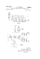
- FIG. 1 is a circuit diagram of the basic components of a 3-phase mercury-arc convertor installation including a filter according to the invention
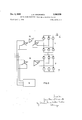
- FIG. 2 shows the impedance-frequency characteristic of the filter
- FIG. 3 shows a modification invention
- FIG. 4 shows a mercury-arc convertor installation in which a filter according to the invention is connected to a tertiary Winding of a transformer
- FIG. 5 shows a rnulti-bridge mercury-arc convertor installation.
- a 3- phase star-delta connected transformer has its starconnecte-d winding 10a connected to a 3-phase A.C. supply 11 and its delta-connected winding 10b connected to a 3-phase mercury-arc convertor bridge 12, consisting of six valves 1261-12).
- the convertor bridge 12 is connected to a DC. line 13 through a smoothing choke 14.
- a three-phase harmonic com filter 15 is connected of a filter according to the has a capacitative reactance 3,290,578 Patented Dec. 6, 1966 across the winding 10a of the transformer 10; the filter 15 has one branch per phase, the three identical branches 15a-15c being star-conectecl.
- Each branch such as 15a has a plurality of parallel arms such as 16, each of which consists of a resistance 17, an inductance 18 and a capacitance 19 connected in series.
- each branch 20 connected in parallel with the said arms.
- the inductance 18 and capacitance 19 of one arm of each branch of the filter are arranged for this arm to resonate at the lowest harmonic expected to occur which is usually the 5th harmonic.
- the inductances and capacitances of the other arms are arranged for the respective arms to resonate at the next higher expected harmonics, such as the 7th, 11th, 13th, 17th, 19th, 23rd and 25th harmonic.
- the capacitative reactance 20 of each branch of the filter is arranged so that it is in parallel resonance with the remainder of its branch at a frequency intermediate the highest harmonic frequency for which a resonant arm is provided and the frequency of the next higher harmonic expected.
- the highest harmonic to which an arm 16 is tun-ed is the 25th
- the next higher harmonic expected to occur is the 29th
- the fundamental frequency of the A.C. supply 11 is 50 c.p.s.
- the three capacitative reactan-ces 20 are each made of such a value that each branch Isa-15c of the filter 15- resonates at a frequency greater than 1250 c.p.s. and less than 1450 c.p.s.
- FIG. 2 The effect of the capacitative reactance 20, and'hence one of the advantages of the filter according to the invention, is shown in FIG. 2. It will be seen that the filter presents a low impedance to the expected harmonics above the highest harmonic to which an arm 16 is tuned, such as the 29th, 31st, 35th and 37th harmonic. For comparison, the dotted line shows the impedance characteristic over the last-mentioned range of higher harmonics for a filter not provided with the capacitative reactance 20.
- the number of parallel arms such as 16 to be provided for dealing with specific ones of the lower harmonics depends on the extent to which these harmonics are present in the A.C. wave form and the degree to which it is necessary or desirable to eliminate them in any particular installation.
- resistors such as the resistors 17, will usually unavoidably be present, and these may be deliberately increased to a small extent for greater damping of transients at the expense of higher effective filter impedance at the expected harmonic frequencies.
- the voltage at the points of connec tion of the filter to the A.C. supply 11 and the current in the A.C. system are substantially sine-waves at fundamental frequency.
- the effective commutating reactance of the converter is virtually the transformer leakage reactance only, and does not include that of the A.C. supply, which may therefore be of high impedance if desired.
- the net leading reactive power required to provide, for example, unity power factor at the points of connection of the filter is partly or wholly supplied by the leading current drawn by the filter at fundamental frequency, and is moreover less than the value which would be required by a synchronous or static capacitor alone instead of the filter.
- a resistor 21 may be connected in series with the capacitor 20 which should have a value such that it reduces the total impedance of the filter at the highest harmonic to which an arm such as 16 of the filter is tuned, viz: in the example shown, the peak between the 25th and 29th harmonic in FIG. 2. Adjacent peaks will thereby also be reduce-d to some extent.
- This resistor 21 is also valuable in reducing the oscillatory peak transient voltages obtained across the filter due, for example, to opening or closing a circuit breaker in the supply 11.
- the power dissipation in such a resistor due to current in the capacitor 20 at the fundamental frequency may be excessive, and this may be reduced by the provision of an inductor 22 connected across this resistor. This inductor, however, must not be so small as to appreciably change the damping effect of the resistor 21.
- the filter 15 may be connected across the terminals of the winding 1% of the transformer (viz: the A.C. terminals of the converter 12) the arrangement being otherwise as in FIG. 1.
- the convertor commutating reactance is theoretically zero, so that its commutation or overlap angle is zero and its power factor can approach unity.
- the current flowing in the transformer and A.C. system is then a sine wave, and moreover can be either at unity power factor or at leading power factor if the reactive power of the filter is sufficient.
- the terminal voltage of the transformer winding 1% may be equal to or greater than the terminal voltage of the winding a (on the basis of a 1:1 transformation ratio) and the size of the transformer may be reduced by, say 5% or more, compared with that required in the usual arrangements. With practical filters according to the invention, these conditions may be approached.
- the reverse voltage of the valves of the converter 12 at their current zero may be of very small amplitude at small firing angles, though its rate of rise is rapid.
- the recovery voltage amplitude becomes large and its rise time may be excessively small causing valve backfire. For this reason this last mentioned arrangement is less desirable.
- the filter may be connected to a tertiary winding 10c on the transformer 10, as shown in FIG. 4.
- this winding may be designed to work at a lower voltage than the other windings in, for example, a high voltage system, resulting in cheaper switchgear and the possibility of providing a synchronous capacitor in parallel with the filter to augment the reactive power.
- a filter according to the invention is provided in a mercury-arc convertor installation having two convertor bridges 12, 12' connected in series on the D.C. side, the corresponding primary windings 10a, 11111 of transformers 10, 10' being connected in parallel.
- the transformers 10, 10 are arranged with staggered phase vectors, so that the resultant currents in the A.C. system contain only the 11th, 13th, 23rd, 25th, etc., harmonics, in addition to the desired fundamental frequency.
- staggered phase vectors is meant an arrangement in which the groups of vectors of the voltages in n transformer wind-ings each having p phases, are relatively displaced in phase by 360/2 np degrees.
- each transformer may be provided with Cir a tertiary winding which may be connected together, the filter then being connected across them, or an inter-star or zig-zag arrangement may be employed.
- the tertiary reactance should preferably be approximately zero.
- the two bridges tend to produce mutual interference when operating as inver-tors, since at certain instances in the cycle the transient current change in one bridge causes resulting transient voltages on the A.C. side of the system due to the common A.C. system impedance, these transient voltages being transferred to the other transformer and tending to cause premature firing of the valves of the convertor connected to it.
- a filter according to the invention viz: one branch such as 15a in FIG. 1 may also be connected across the D.C. line 13 to reduce harmonic interference on this side of the installation; it has negligible effect on the convertor performance if the choke 14 is used between the convertor 12 and the D.C. line 13.
- the expected current harmonics are of frequencies 6, 12, 18, etc., times the fundamental supply frequency if one bridge such as 12 is used.
- Resonant arms, such as 16 may, for example, be used for and therefore tuned to, the 6th and 12th harmonics, and the capacitative reactance 20 arranged for parallel resonance with the remainder of the filter at a frequency of about 15 times the fundamental supply frequency.
- converters have been described and illustrated employing grid-controlled mercury-arc valves, it will be understood that other triggered rectifying devices may alternatively be used, e.g., semiconductor gated diodes.
- said converter installation comprising a plurality of controlled rectifying devices connected together as a bridge circuit
- a multi-phase transformer connected between the A.C. system and said devices, said transformer comprising multi-phase primary, secondary and tertiary windings, and
- harmonic filter connected across the said tertiary winding for substantially removing a plurality of predetermined harmonics of the said predetermined fundamental frequency
- the harmonic filter comprisa plurality of filter branches respectively connected across the phases of the said tertiary winding; each filter branch comprising plurality of tuned circuits connected in parallel with each other, which plurality is less than the plurality of predetermined harmonics to be removed by the filter, each tuned circuit being tuned to a different said predetermined harmonic, and a capacitive reactance connected in parallel with all the said tuned circuits of the filter branch, said capacitive reactance being in parallel resonance with all the said tuned circuits in the filter branch at a frequency between the highest one of the said harmonies to which any said tuned circuit is tuned and the next higher one of the said predetermined harmonies.
- a multi-phase converter installation for the exchange of electrical power between a multi-phase A.C. system 3,290,578 6 operating at a predetermined fundamental frequency and parallel resonance with all the said tuned circuits a D.C. system, the converter installation comprising 'at a frequency between the highest frequency to a multi-phase transformer having a primary winding which any said tuned circuit is tuned and the freand a secondary winding,
- a converter installation for the exchange of power means connecting the said bridge circuit between the between a multi-phase A.C. system operating at a presaid secondary Winding and the said D.C. system, determined fundamental frequency and a D.C. system, means connecting the said primary winding to the said said converter installation comprising A.C. system, and 10 a plurality of controlled rectifying devices connected a harmonic filter for substantially removing each one together as a first bridge circuit,
- the said harfirst and second multi-phase transformers respectively monic filter comprising connected between the A.C. system and corresponda plurality of filter branches each connected across a ing ones of said first and second bridge circuits, each respective said phase of the A.C. system, and each transformer having a primary, a secondary, and a said filter branch comprising tertiary winding, the tertiary windings of the two a pluarlity of parallel-connected tuned circuits, which transformers being connected together, and
- each filter branch comprising branch at a frequency between the highest one of a plurality of tuned circuits connected in parallel with the said harmonics to which any said tuned circuit each other, which plurality is less than the said pluis tuned and the next higher one of the said harrality of predetermined harmonics to be removed,
- a multi-phase converter installation for the exeach tuned circuit being tuned to a respective one of the said predetermined harmonics
- each tuned circuit being tuned to the frequency of a respective one of the said predetermined D.C. ripple signals
- the said capacitive reactance being arranged to be in tem, the converter installation comprising said capacitive reactance being in parallel resonance a multi-phase transformer having a primary winding with all the said tuned circuits in the filter branch and a secondary winding, at a frequency between the highest one of the said a plurality of controlled rectifying devices connected harmonics to which any said tuned circuit in the together as a bridge circuit, filter branch is tuned and the next higher one of the means connecting the said bridge circuit between the 40 said predetermined harmonics.
Landscapes
- Engineering & Computer Science (AREA)
- Power Engineering (AREA)
- Supply And Distribution Of Alternating Current (AREA)
Description
Dec. 6, 1966 .1. D. AINSWORTH 3,290,578
MULTI-PHASE CONVERTER INCLUDING A HARMONIC FILTER Filed April 1, 1963 5 Sheets-Sheet l F WP u I I I I I l l Dec. 6, 1966 J. D. AINSWORTH 3,290,578
PHASE CONVERTER INCLUDING A HARMONIC FILTER MULTI 3 Sheets-Sheet 2 Filed April 1, 1965 2'9 3'1 x SUPPLY FREQUENCY) FREQUENCY mMNL W mkmw w 1956 J. D. AINSWORTH 3,290,578
MULTI-PHASE CONVERTER INCLUDING A HARMONIC FILTER Filed April 1, 1963 5 Sheets-Sheet 3 FIG.5
W AW G5 IMLVSSSWJWJMMNM United States Patent Office 3,290,578 MULTI-PHASE CONVERTER INCLUDING A HARMONIC FILTER John Desmond Ainsworth, Stafford, England, asslgnor to The English Electric Company Limited, London, England, a British company Filed Apr. 1, 1963, Ser. No. 269,479 Claims priority, application Great Britain, Apr. 6, 1962, 13,410/ 62 4 Claims. (Cl. 321-9) This invention relates to electrical harmonic filters and to electrical apparatus, for example, mercury-arc convertor installations incorporating such filters.
According to one aspect, the invention consists in an electrical harmonic filter for connection across a transmission line carrying an electrical signal having an alternating component, comprising a circuit having at least two parallel arms, tuned to different harmonics of the fundamental frequency of said signal component, a capacitative reactance connected in parallel with said circuit and of such electrical parameter that it is in parallel resonance with said circuit at a frequency which is higher than the resonance frequency f of that arm which is tuned to the higher or highest of said different harmonics and does not coincide with a harmonic of said fundamental frequency higher than said frequency 1.
According to another aspect, the invention consists in a convertor installation arranged for the exchange of power between an A.C. and a DC. system, wherein a harmonic filter according to the preceding paragraph is connected across the or each phase of said A.C. system, across the or each phase of said A.C. system and the D.C. terminals, or across the D.C. terminals alone, said filter connected across the DC. terminals presenting a low impedance to the lowest D.C. ripple frequency.
According to another aspect, the invention consists in a convertor installation arranged for the exchange of power between a multiphase A.C. and a DC. system, said convertor comprising a bridge circuit having a plurality of controlled rectifying devices, and a transformer connected between the A.C. system and said devices, wherein a harmonic filter according to the penultimate paragraph is connected across each phase of primary, secondary or tertiary windings of said transformer.
Preferred embodiments of a filter according to the invention and various arrangements of electrical apparatus, in the form of mercury-arc convertor installations, containing such filters will now be described, by way of example, with reference to the accompanying drawings. In the drawings:
FIG. 1 is a circuit diagram of the basic components of a 3-phase mercury-arc convertor installation including a filter according to the invention;
FIG. 2 shows the impedance-frequency characteristic of the filter;
FIG. 3 shows a modification invention;
FIG. 4 shows a mercury-arc convertor installation in which a filter according to the invention is connected to a tertiary Winding of a transformer; and
FIG. 5 shows a rnulti-bridge mercury-arc convertor installation.
In the convertor installation shown in FIG. 1, a 3- phase star-delta connected transformer has its starconnecte-d winding 10a connected to a 3-phase A.C. supply 11 and its delta-connected winding 10b connected to a 3-phase mercury-arc convertor bridge 12, consisting of six valves 1261-12). The convertor bridge 12 is connected to a DC. line 13 through a smoothing choke 14.
A three-phase harmonic com filter 15 is connected of a filter according to the has a capacitative reactance 3,290,578 Patented Dec. 6, 1966 across the winding 10a of the transformer 10; the filter 15 has one branch per phase, the three identical branches 15a-15c being star-conectecl. Each branch such as 15a has a plurality of parallel arms such as 16, each of which consists of a resistance 17, an inductance 18 and a capacitance 19 connected in series. In addition, each branch 20 connected in parallel with the said arms.
The inductance 18 and capacitance 19 of one arm of each branch of the filter are arranged for this arm to resonate at the lowest harmonic expected to occur which is usually the 5th harmonic. Likewise the inductances and capacitances of the other arms are arranged for the respective arms to resonate at the next higher expected harmonics, such as the 7th, 11th, 13th, 17th, 19th, 23rd and 25th harmonic.
The capacitative reactance 20 of each branch of the filter is arranged so that it is in parallel resonance with the remainder of its branch at a frequency intermediate the highest harmonic frequency for which a resonant arm is provided and the frequency of the next higher harmonic expected. Thus, if the highest harmonic to which an arm 16 is tun-ed is the 25th, the next higher harmonic expected to occur is the 29th and the fundamental frequency of the A.C. supply 11 is 50 c.p.s., the three capacitative reactan-ces 20 are each made of such a value that each branch Isa-15c of the filter 15- resonates at a frequency greater than 1250 c.p.s. and less than 1450 c.p.s.
The effect of the capacitative reactance 20, and'hence one of the advantages of the filter according to the invention, is shown in FIG. 2. It will be seen that the filter presents a low impedance to the expected harmonics above the highest harmonic to which an arm 16 is tuned, such as the 29th, 31st, 35th and 37th harmonic. For comparison, the dotted line shows the impedance characteristic over the last-mentioned range of higher harmonics for a filter not provided with the capacitative reactance 20.
Whilst these higher harmonics may, of course, be filtered out by providing further arms 16, each tuned to one of these higher harmonics, and whilst the sizes of the components of these arms may be progressively reduced as the harmonic number increases, there is nevertheless a practical economic limit to the number of such arms to be provided. The filter according to the invention thus provides a technically acceptable and considerably less expensive device for filtering out these higher harmonics.
The number of parallel arms such as 16 to be provided for dealing with specific ones of the lower harmonics depends on the extent to which these harmonics are present in the A.C. wave form and the degree to which it is necessary or desirable to eliminate them in any particular installation.
In a practical case, resistors, such as the resistors 17, will usually unavoidably be present, and these may be deliberately increased to a small extent for greater damping of transients at the expense of higher effective filter impedance at the expected harmonic frequencies.
In practice, with the filter connected as shown in FIG. 1, it is found that the voltage at the points of connec tion of the filter to the A.C. supply 11 and the current in the A.C. system are substantially sine-waves at fundamental frequency. Moreover, the effective commutating reactance of the converter is virtually the transformer leakage reactance only, and does not include that of the A.C. supply, which may therefore be of high impedance if desired. Furthermore, the net leading reactive power required to provide, for example, unity power factor at the points of connection of the filter is partly or wholly supplied by the leading current drawn by the filter at fundamental frequency, and is moreover less than the value which would be required by a synchronous or static capacitor alone instead of the filter.
If desired, as shown in FIG. 3, a resistor 21 may be connected in series with the capacitor 20 which should have a value such that it reduces the total impedance of the filter at the highest harmonic to which an arm such as 16 of the filter is tuned, viz: in the example shown, the peak between the 25th and 29th harmonic in FIG. 2. Adjacent peaks will thereby also be reduce-d to some extent. This resistor 21 is also valuable in reducing the oscillatory peak transient voltages obtained across the filter due, for example, to opening or closing a circuit breaker in the supply 11. In practice the power dissipation in such a resistor due to current in the capacitor 20 at the fundamental frequency, may be excessive, and this may be reduced by the provision of an inductor 22 connected across this resistor. This inductor, however, must not be so small as to appreciably change the damping effect of the resistor 21.
In an alternative arrangement, the filter 15 may be connected across the terminals of the winding 1% of the transformer (viz: the A.C. terminals of the converter 12) the arrangement being otherwise as in FIG. 1.
In this arrangement with an ideal filter, the convertor commutating reactance is theoretically zero, so that its commutation or overlap angle is zero and its power factor can approach unity. The current flowing in the transformer and A.C. system is then a sine wave, and moreover can be either at unity power factor or at leading power factor if the reactive power of the filter is sufficient. In the latter case the terminal voltage of the transformer winding 1% may be equal to or greater than the terminal voltage of the winding a (on the basis of a 1:1 transformation ratio) and the size of the transformer may be reduced by, say 5% or more, compared with that required in the usual arrangements. With practical filters according to the invention, these conditions may be approached.
The reverse voltage of the valves of the converter 12 at their current zero may be of very small amplitude at small firing angles, though its rate of rise is rapid. At convertor grid firing angles of the order of 90, the recovery voltage amplitude becomes large and its rise time may be excessively small causing valve backfire. For this reason this last mentioned arrangement is less desirable.
As a further alternative to the arrangement shown in FIG. 1, the filter may be connected to a tertiary winding 10c on the transformer 10, as shown in FIG. 4.
The main advantages of the use of such a tertiary winding for this purpose are that this winding may be designed to work at a lower voltage than the other windings in, for example, a high voltage system, resulting in cheaper switchgear and the possibility of providing a synchronous capacitor in parallel with the filter to augment the reactive power.
In FIGURE 5 a filter according to the invention is provided in a mercury-arc convertor installation having two convertor bridges 12, 12' connected in series on the D.C. side, the corresponding primary windings 10a, 11111 of transformers 10, 10' being connected in parallel. In this installation the transformers 10, 10 are arranged with staggered phase vectors, so that the resultant currents in the A.C. system contain only the 11th, 13th, 23rd, 25th, etc., harmonics, in addition to the desired fundamental frequency.
By staggered phase vectors is meant an arrangement in which the groups of vectors of the voltages in n transformer wind-ings each having p phases, are relatively displaced in phase by 360/2 np degrees.
Thus, where two 3- phase transformers 10, 10 are used, this relative phase displacement must be and this is conveniently obtained by using star-connected windings 10b and delta-connected windings 1017, the star-star transformer 10' employing a tertiary delta-winding 10c. Alternatively, each transformer may be provided with Cir a tertiary winding which may be connected together, the filter then being connected across them, or an inter-star or zig-zag arrangement may be employed. The tertiary reactance should preferably be approximately zero.
In such a 2-convertor bridge arrangement, the two bridges tend to produce mutual interference when operating as inver-tors, since at certain instances in the cycle the transient current change in one bridge causes resulting transient voltages on the A.C. side of the system due to the common A.C. system impedance, these transient voltages being transferred to the other transformer and tending to cause premature firing of the valves of the convertor connected to it.
With ordinary filters this phenomenon leads to repeated commutation failure and may, in fact, make operation impossible. This defect is avoided or at least substantially reduced by the use of a filter according to the invention connected to the common point in the A.C. system, since the lower frequency resonant arms deal with the bulk of the transients and the cap-acitative reactance such as 20, suppresses the fast transient components without giving rise to undesired oscillations.
A filter according to the invention, viz: one branch such as 15a in FIG. 1 may also be connected across the D.C. line 13 to reduce harmonic interference on this side of the installation; it has negligible effect on the convertor performance if the choke 14 is used between the convertor 12 and the D.C. line 13.
In this case the expected current harmonics are of frequencies 6, 12, 18, etc., times the fundamental supply frequency if one bridge such as 12 is used. Resonant arms, such as 16, may, for example, be used for and therefore tuned to, the 6th and 12th harmonics, and the capacitative reactance 20 arranged for parallel resonance with the remainder of the filter at a frequency of about 15 times the fundamental supply frequency.
Although converters have been described and illustrated employing grid-controlled mercury-arc valves, it will be understood that other triggered rectifying devices may alternatively be used, e.g., semiconductor gated diodes.
Iclaim:
1. A converter installation for the exchange of power between a multi-phase A.C. system, operating at a predetermined fundamental frequency, and a D.C. system,
' said converter installation comprising a plurality of controlled rectifying devices connected together as a bridge circuit,
a multi-phase transformer connected between the A.C. system and said devices, said transformer comprising multi-phase primary, secondary and tertiary windings, and
a harmonic filter connected across the said tertiary winding for substantially removing a plurality of predetermined harmonics of the said predetermined fundamental frequency, the harmonic filter comprisa plurality of filter branches respectively connected across the phases of the said tertiary winding; each filter branch comprising plurality of tuned circuits connected in parallel with each other, which plurality is less than the plurality of predetermined harmonics to be removed by the filter, each tuned circuit being tuned to a different said predetermined harmonic, and a capacitive reactance connected in parallel with all the said tuned circuits of the filter branch, said capacitive reactance being in parallel resonance with all the said tuned circuits in the filter branch at a frequency between the highest one of the said harmonies to which any said tuned circuit is tuned and the next higher one of the said predetermined harmonies. 2. A multi-phase converter installation for the exchange of electrical power between a multi-phase A.C. system 3,290,578 6 operating at a predetermined fundamental frequency and parallel resonance with all the said tuned circuits a D.C. system, the converter installation comprising 'at a frequency between the highest frequency to a multi-phase transformer having a primary winding which any said tuned circuit is tuned and the freand a secondary winding,
quency of the next higher frequency D.C. ripple a plurality of controlled rectifying devices connected 5 signal.
together as a bridge circuit, 4. A converter installation for the exchange of power means connecting the said bridge circuit between the between a multi-phase A.C. system operating at a presaid secondary Winding and the said D.C. system, determined fundamental frequency and a D.C. system, means connecting the said primary winding to the said said converter installation comprising A.C. system, and 10 a plurality of controlled rectifying devices connected a harmonic filter for substantially removing each one together as a first bridge circuit,
of the harmonics of the said predetermined fundaa plurality of further controlled rectifying devices conmental frequency in the series 5th, 7th, 11th, 13th, nected together as a second bridge circuit,
17th, 19th, 23rd, 25th harmonics, the said harfirst and second multi-phase transformers respectively monic filter comprising connected between the A.C. system and corresponda plurality of filter branches each connected across a ing ones of said first and second bridge circuits, each respective said phase of the A.C. system, and each transformer having a primary, a secondary, and a said filter branch comprising tertiary winding, the tertiary windings of the two a pluarlity of parallel-connected tuned circuits, which transformers being connected together, and
plurality is less than the nurnltler of said harmonics a harmonic filter connected across each said tertiary in the said series, each tuned circuit being tuned to winding for substantially removing a plurality of a respective one of the said harmonics, predetermined harmonics of the said predetermined each filter branch also including a capacitive reactance fundamental frequency, the harmonic filter comprisconnected in parallel with all the tuned circuits of ing the branch, a plurality of filter branches respectively connected said capacitive reactance being arranged to be in paralacross the phases of the respective said tertiary windlel resonance with all the said tuned circuits in the ing, each filter branch comprising branch at a frequency between the highest one of a plurality of tuned circuits connected in parallel with the said harmonics to which any said tuned circuit each other, which plurality is less than the said pluis tuned and the next higher one of the said harrality of predetermined harmonics to be removed,
monics in the series. 3. A multi-phase converter installation for the exeach tuned circuit being tuned to a respective one of the said predetermined harmonics, and
change of power between an A.C. system operating at a a capacitive reactance connected in parallel with all predetermined fundamental fi'equency and a D.C. systhe said tuned circuits of the filter branch,
signals, each tuned circuit being tuned to the frequency of a respective one of the said predetermined D.C. ripple signals, and
a capacitive reactance connected in parallel with all the said tuned circuits,
the said capacitive reactance being arranged to be in tem, the converter installation comprising said capacitive reactance being in parallel resonance a multi-phase transformer having a primary winding with all the said tuned circuits in the filter branch and a secondary winding, at a frequency between the highest one of the said a plurality of controlled rectifying devices connected harmonics to which any said tuned circuit in the together as a bridge circuit, filter branch is tuned and the next higher one of the means connecting the said bridge circuit between the 40 said predetermined harmonics.
said secondary winding and the said D.C. system, means connecting the said primary winding to the References Clfed y the Examlllel' said l y and d th D C UNITED STATES PATENTS a armonic ter connecte across e sar systern for substantially removing each one of a plu- 32? 321-10 X man 321-9 rality of predetermlned D.C. ripple slgnals harmoni- 2 942 197 6/1960 M d a sen et al 33376 X cally related to the said fundamental frequency of 3 038 134 6/1962 Forssen the A.C. system, the harmonic filter including a plurality of tuned circuits connected in parallel, which FOREIGN PATENTS plurality is less than the said plurality of D.C. ripple 446,223 1936 Great Britain JOHN F. COUCH, Primary Examiner.
LLOYD MCCOLLUM, Examiner.
W, E A2 As s an E am r
Claims (1)
- 2. A MULTI-PHASE CONVERTER INSTALLATION FOR THE EXCHANGE OF ELECTRICAL POWER BETWEEN A MULTI-PHASE A.C. SYSTEM OPERATING AT A PREDETERMINED FUNDAMENTAL FREQUENCY AND A D.C. SYSTEM, THE CONVERTER INSTALLATION COMPRISING A MULTI-PHASE TRANSFORMER HAVING A PRIMARY WINDING AND A SECONDARY WINDING, A PLURALITY OF CONTROLLED RECTIFYING DEVICES CONNECTED TOGETHER AS A BRIDGE CIRCUIT, MEANS CONNECTING THE SAID BRIDGE CIRCUIT BETWEEN THE SAID SECONDARY WINDING AND THE SAID D.C. SYSTEM, MEANS CONNECTING THE SAID PRIMARY WINDING TO THE SAID A.C. SYSTEM, AND A HARMONIC FILTER FOR SUBSTANTIALLY REMOVING EACH ONE OF THE HARMONIES OF THE SAID PREDETERMINED FUNDAMENTAL FREQUENCY IN THE SERIES 5TH, 7TH, 11TH, 13TH, 17TH, 19TH, 23RD, 25TH ... HARMONICS, THE SAID HARMONIC FILTER COMPRISING A PLURALITY OF FILTER BRANCHES EACH CONNECTED ACROSS A RESPECTIVE SAID PHASE OF THE A.C. SYSTEM, AND EACH SAID FILTER BRANCH COMPRISING A PLURALITY OF PARALLEL-CONNECTED TUNED CIRCUITS, WHICH PLURALITY IS LESS THAN THE NUMBER OF SAID HARMONICS IN THE SAID SERIES, EACH TUNED CIRCUIT BEING TUNED TO A RESPECTIVE ONE OF THE SAID HARMONICS, EACH FILTER BRANCH ALSO INCLUDING A CAPACITIVE REACTANCE CONNECTED IN PARALLEL WITH ALL THE TUNED CIRCUITS OF THE BRANCH, SAID CAPACITIVE REACTANCE BEING ARRANGED TO BE IN PARALLEL RESONANCE WITH ALL THE SAID TUNED CIRCUITS IN THE BRANCH AT A FREQUENCY BETWEEN THE HIGHEST ONE OF THE SAID HARMONICS TO WHICH ANY SAID TUNED CIRCUIT IS TUNED AND THE NEXT HIGHER ONE OF THE SAID HARMONICS IN THE SERIES.
Applications Claiming Priority (1)
| Application Number | Priority Date | Filing Date | Title |
|---|---|---|---|
| GB13410/62A GB1034341A (en) | 1962-04-06 | 1962-04-06 | Improvements in and relating to electrical filters |
Publications (1)
| Publication Number | Publication Date |
|---|---|
| US3290578A true US3290578A (en) | 1966-12-06 |
Family
ID=10022438
Family Applications (1)
| Application Number | Title | Priority Date | Filing Date |
|---|---|---|---|
| US269479A Expired - Lifetime US3290578A (en) | 1962-04-06 | 1963-04-01 | Multi-phase converter including a harmonic filter |
Country Status (2)
| Country | Link |
|---|---|
| US (1) | US3290578A (en) |
| GB (1) | GB1034341A (en) |
Cited By (21)
| Publication number | Priority date | Publication date | Assignee | Title |
|---|---|---|---|---|
| US3440516A (en) * | 1966-07-11 | 1969-04-22 | Westinghouse Electric Corp | Transformer and capacitor apparatus for three-phase electrical systems |
| US3453526A (en) * | 1966-08-25 | 1969-07-01 | English Electric Co Ltd | Regulated d.c. power supply with frequency-selective ripple removal |
| US3501686A (en) * | 1968-08-22 | 1970-03-17 | Asea Ab | Control device for a filter circuit for a static inverter |
| US3535542A (en) * | 1969-02-20 | 1970-10-20 | Hydro Quebec | Interconnected harmonic filters for electric power lines |
| US3555291A (en) * | 1968-05-16 | 1971-01-12 | Gen Electric | Power system filter |
| US3711760A (en) * | 1971-06-30 | 1973-01-16 | Westinghouse Electric Corp | Rectifier-transformer system |
| US3813593A (en) * | 1973-05-04 | 1974-05-28 | Gen Electric | Reduction of turbine generator shaft torques |
| US3881137A (en) * | 1973-01-17 | 1975-04-29 | Ass Elect Ind | Frequency selective damping circuits |
| US4228492A (en) * | 1977-11-04 | 1980-10-14 | Brown, Boveri & Cie Ag | Circuit arrangement and method for the compensation of harmonic currents |
| US4630163A (en) * | 1982-09-02 | 1986-12-16 | Efi Corporation | Method and apparatus for a transient-suppression network |
| US4710735A (en) * | 1985-01-08 | 1987-12-01 | Bbc Brown, Boveri & Company, Limited | Absorption circuit |
| US4862341A (en) * | 1988-11-02 | 1989-08-29 | Sundstrand Corporation | Filter for variable speed, constant frequency electrical system |
| US5036292A (en) * | 1990-02-16 | 1991-07-30 | Audio Research Corporation | Decoupled electrolytic capacitor |
| US5446642A (en) * | 1992-05-11 | 1995-08-29 | Electric Power Research Institute, Inc. | Harmonic blocking converter system |
| US5515264A (en) * | 1992-05-11 | 1996-05-07 | Electric Power Research Institute, Inc. | Optimized high power voltage sourced inverter system |
| US6160442A (en) * | 1998-03-30 | 2000-12-12 | Asea Brown Boveri Ag | Load-side filter arrangement for a converter circuit arrangement |
| US20100033028A1 (en) * | 2006-11-21 | 2010-02-11 | Siemens Aktiengesellschaft | Device for flexible power transmission and deicing of a high-voltage power line by means of direct current |
| EP2164159A1 (en) * | 2008-09-12 | 2010-03-17 | Vestas Wind Systems A/S | Low-voltage harmonic filter for full-scale converter systems |
| BE1021310B1 (en) * | 2014-06-14 | 2015-10-28 | Spica Nv | BROADBAND STOP FILTER FOR LOW-VOLTAGE LINE COMMUNICATION. |
| US20160049880A1 (en) * | 2013-08-29 | 2016-02-18 | Korea Electric Power Corporation | High-voltage direct current converter |
| EP3334022A1 (en) * | 2016-12-08 | 2018-06-13 | Audi Ag | Motor vehicle and converter for a motor vehicle |
Citations (5)
| Publication number | Priority date | Publication date | Assignee | Title |
|---|---|---|---|---|
| US2015534A (en) * | 1933-05-27 | 1935-09-24 | Westinghouse Electric & Mfg Co | Filter system for mercury-arc rectifiers |
| GB446223A (en) * | 1934-04-21 | 1936-04-27 | British Thomson Houston Co Ltd | Improvements in and relating to means for eliminating harmonics from an alternating current network |
| US2820189A (en) * | 1956-08-14 | 1958-01-14 | Asea Ab | Static current converter using voltage commutation |
| US2942197A (en) * | 1956-06-26 | 1960-06-21 | Bell Telephone Labor Inc | Amplitude limiting circuit |
| US3038134A (en) * | 1958-01-18 | 1962-06-05 | Asea Ab | Means for reducing the harmonic currents in a static converter plant |
-
1962
- 1962-04-06 GB GB13410/62A patent/GB1034341A/en not_active Expired
-
1963
- 1963-04-01 US US269479A patent/US3290578A/en not_active Expired - Lifetime
Patent Citations (5)
| Publication number | Priority date | Publication date | Assignee | Title |
|---|---|---|---|---|
| US2015534A (en) * | 1933-05-27 | 1935-09-24 | Westinghouse Electric & Mfg Co | Filter system for mercury-arc rectifiers |
| GB446223A (en) * | 1934-04-21 | 1936-04-27 | British Thomson Houston Co Ltd | Improvements in and relating to means for eliminating harmonics from an alternating current network |
| US2942197A (en) * | 1956-06-26 | 1960-06-21 | Bell Telephone Labor Inc | Amplitude limiting circuit |
| US2820189A (en) * | 1956-08-14 | 1958-01-14 | Asea Ab | Static current converter using voltage commutation |
| US3038134A (en) * | 1958-01-18 | 1962-06-05 | Asea Ab | Means for reducing the harmonic currents in a static converter plant |
Cited By (27)
| Publication number | Priority date | Publication date | Assignee | Title |
|---|---|---|---|---|
| US3440516A (en) * | 1966-07-11 | 1969-04-22 | Westinghouse Electric Corp | Transformer and capacitor apparatus for three-phase electrical systems |
| US3453526A (en) * | 1966-08-25 | 1969-07-01 | English Electric Co Ltd | Regulated d.c. power supply with frequency-selective ripple removal |
| US3555291A (en) * | 1968-05-16 | 1971-01-12 | Gen Electric | Power system filter |
| US3501686A (en) * | 1968-08-22 | 1970-03-17 | Asea Ab | Control device for a filter circuit for a static inverter |
| US3535542A (en) * | 1969-02-20 | 1970-10-20 | Hydro Quebec | Interconnected harmonic filters for electric power lines |
| US3711760A (en) * | 1971-06-30 | 1973-01-16 | Westinghouse Electric Corp | Rectifier-transformer system |
| US3881137A (en) * | 1973-01-17 | 1975-04-29 | Ass Elect Ind | Frequency selective damping circuits |
| US3813593A (en) * | 1973-05-04 | 1974-05-28 | Gen Electric | Reduction of turbine generator shaft torques |
| US4228492A (en) * | 1977-11-04 | 1980-10-14 | Brown, Boveri & Cie Ag | Circuit arrangement and method for the compensation of harmonic currents |
| US4630163A (en) * | 1982-09-02 | 1986-12-16 | Efi Corporation | Method and apparatus for a transient-suppression network |
| US4710735A (en) * | 1985-01-08 | 1987-12-01 | Bbc Brown, Boveri & Company, Limited | Absorption circuit |
| US4862341A (en) * | 1988-11-02 | 1989-08-29 | Sundstrand Corporation | Filter for variable speed, constant frequency electrical system |
| US5036292A (en) * | 1990-02-16 | 1991-07-30 | Audio Research Corporation | Decoupled electrolytic capacitor |
| US5446642A (en) * | 1992-05-11 | 1995-08-29 | Electric Power Research Institute, Inc. | Harmonic blocking converter system |
| US5515264A (en) * | 1992-05-11 | 1996-05-07 | Electric Power Research Institute, Inc. | Optimized high power voltage sourced inverter system |
| US6160442A (en) * | 1998-03-30 | 2000-12-12 | Asea Brown Boveri Ag | Load-side filter arrangement for a converter circuit arrangement |
| GB2456460B (en) * | 2006-11-21 | 2012-08-08 | Siemens Ag | [Apparatus for flexible power transmission and for deicing of a high-voltage line by means of direct current |
| US20100033028A1 (en) * | 2006-11-21 | 2010-02-11 | Siemens Aktiengesellschaft | Device for flexible power transmission and deicing of a high-voltage power line by means of direct current |
| US8264102B2 (en) * | 2006-11-21 | 2012-09-11 | Siemens Aktiengesellschaft | Device for flexible power transmission and deicing of a high-voltage power line by means of direct current |
| EP2164159A1 (en) * | 2008-09-12 | 2010-03-17 | Vestas Wind Systems A/S | Low-voltage harmonic filter for full-scale converter systems |
| US20100118568A1 (en) * | 2008-09-12 | 2010-05-13 | Vestas Wind Systems A/S | Low-Voltage Harmonic Filter for Full-Scale Converter Systems |
| US8466661B2 (en) | 2008-09-12 | 2013-06-18 | Vestas Wind Systems A/S | Low-voltage harmonic filter for full-scale converter systems |
| US20160049880A1 (en) * | 2013-08-29 | 2016-02-18 | Korea Electric Power Corporation | High-voltage direct current converter |
| US9692311B2 (en) * | 2013-08-29 | 2017-06-27 | Korea Electric Power Corporation | High-voltage direct current converter including a 12-pulse diode recitifier connected in series with a voltage-source converter |
| BE1021310B1 (en) * | 2014-06-14 | 2015-10-28 | Spica Nv | BROADBAND STOP FILTER FOR LOW-VOLTAGE LINE COMMUNICATION. |
| EP3334022A1 (en) * | 2016-12-08 | 2018-06-13 | Audi Ag | Motor vehicle and converter for a motor vehicle |
| US10263505B2 (en) | 2016-12-08 | 2019-04-16 | Audi Ag | Filtering of alternating voltage components in the intermediate circuit of a rectifier device of a motor vehicle |
Also Published As
| Publication number | Publication date |
|---|---|
| GB1034341A (en) | 1966-06-29 |
Similar Documents
| Publication | Publication Date | Title |
|---|---|---|
| US3290578A (en) | Multi-phase converter including a harmonic filter | |
| US4308575A (en) | Power source system | |
| US5905642A (en) | Apparatus and method to reduce common mode voltage from current source drives | |
| US4366532A (en) | AC/DC or DC/AC Converter system with improved AC-line harmonic reduction | |
| CN103503268B (en) | Wind energy converter | |
| Stratford | Harmonic pollution on power systems-a change in philosophy | |
| US5124904A (en) | Optimized 18-pulse type AC/DC, or DC/AC, converter system | |
| US4623830A (en) | Alternating-current machine drive | |
| JP2008533958A (en) | 12-pulse high-voltage DC transmission | |
| US11342861B2 (en) | Method and apparatus to mitigate DC bus over-voltages on common AC bus systems utilizing DC and AC drives | |
| US4439823A (en) | Converting multiphase power from one frequency to another using current waveforms | |
| US3641417A (en) | Input filter circuit for cycloconverter apparatus | |
| US3038134A (en) | Means for reducing the harmonic currents in a static converter plant | |
| US3535542A (en) | Interconnected harmonic filters for electric power lines | |
| Peng et al. | A study of active power filters using quad-series voltage-source PWM converters for harmonic compensation | |
| Rahouma et al. | A medium-voltage SiC flying capacitor converter design for 25-kV distribution systems | |
| CN214228124U (en) | Intermediate frequency power supply | |
| EP4430644A1 (en) | Transformer system for a direct current converter system | |
| US3440516A (en) | Transformer and capacitor apparatus for three-phase electrical systems | |
| Oguchi et al. | Voltage-phase shifting effect of three-phase harmonic canceling reactors and their applications to three-level diode rectifiers | |
| Jamil et al. | Harmonics in adjustable speed drives: causes, effects, and solutions | |
| EP0118418B1 (en) | Circuit arrangement for compensation of fast changing reactive power, in particular on the point of consumers, which generate harmonics | |
| CN223666046U (en) | Multi-machine parallel system | |
| US20250023481A1 (en) | Power conversion device | |
| GB2242792A (en) | Reactive power generator |