US3290572A - Direct current motor with transistorized power supply - Google Patents
Direct current motor with transistorized power supply Download PDFInfo
- Publication number
- US3290572A US3290572A US380266A US38026664A US3290572A US 3290572 A US3290572 A US 3290572A US 380266 A US380266 A US 380266A US 38026664 A US38026664 A US 38026664A US 3290572 A US3290572 A US 3290572A
- Authority
- US
- United States
- Prior art keywords
- armature
- voltage
- motor
- transistor
- tachometer
- Prior art date
- Legal status (The legal status is an assumption and is not a legal conclusion. Google has not performed a legal analysis and makes no representation as to the accuracy of the status listed.)
- Expired - Lifetime
Links
- 230000005291 magnetic effect Effects 0.000 claims description 28
- 230000001105 regulatory effect Effects 0.000 claims description 21
- 230000009471 action Effects 0.000 claims description 3
- 230000001276 controlling effect Effects 0.000 claims description 3
- 230000003534 oscillatory effect Effects 0.000 claims description 2
- 238000004804 winding Methods 0.000 description 41
- 239000003990 capacitor Substances 0.000 description 9
- 230000001965 increasing effect Effects 0.000 description 8
- 230000000903 blocking effect Effects 0.000 description 5
- 238000010586 diagram Methods 0.000 description 5
- 229910000859 α-Fe Inorganic materials 0.000 description 5
- 230000005284 excitation Effects 0.000 description 4
- 230000004907 flux Effects 0.000 description 4
- 230000006698 induction Effects 0.000 description 4
- XEEYBQQBJWHFJM-UHFFFAOYSA-N Iron Chemical compound [Fe] XEEYBQQBJWHFJM-UHFFFAOYSA-N 0.000 description 3
- 230000033228 biological regulation Effects 0.000 description 3
- 125000004122 cyclic group Chemical group 0.000 description 3
- 230000001939 inductive effect Effects 0.000 description 3
- 230000010355 oscillation Effects 0.000 description 3
- 229920006395 saturated elastomer Polymers 0.000 description 3
- 235000013290 Sagittaria latifolia Nutrition 0.000 description 2
- 235000015246 common arrowhead Nutrition 0.000 description 2
- 230000000694 effects Effects 0.000 description 2
- 230000006872 improvement Effects 0.000 description 2
- 238000000034 method Methods 0.000 description 2
- 230000008569 process Effects 0.000 description 2
- 235000009434 Actinidia chinensis Nutrition 0.000 description 1
- 244000298697 Actinidia deliciosa Species 0.000 description 1
- 235000009436 Actinidia deliciosa Nutrition 0.000 description 1
- 230000006978 adaptation Effects 0.000 description 1
- 230000015556 catabolic process Effects 0.000 description 1
- 238000010276 construction Methods 0.000 description 1
- 230000005294 ferromagnetic effect Effects 0.000 description 1
- 230000017525 heat dissipation Effects 0.000 description 1
- 229910052742 iron Inorganic materials 0.000 description 1
- 238000012423 maintenance Methods 0.000 description 1
- 230000004048 modification Effects 0.000 description 1
- 238000012986 modification Methods 0.000 description 1
- 230000009467 reduction Effects 0.000 description 1
- 230000000087 stabilizing effect Effects 0.000 description 1
Images

Classifications
-
- H—ELECTRICITY
- H02—GENERATION; CONVERSION OR DISTRIBUTION OF ELECTRIC POWER
- H02P—CONTROL OR REGULATION OF ELECTRIC MOTORS, ELECTRIC GENERATORS OR DYNAMO-ELECTRIC CONVERTERS; CONTROLLING TRANSFORMERS, REACTORS OR CHOKE COILS
- H02P6/00—Arrangements for controlling synchronous motors or other dynamo-electric motors using electronic commutation dependent on the rotor position; Electronic commutators therefor
- H02P6/06—Arrangements for speed regulation of a single motor wherein the motor speed is measured and compared with a given physical value so as to adjust the motor speed
-
- H—ELECTRICITY
- H02—GENERATION; CONVERSION OR DISTRIBUTION OF ELECTRIC POWER
- H02K—DYNAMO-ELECTRIC MACHINES
- H02K29/00—Motors or generators having non-mechanical commutating devices, e.g. discharge tubes or semiconductor devices
- H02K29/06—Motors or generators having non-mechanical commutating devices, e.g. discharge tubes or semiconductor devices with position sensing devices
- H02K29/12—Motors or generators having non-mechanical commutating devices, e.g. discharge tubes or semiconductor devices with position sensing devices using detecting coils using the machine windings as detecting coil
-
- H—ELECTRICITY
- H02—GENERATION; CONVERSION OR DISTRIBUTION OF ELECTRIC POWER
- H02P—CONTROL OR REGULATION OF ELECTRIC MOTORS, ELECTRIC GENERATORS OR DYNAMO-ELECTRIC CONVERTERS; CONTROLLING TRANSFORMERS, REACTORS OR CHOKE COILS
- H02P6/00—Arrangements for controlling synchronous motors or other dynamo-electric motors using electronic commutation dependent on the rotor position; Electronic commutators therefor
- H02P6/08—Arrangements for controlling the speed or torque of a single motor
-
- H—ELECTRICITY
- H02—GENERATION; CONVERSION OR DISTRIBUTION OF ELECTRIC POWER
- H02P—CONTROL OR REGULATION OF ELECTRIC MOTORS, ELECTRIC GENERATORS OR DYNAMO-ELECTRIC CONVERTERS; CONTROLLING TRANSFORMERS, REACTORS OR CHOKE COILS
- H02P6/00—Arrangements for controlling synchronous motors or other dynamo-electric motors using electronic commutation dependent on the rotor position; Electronic commutators therefor
- H02P6/10—Arrangements for controlling torque ripple, e.g. providing reduced torque ripple
Definitions
- the present invention relates to a direct current (DC) motor in which armature coils or windings are connected to a transistorized power supply.
- DC. motors whose armature windings are connected to a transistorized power supply, in which the transistors are controlled by a control circuit as a function of the instantaneous angular position of the rotor relative to the stator.
- the control circuit is a feed back connection which includes coils and a control transistor and induces control coils which regulate the armature transistors.
- the rotational speed can be regulated by means of a centrifugal switch.
- a centrifugal switch besides being a relatively expensive piece of equipment, is subject to breakdown and requires a certain amount of maintenance. It is, therefore, the primary object of the present invention to provide a way in which such a centrifugal switch can be eliminated in favor of simpler and far more reliable means.
- the present invention resides in a DC.
- the motor whose armature windings are connected to a transistorized power supply, in which the armature transistors are controlled by a control circuit in dependence on the instantaneous angular position of the rotor and stator relative to each other, the control circuit being constituted by a feed back connection consisting of coils and a control transistor, and in which, according to the present invention, there is applied to the control circuit a potential which is a function of the rotational speed of the motor and which is generated by a permanent magnetic motor field which rotates with the rotor, such that the control circuit becomes ineffective at a predetermined rotational speed by interrupting the feeding of power to the armature windings.
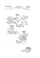
- FIGURE 1 is a perspective diagrammatic representation of a motor according to the present invention and shows certain ones of the electromechanical components.
- FIGURE 2 is a circuit diagram of the motor control arrangement according to the present invention.
- FIGURE 3 is a graph showing the timed relationship of a voltage effective in the motor control circuit according to the present invention.
- FIGURE 4 is a circuit diagram of another embodiment of a motor control arrangement according to the instant invention.
- FIGURE 5 is a circuit diagram showing a part of a modified motor control arrangement according to the present invention.
- FIGURE 6 is a circuit diagram showing a part of yet another modified motor control arrangement according to the present invention.
- FIG. 1 shows a rotor 17 mounted on a shaft 16, this rotor being, for the sake of simplicity, represented as a rotating, cylindrical magnet whose polarity is shown at N and S.
- the stationary armature windings being the operating windings, are indicated at 1, 2,
- the cyclic sequence of the electronic control of the transistors is brought about by the motor itself.
- carrier 18 Mounted on the shaft 16 for rotation therewith is carrier 18 carrying a block 19, made of highfrequency iron or ferrite and having the shape of an arcuate segment.
- the purpose of this segment 19 is to conduct the magnetic flux of a high-frequency oscillator (this being the feed back), consisting of the coils 35 and 36 which are wound on a core 37, 38, the control transistor 15, and the capacitors 16 and 17, cyclically from core 38 to the cores of the control windings 31, 32, 33, 34.
- control windings 31, 32, 33, 34 are rectified by means of respective diodes 21, 22, 23, 24, and are applied, as control voltages, to the bases of the armature transistors 11, 12, 13, 14.
- the emitter-collector path of each transistor thus remains conductive as long as a control voltage is applied to it, i.e., so long as there is a magnetic flux passing through the respective control coil.
- the oscillator itself remains excited so long as the battery 5 is connected to the circuit by means of the switch 6.
- the transistor fed D.C. motor could, theoretically, continuously increase its rotational speed until its counter electromotive force is induced in the armature windings, if no provision were made for maintaining a given predetermined rotational speed.
- the rotational speed is limited by turning off the oscillator and hence the high-frequency control, this being done by applying to the base of the oscillator transistor a voltage which is proportional to the increasing rotational speed.
- This voltage will, for the sake of con venience, hereinafter be referred to as a tachometer voltage. Consequently, when there is no longer any regulation, the armature windings 1, 2, 3, 4, will no longer be fed with any current pulses, as a result of which the motor reduces its speed.
- the tachometer voltage i.e., the voltage which is proportional to the rotational speed of the motor
- the blocking voltage of the oscillator transistor drops below the blocking voltage of the oscillator transistor, and this will, in a manner of speaking, again turn on the oscillator and the high-frequency control becomes elfective once more.
- the motor therefore again has a driving pulse applied to it. This entire process is repeated, within narrow limits of course, so that the motor will run at what is, for all practical purposes, a constant speed.
- the cylindrical magnetic rotor 17 serves as the magnetic inductor of the tachometer generator which delivers the tachometer voltage, the same being induced in coils 26, 27, 28, 29, hereinafter referred to as tachometer coils, lying in the same slots as do the working windings 1, 2, 3, 4.
- the tachometer windings are connected, via respective rectifier diodes 46, 47, 48, 49, and a control potentiometer 51 to the so-called tachometer circuit such that the rectified voltage taken off potentiometer 51 is applied via a Zener diode 50 to the emitter-base path of the oscillator transistor 15, whereat it acts as a blocking voltage.
- the Zener diode maintains this blocking voltage constant at a value which is precisely of such amplitude as to stop the oscillation.
- the graph of FIGURE 3 shOWs the blocking voltage V which is limited by the Zener diode 50, this being a rectified sinusoidal voltage of a single exciter path of the tachometer generator.
- the rectified tachometer genera tor voltage can, for example, be so reduced by the potentiometer that the motor again has to increase its speed until the tachometer generator voltage increases and reaches the blocking voltage, whereupon the motor will be driven at the new, increased rotational speed. If this voltage is increased by the potentiometer, the rotational speed of the motor is reduced. In this way, the nominal r.p.m., i.e., the predetermined rotational speed at which the motor is to run, may be adjusted, within a wide range, by the potentiometer 51.
- FIGURE 4 is a circuit diagram of a further example of a motor fed by a transistorized power supply and speedregulated by a tachometer generator. While the circuit of FIGURE 4 is, in principle, similar to that described above, it differs somewhat in construction.
- the armature transistors 112, 113, 122, 123 are connected to form a bridge circuit having points a, b, c, a, the armature windings 110, 120, lying, serially connected, across one diagonal (b, d) of the bridge and two batteries 111, 121, being serially connected and lying across the other diagonal (a, c).
- the circuit includes two ganged switches 137, 137a, the former of which connects the negative terminal of the battery 111 to the collectors of the armature transistors 112 and 122, which are connected to point a of the bridge.
- Switch 137 also connects the high-frequency oscillator, which is a conventional feed back connected, transistorized high-frequency generator, connected as a three-point oscillator, to the battery 111, this oscillator being made to oscillate by feed back.
- the second switch 137a connects the positive terminal of battery 121 with the emitters of the armature transistors 113 and 123 which are connected to point of the bridge.
- the junction of the armature windings 110, 120 is connected to the junction of the bat- .teries 111 and 121, so as to complete the exciter current of the motor.
- the two armature windings 110, 120 are thus excited by the two batteries by means of the armature transistors which are connected in the bridge circuit.
- This cyclic excitation which here, too, is brought about by the magnetic inductive control and thus depends on the rotational speed of the motor, as described in conjunction with FIGURES 1 and 2, is caused by the fact that, during one complete rotor revolution, two current pulses, in opposition, flow through each of the two armature windings.
- there will be four current pulses during each revolution which four pulses create a pulsating, spatial field having the characteristics of a rotary field, it being this field which causes the rotation of the r-otor.
- a ferromagnetic, rotating flux-bridging element 144 preferably a ferrite and having an arcuate configuration similar to that of element 19 of FIGURE 1, is represented symbolically, in FIGURE 4, by the dashed line.
- This element 144 conducts the high-frequency magnetic flux in core 143, the same being a U-shaped yoke, made preferably of a ferrite, which flux is generated by the coil 140 of the resonant circuit of the oscillator, back through the control coils on the yoke.
- the direction of rotation of the magnetic rotor is given, both for structural and electrical reasons: the direction of rotation is given structurally by the fixed position of the rotor with respect to the element 144 which rotates with the rotor, and the direction of rotation is given for electrical reasons by the direction of the current through the armature windings,
- the control coil 114 of FIGURE 4 is subjected to high-frequency magnetic induction through the flux-bridging element 144.
- the induced high-frequency voltage is rectified by means of a diode 214 and smoothed by a capacitor 314.
- the thus rectified and smoothed voltage is applied, as a control voltage, to the base-emitter path of the armature transistor 112.
- the emitter-collector path of armature transistor 112 is thus rendered conductive, so that an exciter current can flow from one terminal of the battery 111 through the armature Winding 110 via the emitter-collector path of the armature transistor 112 and the closed switch 137, to the other terminal of battery 111.
- the armature is now so magnetized by the current flow that its magnetic field is displaced by with respect to the direction of the field of the magnetic rotor.
- the magnetic rotor thus receives a maximum torque depending on the instantaneous spatial orientation (90) and on the vectorial magnitude of the magnetic fields.
- the rotor starts its rotation, for example such that its N pole turns toward the nearest stationary S pole.
- the element 144 which has an arcuate length of 90, will have interrupted the induction of control coil 114 so that the exciter current through armature winding is likewise interrupted by the blocked armature transistor 112.
- the edge of the element 144 which, during the rotation, moves over the control coil 125, starts the inductive excitation of the control coil 125, while the trailing edge of the element will, after a further rotation of 90, interrupt the inductive excitation of the control coil 125.
- the exciter current through the armature winding 12%) induces an armature field in the direction of the arrow.
- the arrow head is intended, for example, to represent the S pole of a stationary armature field, the N pole of the magnetic rotorwhich at this instant is vertically orientedrotating in clock-wise direction with respect to the armature field.
- the N pole of the magnetic rotor then assumes its horizontal position, i.e., when it assumes the position as the S pole of the armature, the horizontal armature field is eliminated due to the switching effect by the element 144.
- the magnetic rotor is turned, in clock-wise direction, such that its N pole is in the vertical position of the excited S pole of the armature field.
- the vertical positioning of the N pole of the magnetic rotor eliminates the vertical armature S pole and is again excited, due to the change-over effected by the element 144, via the control coil 124, the diode 224, the transistor 122 and the armature winding 120, to a position represented by the rightwardly pointing, horizontal dashed arrow.
- the magnetic rotor After a further rotation of 90, in clock-wise direction, the magnetic rotor will have completed one complete revolution, and the rotor will continue to rotate, so long as the ganged switches 137, 137a, remain closed, with the armature being excited in the cyclic manner described above.
- the rotational speed of the motor is limited by means of a tachometer voltage.
- the tachometer windings 310, 320 of FIGURE 4 in which the tachometer voltage is induced by the N-S rotor magnet, will, in practice and as explained above in conjunction with FIGURES 1 and 2, lie in the same grooves as the armature windings 110, 120.
- the induced tachometer AC. voltage is rectified by the diodes 311 and 321 and smoothed by capacitor 322.
- the potentiometer 323 completes the tachometer circuit and allows the tachometer to be adjusted so that the motor speed may be regulated to any desired value.
- the adjustable tachometer voltage is applied, via a Zener diode 326, to the emitter-base circuit of a transistor 327, which, in this circuit, operates as a current amplifier.
- a Zener diode 326 As and when the tachometer voltage taken off potentiometer 323 has reached the threshold voltage of the Zener diode, such voltage is also applied to the base of the transistor 327 so that its emitter-collector path becomes conductive.
- the positive voltage of battery 121 is now applied to the base of the oscillator transistor 141 which, up to now, was connected solely to the negative terminal of battery 111 via a resistor 100.
- the base of the oscillator transistor 141 thus becomes currentless, as a result of which the oscillator frequency voltage is no longer generated.
- the motor is thus no longer controlled and energized so that its rotational speed drops. But this, in turn, drops the voltage applied to the Zener diode below the threshold voltage thereof, whereupon the oscillator is once more activated, which brings with it the control and energization of the motor. This process continues so that the motor is regulated to run at a certain speed, depending on the setting of the potentiometer 323.
- the speed regulation obtained with the circuit of FIG- URE 4 represents an improvement over that obtained with the arrangement of FIGURES l and 2 in that there is included a transistor 327 which has a greater effect on the oscillator.
- This means that the tachometer itself draws less power so that the over-all efficiency 'of the motor is increased, due to the fact that the tachometer is called upon to deliver but very little power.
- the power drawn by the tachometer is equal to the square of the particular tachometer voltage divided by the high-ohmic resistance of the potentiometer 323.
- the resistor 160 has a DC. voltage applied to it, which corresponds to the sum of the voltages of the serially connected batteries 111, 121.
- the resistor 100 is suitably designed insofar as its heat dissipation is concerned.
- FIGURE 5 shows a circuit by means of which the motor can be made to run at either one of two different regulated rotational speeds.
- the emitter-collector path of transistor 337 becomes conductive at a given tachometer DC. voltage, thereby short-circuiting the emitterbase path of the oscillator transistor 141.
- the ganged switches 137, 137a are closed, the battery 121 is connected to the Zener diode 326 via a limiting resistor 328.
- the voltage applied to the Zener diode now remains constant with respect to the higher battery voltage, which, however, may fluctuate during operation of the motor.
- the stablized voltage of the Zener diode is applied to a voltage divider which comprises a variable resistor 410, the same being connected in parallel with a switch 400, and a serially connected variable potentiometer 420. If the motor is to run at the higher of its two speeds, the switch is moved to its closed position H, thereby short-circuiting the resistor 410. Consequently, the stabilized divided voltage taken off potentiometer 420, i.e., across terminals 421 and 422, is relatively large, and the terminal 421 is positive with respect to the terminal 422, the latter being connected to the emitter of the transistor 337.
- the tachometer voltage which is induced, during the rotation of the motor, in tachometer winding 320, and is rectified by diode 321 and smoothed by capacitor 322, now has its polarity (see the and symbols) so connected in opposition to the stabilized tapped voltage that it becomes effective for opening the transistor 337 only when it has reached, and, more accurately, surpassed, the voltage taken off across the emitter and potentiometer slide. It will be seen that the amplitude of the positive voltage taken off potentiometer 420 is a measure of the greater of the two rotational speeds to which the motor is to be regulated.
- the motor is regulated to run at the lower of the two speeds by opening the switch 400, i.e., by moving it to the position N.
- the resistor 410 which is adjusted to the particular low speed desired, is now effective and the voltage which was heretofore set at the potentiometer is now reduced due to the increased voltage division. Due to the now greatly excessive tachometer counter voltage, the transistor will remain in its blocked state. The stator windings of the motor receive no current so that the speed of the motor drops. This speed reduction continues until the tachometer voltage becomes so low that there is no emitter-base current in transistor 337. The motor will then have assumed the lower of its two speeds.
- the tachometer generator operates practically without power inasmuch as its induced control voltage is exactly proportional to the motor rpm. and compensates one, or more, stabilized control voltages.
- the circuit of FIGURE 6 includes an oscillator which, as in the case of the above embodiments, has the conventional feed back three-point connection.
- a portion of the high-frequency energy in the resonant circuit 140, 142 is applied as feed back, via capacitor 145,to the baseemitter path of the transistor 141.
- This controls the transistor 141 and hence maintains the high-frequency oscillation.
- Connected in parallel with the base-emitter path of transistor 141 is the series connection of a capacitor 146 and a choke coil 147, the latter being wound on a ferrite core 149.
- This core is excited with direct current, by means of a further coil 148 and an adjustable resistor 150, by the tachometer generator of the motor, until, when a certain rotational speed is reached, the current will have increased to the point at which the core is electromagnetically saturated and the inductance of choke coil 147 disappears almost completely.
- the saturated choke coil offers no impedance to the feed back voltage, so that the same is short-circuited, across the emitter-base path of the transistor 141, via the capacitor 146 and the now inductanceless choke coil 147. There is no oscillator frequency since the saturated iron core choke coil shortcircuits the feed back voltage for the oscillator transistor.
- the rotational speed is increased by increasing the variable resistor 150, as a result of which the saturation current for the choke will not be attained until the tachometer voltage is greater.
- the saturable choke together with its coils 147, 148, can be eliminated if the saturation coil 148 is wound on the ferrite core 143 next to the resonant circuit coil of the oscillator.
- the capacitor 146 can then also be dispensed with.
- the core 143 is electromagnetically saturated so that the inductance of the resonant circuit coil 149 is reduced to zero, thereby eliminating the high-frequency oscillations.
- a DC. motor having a stator and a rotor
- the combination which comprises: means forming armature windings; a power supply having armature transistors connected to said windings; a control circuit connected to said armature transistors for controlling the same in dependence on the relative angular position between the stator and rotor, said control circuit being an oscillatory circuit incorporating a control transistor; means for producing a permanent magnetic motor field which rotates with the rotor; and speed regulating means connected to said control circuit for applying thereto a tachometer potential, which is generated by the inductor action of said magnetic motor field, which potential renders said control circuit ineffective at a given predetermined rotational speed by interrupting the feeding of power to said armature windings.
- said speed regulating means include an amplifier transistor the output of which is applied to the base circuit of said control transistor.
- said speed regulating means include a tachometer winding which is connected in series with and acts in opposition to a source of voltage constituting a bias, the base-emitter circuit of said intermediate transistor being connected across said bias such that upon attainment of said predetermined rotational speed said tachometer potential put out by said tachometer winding exceeds said bias.
- said regulating means render said control circuit inefiective at either one of two given predetermined rotational speeds
- said regulating means including a battery, a stabilizing resistor connected across said battery, two serially connected resistors connected across said battery, a tachometer winding, said tachometer winding lying in series with one of said two serially connected resistors, said one resistor being adjusted to regulate the higher of the two speeds, a switch connected across the other of said two serially connected resistors, said other resistor being adjusted to a value such that it, together with the resistance of said one resistor, provides the effective resistance for speed regulation at the lower of the 'two speeds when said switch is open, in consequence of which the motor may be regulated to run at either of said two speeds by opening or closing said switch.
- a DC. motor having armature windings, means for producing a permanent magnetic motor field which rotates With the rotor, a power supply having armature transistors connected to said windings, and a control circuit connected to said armature transistors for controlling the same in dependence on the relative angular position between the stator and rotor, said control circuit being a feed back circuit incorporating coils and a control transistor, the improvement which comprises rotational speed regulating means connected to said control circuit for applying thereto a potential which is generated by the inductor action of said magneticmotor field, which potential renders said control ineifective at a given predetermined rotational speed by interrupting the feeding of power to said armature windings.
Landscapes
- Engineering & Computer Science (AREA)
- Power Engineering (AREA)
- Control Of Motors That Do Not Use Commutators (AREA)
- Control Of Direct Current Motors (AREA)
- Motor And Converter Starters (AREA)
Description
1966 J. HARTMANN ETAL 3,
DIRECT CURRENT MOTOR WITH TRANSISTORIZED POWER SUPPLY Filed July 6, 1964 2 Sheets-Sheet 1 Jnve tors Julian fiortmmn Hehnmt kiwi? Fig. 3
D80 1966 J. HARTMANN ETAL 7 DIRECT CURRENT MOTOR WITH TRANSISTORIZED POWER SUPPLY Filed July 6, 1964 2 Sheets-Sheet 2 I50 32/ 5 Ema 322 #320 I40 [can Hartmann H L112 Mocza w maffl J enia rs Ll elm United States Patent Ofiice 10 Claims. (a. 318-438) The present invention relates to a direct current (DC) motor in which armature coils or windings are connected to a transistorized power supply.
There exist DC. motors whose armature windings are connected to a transistorized power supply, in which the transistors are controlled by a control circuit as a function of the instantaneous angular position of the rotor relative to the stator. The control circuit is a feed back connection which includes coils and a control transistor and induces control coils which regulate the armature transistors.
As with any motor, the rotational speed can be regulated by means of a centrifugal switch. Such a switch, besides being a relatively expensive piece of equipment, is subject to breakdown and requires a certain amount of maintenance. It is, therefore, the primary object of the present invention to provide a way in which such a centrifugal switch can be eliminated in favor of simpler and far more reliable means. With this basic object in view, the present invention resides in a DC. motor whose armature windings are connected to a transistorized power supply, in which the armature transistors are controlled by a control circuit in dependence on the instantaneous angular position of the rotor and stator relative to each other, the control circuit being constituted by a feed back connection consisting of coils and a control transistor, and in which, according to the present invention, there is applied to the control circuit a potential which is a function of the rotational speed of the motor and which is generated by a permanent magnetic motor field which rotates with the rotor, such that the control circuit becomes ineffective at a predetermined rotational speed by interrupting the feeding of power to the armature windings.
Additional objects and advantages of the present invention will become apparent upon consideration of the following description when taken in conjunction with the accompanying drawings in which:
FIGURE 1 is a perspective diagrammatic representation of a motor according to the present invention and shows certain ones of the electromechanical components.
FIGURE 2 is a circuit diagram of the motor control arrangement according to the present invention.
FIGURE 3 is a graph showing the timed relationship of a voltage effective in the motor control circuit according to the present invention.
FIGURE 4 is a circuit diagram of another embodiment of a motor control arrangement according to the instant invention.
FIGURE 5 is a circuit diagram showing a part of a modified motor control arrangement according to the present invention.
FIGURE 6 is a circuit diagram showing a part of yet another modified motor control arrangement according to the present invention.
Referring now to the drawing and to FIGURES 1 and 2 thereof in particular, the same shows a rotor 17 mounted on a shaft 16, this rotor being, for the sake of simplicity, represented as a rotating, cylindrical magnet whose polarity is shown at N and S. The stationary armature windings, being the operating windings, are indicated at 1, 2,
3,290,572 Patented Dec. 6, 1966 3, 4. These windings are connected to transistors 11, 12, 13, 14 (FIGURE 2) which, in accordance with the particular angular position of the magnetic rotor, cause D.C. pulses to flow through the windings, in cyclical sequence, such that the magnet rotor is, as in a rotating field, continuously subjected to an electromagnetic pull or torque, thereby to start the motor and to maintain the rotor in rotation so long as a battery 5 is switched in by closing of a switch 6.
The cyclic sequence of the electronic control of the transistors, these being hereinafter referred to as the armature transistors and which function as controlled switching transistors, is brought about by the motor itself. Mounted on the shaft 16 for rotation therewith is carrier 18 carrying a block 19, made of highfrequency iron or ferrite and having the shape of an arcuate segment. The purpose of this segment 19 is to conduct the magnetic flux of a high-frequency oscillator (this being the feed back), consisting of the coils 35 and 36 which are wound on a core 37, 38, the control transistor 15, and the capacitors 16 and 17, cyclically from core 38 to the cores of the control windings 31, 32, 33, 34. The high-frequency voltage induced in these control windings 31, 32, 33, 34, are rectified by means of respective diodes 21, 22, 23, 24, and are applied, as control voltages, to the bases of the armature transistors 11, 12, 13, 14. The emitter-collector path of each transistor thus remains conductive as long as a control voltage is applied to it, i.e., so long as there is a magnetic flux passing through the respective control coil. The oscillator itself, of course, remains excited so long as the battery 5 is connected to the circuit by means of the switch 6.
The transistor fed D.C. motor could, theoretically, continuously increase its rotational speed until its counter electromotive force is induced in the armature windings, if no provision were made for maintaining a given predetermined rotational speed. According to the present invention, the rotational speed is limited by turning off the oscillator and hence the high-frequency control, this being done by applying to the base of the oscillator transistor a voltage which is proportional to the increasing rotational speed. This voltage will, for the sake of con venience, hereinafter be referred to as a tachometer voltage. Consequently, when there is no longer any regulation, the armature windings 1, 2, 3, 4, will no longer be fed with any current pulses, as a result of which the motor reduces its speed. But as the rotational speed drops, the tachometer voltage, i.e., the voltage which is proportional to the rotational speed of the motor, drops below the blocking voltage of the oscillator transistor, and this will, in a manner of speaking, again turn on the oscillator and the high-frequency control becomes elfective once more. The motor therefore again has a driving pulse applied to it. This entire process is repeated, within narrow limits of course, so that the motor will run at what is, for all practical purposes, a constant speed.
The basic components by means of which the rotational speed of the motor is regulated, together with their function, will be explained in conjunction with FIGURES 1 and 2. The cylindrical magnetic rotor 17 serves as the magnetic inductor of the tachometer generator which delivers the tachometer voltage, the same being induced in coils 26, 27, 28, 29, hereinafter referred to as tachometer coils, lying in the same slots as do the working windings 1, 2, 3, 4. The tachometer windings are connected, via respective rectifier diodes 46, 47, 48, 49, and a control potentiometer 51 to the so-called tachometer circuit such that the rectified voltage taken off potentiometer 51 is applied via a Zener diode 50 to the emitter-base path of the oscillator transistor 15, whereat it acts as a blocking voltage. The Zener diode maintains this blocking voltage constant at a value which is precisely of such amplitude as to stop the oscillation.
The graph of FIGURE 3 shOWs the blocking voltage V which is limited by the Zener diode 50, this being a rectified sinusoidal voltage of a single exciter path of the tachometer generator. The rectified tachometer genera tor voltage can, for example, be so reduced by the potentiometer that the motor again has to increase its speed until the tachometer generator voltage increases and reaches the blocking voltage, whereupon the motor will be driven at the new, increased rotational speed. If this voltage is increased by the potentiometer, the rotational speed of the motor is reduced. In this way, the nominal r.p.m., i.e., the predetermined rotational speed at which the motor is to run, may be adjusted, within a wide range, by the potentiometer 51.
FIGURE 4 is a circuit diagram of a further example of a motor fed by a transistorized power supply and speedregulated by a tachometer generator. While the circuit of FIGURE 4 is, in principle, similar to that described above, it differs somewhat in construction. In the circuit of FIGURE 4, the armature transistors 112, 113, 122, 123, are connected to form a bridge circuit having points a, b, c, a, the armature windings 110, 120, lying, serially connected, across one diagonal (b, d) of the bridge and two batteries 111, 121, being serially connected and lying across the other diagonal (a, c).
The circuit includes two ganged switches 137, 137a, the former of which connects the negative terminal of the battery 111 to the collectors of the armature transistors 112 and 122, which are connected to point a of the bridge. Switch 137 also connects the high-frequency oscillator, which is a conventional feed back connected, transistorized high-frequency generator, connected as a three-point oscillator, to the battery 111, this oscillator being made to oscillate by feed back. The second switch 137a connects the positive terminal of battery 121 with the emitters of the armature transistors 113 and 123 which are connected to point of the bridge. The junction of the armature windings 110, 120 is connected to the junction of the bat- .teries 111 and 121, so as to complete the exciter current of the motor. The two armature windings 110, 120 are thus excited by the two batteries by means of the armature transistors which are connected in the bridge circuit. This cyclic excitation, which here, too, is brought about by the magnetic inductive control and thus depends on the rotational speed of the motor, as described in conjunction with FIGURES 1 and 2, is caused by the fact that, during one complete rotor revolution, two current pulses, in opposition, flow through each of the two armature windings. Thus, there will be four current pulses during each revolution, which four pulses create a pulsating, spatial field having the characteristics of a rotary field, it being this field which causes the rotation of the r-otor.
As in the case of a commutator-equipped DC motor, the motor would, in a constant magnetic field, continue to build up its rotational speed until the counter inducted in the armature is almost equal to the applied voltage-here the voltage of the battery-unless steps are taken to limit the rotational speed earlier. The armature transistors are controlled by the magnetic induction of the control coils 114, 115, 124, 125, in a manner similar to that described in connection with FIGURES 1 and 2. A ferromagnetic, rotating flux-bridging element 144, preferably a ferrite and having an arcuate configuration similar to that of element 19 of FIGURE 1, is represented symbolically, in FIGURE 4, by the dashed line. This element 144 conducts the high-frequency magnetic flux in core 143, the same being a U-shaped yoke, made preferably of a ferrite, which flux is generated by the coil 140 of the resonant circuit of the oscillator, back through the control coils on the yoke. The direction of rotation of the magnetic rotor is given, both for structural and electrical reasons: the direction of rotation is given structurally by the fixed position of the rotor with respect to the element 144 which rotates with the rotor, and the direction of rotation is given for electrical reasons by the direction of the current through the armature windings, Thus, the control coil 114 of FIGURE 4 is subjected to high-frequency magnetic induction through the flux-bridging element 144. The induced high-frequency voltage is rectified by means of a diode 214 and smoothed by a capacitor 314. The thus rectified and smoothed voltage is applied, as a control voltage, to the base-emitter path of the armature transistor 112. The emitter-collector path of armature transistor 112 is thus rendered conductive, so that an exciter current can flow from one terminal of the battery 111 through the armature Winding 110 via the emitter-collector path of the armature transistor 112 and the closed switch 137, to the other terminal of battery 111. The armature is now so magnetized by the current flow that its magnetic field is displaced by with respect to the direction of the field of the magnetic rotor. The magnetic rotor thus receives a maximum torque depending on the instantaneous spatial orientation (90) and on the vectorial magnitude of the magnetic fields. The rotor starts its rotation, for example such that its N pole turns toward the nearest stationary S pole. After a rotation of about 90, the element 144, which has an arcuate length of 90, will have interrupted the induction of control coil 114 so that the exciter current through armature winding is likewise interrupted by the blocked armature transistor 112. The edge of the element 144, which, during the rotation, moves over the control coil 125, starts the inductive excitation of the control coil 125, while the trailing edge of the element will, after a further rotation of 90, interrupt the inductive excitation of the control coil 125. It will thus be seen that throughout each quarter revolution of the magnetic rotor one particular control coil will remain excited, as does the corresponding armature transistor. In FIGURE 4 it is now the armature transistor 123 which is conductive, since a high-frequency voltage is induced in control coil 125, this voltage being a rectified control voltage which, after having been rectified by diode 225, appears across capacitor 325 and the emitter-base path of the armature transistor 123. The exciter current thus flows through the following: the positive terminal of battery 121 is connected, via the closed switch 137a, with the emitter-collector path of the armature transistor 123, whose collector, in turn, is connected via armature winding 120 to the negative terminal of battery 121. The exciter current through the armature winding 12%) induces an armature field in the direction of the arrow. The arrow head is intended, for example, to represent the S pole of a stationary armature field, the N pole of the magnetic rotorwhich at this instant is vertically orientedrotating in clock-wise direction with respect to the armature field. As the N pole of the magnetic rotor then assumes its horizontal position, i.e., when it assumes the position as the S pole of the armature, the horizontal armature field is eliminated due to the switching effect by the element 144. There is thus obtained, by induction of the control coil and excitation of the armature winding 110 via the armature transistor 113, a vertical, stationary armature field in the direction of the arrow shown in dashed lines. The current is supplied from battery 121. It is believed to be unnecessary to describe the current flow since this is readily apparent from FIGURE 4, depending on which armature transistor is just being excited by its control circuit. The S pole of the instantaneous, vertical armature field is, by agreement, at the top of the arrow head of the dashed arrow. The instantaneous N pole of the magnetic rotor occupies the position of the previous S pole of the horizontal armature field which has just been eliminated. The magnetic rotor is turned, in clock-wise direction, such that its N pole is in the vertical position of the excited S pole of the armature field. The vertical positioning of the N pole of the magnetic rotor eliminates the vertical armature S pole and is again excited, due to the change-over effected by the element 144, via the control coil 124, the diode 224, the transistor 122 and the armature winding 120, to a position represented by the rightwardly pointing, horizontal dashed arrow. After a further rotation of 90, in clock-wise direction, the magnetic rotor will have completed one complete revolution, and the rotor will continue to rotate, so long as the ganged switches 137, 137a, remain closed, with the armature being excited in the cyclic manner described above.
As described above, the rotational speed of the motor is limited by means of a tachometer voltage. The tachometer windings 310, 320 of FIGURE 4, in which the tachometer voltage is induced by the N-S rotor magnet, will, in practice and as explained above in conjunction with FIGURES 1 and 2, lie in the same grooves as the armature windings 110, 120. The induced tachometer AC. voltage is rectified by the diodes 311 and 321 and smoothed by capacitor 322. The potentiometer 323 completes the tachometer circuit and allows the tachometer to be adjusted so that the motor speed may be regulated to any desired value. The adjustable tachometer voltage is applied, via a Zener diode 326, to the emitter-base circuit of a transistor 327, which, in this circuit, operates as a current amplifier. As and when the tachometer voltage taken off potentiometer 323 has reached the threshold voltage of the Zener diode, such voltage is also applied to the base of the transistor 327 so that its emitter-collector path becomes conductive. The positive voltage of battery 121 is now applied to the base of the oscillator transistor 141 which, up to now, was connected solely to the negative terminal of battery 111 via a resistor 100. The base of the oscillator transistor 141 thus becomes currentless, as a result of which the oscillator frequency voltage is no longer generated. The motor is thus no longer controlled and energized so that its rotational speed drops. But this, in turn, drops the voltage applied to the Zener diode below the threshold voltage thereof, whereupon the oscillator is once more activated, which brings with it the control and energization of the motor. This process continues so that the motor is regulated to run at a certain speed, depending on the setting of the potentiometer 323.
The speed regulation obtained with the circuit of FIG- URE 4 represents an improvement over that obtained with the arrangement of FIGURES l and 2 in that there is included a transistor 327 which has a greater effect on the oscillator. This, in turn, means that the tachometer itself draws less power so that the over-all efficiency 'of the motor is increased, due to the fact that the tachometer is called upon to deliver but very little power. For all practical purposes, the power drawn by the tachometer is equal to the square of the particular tachometer voltage divided by the high-ohmic resistance of the potentiometer 323. When the emitter-collector path of the transistor is conductive, the resistor 160 has a DC. voltage applied to it, which corresponds to the sum of the voltages of the serially connected batteries 111, 121. The resistor 100 is suitably designed insofar as its heat dissipation is concerned.
FIGURE 5 shows a circuit by means of which the motor can be made to run at either one of two different regulated rotational speeds. The emitter-collector path of transistor 337 becomes conductive at a given tachometer DC. voltage, thereby short-circuiting the emitterbase path of the oscillator transistor 141. When the ganged switches 137, 137a, are closed, the battery 121 is connected to the Zener diode 326 via a limiting resistor 328. The voltage applied to the Zener diode now remains constant with respect to the higher battery voltage, which, however, may fluctuate during operation of the motor. The stablized voltage of the Zener diode is applied to a voltage divider which comprises a variable resistor 410, the same being connected in parallel with a switch 400, and a serially connected variable potentiometer 420. If the motor is to run at the higher of its two speeds, the switch is moved to its closed position H, thereby short-circuiting the resistor 410. Consequently, the stabilized divided voltage taken off potentiometer 420, i.e., across terminals 421 and 422, is relatively large, and the terminal 421 is positive with respect to the terminal 422, the latter being connected to the emitter of the transistor 337. The tachometer voltage, which is induced, during the rotation of the motor, in tachometer winding 320, and is rectified by diode 321 and smoothed by capacitor 322, now has its polarity (see the and symbols) so connected in opposition to the stabilized tapped voltage that it becomes effective for opening the transistor 337 only when it has reached, and, more accurately, surpassed, the voltage taken off across the emitter and potentiometer slide. It will be seen that the amplitude of the positive voltage taken off potentiometer 420 is a measure of the greater of the two rotational speeds to which the motor is to be regulated.
The motor is regulated to run at the lower of the two speeds by opening the switch 400, i.e., by moving it to the position N. The resistor 410, which is adjusted to the particular low speed desired, is now effective and the voltage which was heretofore set at the potentiometer is now reduced due to the increased voltage division. Due to the now greatly excessive tachometer counter voltage, the transistor will remain in its blocked state. The stator windings of the motor receive no current so that the speed of the motor drops. This speed reduction continues until the tachometer voltage becomes so low that there is no emitter-base current in transistor 337. The motor will then have assumed the lower of its two speeds.
In this circuitry, the tachometer generator operates practically without power inasmuch as its induced control voltage is exactly proportional to the motor rpm. and compensates one, or more, stabilized control voltages.
The circuit of FIGURE 6 includes an oscillator which, as in the case of the above embodiments, has the conventional feed back three-point connection. A portion of the high-frequency energy in the resonant circuit 140, 142, is applied as feed back, via capacitor 145,to the baseemitter path of the transistor 141. This controls the transistor 141 and hence maintains the high-frequency oscillation. Connected in parallel with the base-emitter path of transistor 141 is the series connection of a capacitor 146 and a choke coil 147, the latter being wound on a ferrite core 149. This core is excited with direct current, by means of a further coil 148 and an adjustable resistor 150, by the tachometer generator of the motor, until, when a certain rotational speed is reached, the current will have increased to the point at which the core is electromagnetically saturated and the inductance of choke coil 147 disappears almost completely. The saturated choke coil offers no impedance to the feed back voltage, so that the same is short-circuited, across the emitter-base path of the transistor 141, via the capacitor 146 and the now inductanceless choke coil 147. There is no oscillator frequency since the saturated iron core choke coil shortcircuits the feed back voltage for the oscillator transistor.
The rotational speed is increased by increasing the variable resistor 150, as a result of which the saturation current for the choke will not be attained until the tachometer voltage is greater.
The saturable choke together with its coils 147, 148, can be eliminated if the saturation coil 148 is wound on the ferrite core 143 next to the resonant circuit coil of the oscillator. The capacitor 146 can then also be dispensed with. In such a circuit, the core 143 is electromagnetically saturated so that the inductance of the resonant circuit coil 149 is reduced to zero, thereby eliminating the high-frequency oscillations.
It will be understood that the above description of the present invention is susceptible to various modifications, changes, and adaptations, and the same are intended to be comprehended within the meaning and range of equivalents of the appended claims.
What is claimed is:
1. In a DC. motor having a stator and a rotor, the combination which comprises: means forming armature windings; a power supply having armature transistors connected to said windings; a control circuit connected to said armature transistors for controlling the same in dependence on the relative angular position between the stator and rotor, said control circuit being an oscillatory circuit incorporating a control transistor; means for producing a permanent magnetic motor field which rotates with the rotor; and speed regulating means connected to said control circuit for applying thereto a tachometer potential, which is generated by the inductor action of said magnetic motor field, which potential renders said control circuit ineffective at a given predetermined rotational speed by interrupting the feeding of power to said armature windings.
2. The combination defined in claim 1 wherein said speed regulating means are connected to apply said tachometer potential to the base circuit of said control transistor.
3. The combination defined in claim 1 wherein said armature windings are arranged in grooves of said armature, and wherein said speed regulating means include tachometer winding means arranged in said grooves.
4. The combination defined in claim 1 wherein said speed regulating means include a Zener diode the output of which constitutes said tachometer potential.
5. The combination defined in claim 1 wherein said speed regulating means include an amplifier transistor the output of which is applied to the base circuit of said control transistor.
6. The combination defined in claim 1 wherein said speed regulating means are connected to said control circuit via a saturable choke, and wherein said speed regulating means, upon attainment of said predetermined rotational speed, apply to said choke a potential which saturates said choke and renders said control circuit ineffective.
7. The combination defined in claim 1 wherein said speed regulating means include an intermediate transistor connected to said control circuit for short-circuiting the same upon attainment of said predetermined rotational speed.
8. The combination defined in claim 7 wherein said speed regulating means include a tachometer winding which is connected in series with and acts in opposition to a source of voltage constituting a bias, the base-emitter circuit of said intermediate transistor being connected across said bias such that upon attainment of said predetermined rotational speed said tachometer potential put out by said tachometer winding exceeds said bias.
9. The combination defined in claim 1 wherein said regulating means render said control circuit inefiective at either one of two given predetermined rotational speeds, said regulating means including a battery, a stabilizing resistor connected across said battery, two serially connected resistors connected across said battery, a tachometer winding, said tachometer winding lying in series with one of said two serially connected resistors, said one resistor being adjusted to regulate the higher of the two speeds, a switch connected across the other of said two serially connected resistors, said other resistor being adjusted to a value such that it, together with the resistance of said one resistor, provides the effective resistance for speed regulation at the lower of the 'two speeds when said switch is open, in consequence of which the motor may be regulated to run at either of said two speeds by opening or closing said switch.
10. In a DC. motor having armature windings, means for producing a permanent magnetic motor field which rotates With the rotor, a power supply having armature transistors connected to said windings, and a control circuit connected to said armature transistors for controlling the same in dependence on the relative angular position between the stator and rotor, said control circuit being a feed back circuit incorporating coils and a control transistor, the improvement which comprises rotational speed regulating means connected to said control circuit for applying thereto a potential which is generated by the inductor action of said magneticmotor field, which potential renders said control ineifective at a given predetermined rotational speed by interrupting the feeding of power to said armature windings.
References Cited by the Examiner UNITED STATES PATENTS 2,814,769 11/1957 Williams 318138 X 3,124,733 3/1964 Andrews 318259 X 3,175,140 3/1965 Hogan et al 318138 X FOREIGN PATENTS 641,003 1/ 1937 Germany.
ORIS L. RADER, Primary Examiner.
G. SIMMONS, Assistant Examiner.
Claims (1)
1. IN A D.C. MOTOR HAVING A STATOR AND A ROTOR, THE COMBINATION WHICH COMPRISES: MEANS FORMING ARMATURE WINDINGS; A POWER SUPPLY HAVING ARMATURE TRANSISTORS CONNECTED TO SAID WINDINGS; A CONTROL CIRCUIT CONNECTED TO SAID ARMATURE TRANSISTORS FOR CONTROLLING THE SAME IN DEPENDENCE ON THE RELATIVE ANGULAR POSITION BETWEEN THE STATOR AND ROTOR, SAID CONTROL CIRCUIT BEING AN OSCILLATORY CIRCUIT INCORPORATING A CONTROL TRANSISTOR; MEANS FOR PRODUCING A PERMANENT MAGNETIC MOTOR FIELD WHICH ROTATES WITH THE ROTOR; AND SPEED REGULATING MEANS CONNECTED TO SAID CONTROL CIRCUIT FOR APPLYING THERETO A TACHOMETER POTENTIAL, WHICH IS GENERATED BY THE INDUCTOR ACTION OF SAID MAGNETIC MOTOR FIELD, WHICH POTENTIAL RENDERS SAID CONTROL CIRCUIT INEFFECTIVE AT A GIVEN PREDETERMINED ROTATIONAL CIRCUIT INEFFECTIVE AT A GIVEN PREDETERMINED ROTATIONAL SPEED BY INTERRUPTING THE FEEDING OF POWER TO SAID ARMATURE WINDINGS.
Applications Claiming Priority (4)
| Application Number | Priority Date | Filing Date | Title |
|---|---|---|---|
| DEL45270A DE1239390B (en) | 1963-07-05 | 1963-07-05 | Control circuit to keep a given speed constant for a direct current motor with permanent magnetic field |
| DEL0045797 | 1963-09-06 | ||
| DEL0046808 | 1964-01-15 | ||
| DE1463949A DE1463949C3 (en) | 1963-07-05 | 1964-02-27 | Control circuit to keep a given speed constant for a direct current motor with permanent magnetic field |
Publications (1)
| Publication Number | Publication Date |
|---|---|
| US3290572A true US3290572A (en) | 1966-12-06 |
Family
ID=27437191
Family Applications (2)
| Application Number | Title | Priority Date | Filing Date |
|---|---|---|---|
| US380266A Expired - Lifetime US3290572A (en) | 1963-07-05 | 1964-07-06 | Direct current motor with transistorized power supply |
| US393572A Expired - Lifetime US3274471A (en) | 1963-07-05 | 1964-09-01 | Direct current motor with transistorized power supply |
Family Applications After (1)
| Application Number | Title | Priority Date | Filing Date |
|---|---|---|---|
| US393572A Expired - Lifetime US3274471A (en) | 1963-07-05 | 1964-09-01 | Direct current motor with transistorized power supply |
Country Status (6)
| Country | Link |
|---|---|
| US (2) | US3290572A (en) |
| CH (1) | CH413980A (en) |
| DE (2) | DE1239390B (en) |
| FR (2) | FR1404780A (en) |
| GB (1) | GB1066076A (en) |
| NL (1) | NL145412B (en) |
Cited By (16)
| Publication number | Priority date | Publication date | Assignee | Title |
|---|---|---|---|---|
| US3437897A (en) * | 1966-06-08 | 1969-04-08 | Charles M Lenny | Axial air gap electric motor system with permanent magnet disc rotor |
| US3465224A (en) * | 1964-09-01 | 1969-09-02 | Hitachi Ltd | Brushless direct-current motor |
| US3560774A (en) * | 1968-12-16 | 1971-02-02 | Raymond R Reeves | Rotary stepping motor with eccentric rotor |
| US3573593A (en) * | 1969-04-01 | 1971-04-06 | Burroughs Corp | Angular velocity control system for step servo motor system responsive to winding deenergization |
| US3579277A (en) * | 1968-04-30 | 1971-05-18 | Suwa Seikosha Kk | Brushless direct current motor |
| US3633083A (en) * | 1967-01-25 | 1972-01-04 | Mini Ind Const Masini | Ferroresonant amplifying servomotors |
| US3665498A (en) * | 1969-03-07 | 1972-05-23 | Inst Politehnic Cluj | System for three-phase induction motor |
| US3795848A (en) * | 1971-04-01 | 1974-03-05 | Buehler Gmbh Nachf Geb | Collectorless d. c. motor |
| US3805131A (en) * | 1971-07-22 | 1974-04-16 | Siemens Ag | Electrical drive arrangement for rewinding equipment |
| US3909690A (en) * | 1973-03-31 | 1975-09-30 | Sansui Electric Co | Self-exciting direct current motors |
| JPS5334882Y1 (en) * | 1976-09-22 | 1978-08-26 | ||
| US4528485A (en) * | 1982-04-13 | 1985-07-09 | General Electric Company | Electronically commutated motor, method of operating such, control circuit, laundry machine and drive therefor |
| US4763347A (en) * | 1983-02-02 | 1988-08-09 | General Electric Company | Control system, electronically commutated motor system, blower apparatus and methods |
| US5023527A (en) * | 1974-06-24 | 1991-06-11 | General Electric Company | Control circuits, electronically commutated motor systems and methods |
| US5821660A (en) * | 1997-03-05 | 1998-10-13 | Mts Systems Corporation | Brushless direct current motor having adjustable motor characteristics |
| US20140354119A1 (en) * | 2012-01-20 | 2014-12-04 | Tms Co., Ltd | Permanent magnet-type rotating machine |
Families Citing this family (33)
| Publication number | Priority date | Publication date | Assignee | Title |
|---|---|---|---|---|
| US3373327A (en) * | 1964-09-22 | 1968-03-12 | Army Usa | Control circuit for cryogenic motors |
| US3461367A (en) * | 1965-05-31 | 1969-08-12 | Hitachi Ltd | Brushless d-c servomotor |
| DE1488726B2 (en) * | 1965-11-12 | 1970-02-12 | Siemens AG, 1000 Berlin u. 8000 München | Speed control device for a DC motor with electronic commutation |
| DE1293320B (en) * | 1965-12-23 | 1969-04-24 | Buehler Gmbh Nachf Geb | Brushless DC motor |
| DE1538877B1 (en) * | 1966-06-09 | 1970-05-21 | Licentia Gmbh | Speed-controlled DC motor |
| US3662237A (en) * | 1966-11-11 | 1972-05-09 | Robert Favre | Commutated motor including commutation means responsive to reactive voltage induced in armature windings |
| JPS5432122B1 (en) * | 1968-02-29 | 1979-10-12 | ||
| DE1916744A1 (en) * | 1968-04-02 | 1970-02-19 | Tokyo Shibaura Electric Co | Transistorized, brushless electric motor |
| JPS5015964B1 (en) * | 1968-05-22 | 1975-06-10 | ||
| DE1925332B2 (en) * | 1968-05-21 | 1974-07-18 | Matsushita Electric Industrial Co. Ltd., Kadoma, Osaka (Japan) | Commutatorless DC motor with a permanent magnet rotor |
| US3686548A (en) * | 1968-10-04 | 1972-08-22 | Hitachi Ltd | Motor system having a thyristor commutator |
| US3806785A (en) * | 1969-06-10 | 1974-04-23 | Anvar | Brushless d. c. electric machine |
| US3663878A (en) * | 1969-08-28 | 1972-05-16 | Victor Company Of Japan | Direct current motor commutation system responsive to c.e.m.f. |
| US3663877A (en) * | 1970-04-02 | 1972-05-16 | Ampex | Brushless dc motor including tachometer commutation circuit |
| US3611081A (en) * | 1970-04-06 | 1971-10-05 | Sperry Rand Corp | Counter emf commutated self-starting brushless d.c. motor |
| US3766456A (en) * | 1970-06-04 | 1973-10-16 | D Carow | Rotating electrical machine |
| CA963083A (en) * | 1970-06-26 | 1975-02-18 | Hisayuki Matsumoto | Current control circuit for a plurality of loads |
| US3667018A (en) * | 1970-09-28 | 1972-05-30 | Sperry Rand Corp | Brushless dc motor having electronic commutation responsive to rotor position and induced armature winding voltage |
| US3667019A (en) * | 1970-10-12 | 1972-05-30 | Gen Motors Corp | Control circuit for adjusting and regulating the speed of a brushless direct current motor responsive to voltages induced in the armature windings |
| US3795849A (en) * | 1970-12-23 | 1974-03-05 | Suwa Seikosha Kk | Brushless direct current motor |
| US3727121A (en) * | 1971-04-08 | 1973-04-10 | Gerber Scientific Instr Co | Step motor damping method and apparatus |
| JPS48104006A (en) * | 1972-04-17 | 1973-12-26 | ||
| US4459519A (en) * | 1974-06-24 | 1984-07-10 | General Electric Company | Electronically commutated motor systems and control therefor |
| US4169990A (en) * | 1974-06-24 | 1979-10-02 | General Electric Company | Electronically commutated motor |
| GB1565537A (en) * | 1975-10-23 | 1980-04-23 | Hitachi Ltd | Electric motor |
| US4162435A (en) * | 1976-10-05 | 1979-07-24 | General Electric Company | Method and apparatus for electronically commutating a direct current motor without position sensors |
| JPS54617U (en) * | 1978-06-06 | 1979-01-05 | ||
| US4513230A (en) * | 1980-04-17 | 1985-04-23 | General Electric Company | Laundering apparatus, method of operating a laundry machine, control system for an electronically commutated motor, and method of operating an electronically commutated motor |
| US4556827A (en) * | 1980-04-17 | 1985-12-03 | General Electric Company | Laundering apparatus, method of operating a laundry machine, control system for an electronically commutated motor, method of operating an electronically commutated motor, and circuit |
| US4532459A (en) * | 1980-04-17 | 1985-07-30 | General Electric Company | Laundering apparatus, method of operating a laundry machine, control system for an electronically commutated motor and method of operating an electronically commutated motor |
| DE3345554A1 (en) * | 1983-12-16 | 1985-08-29 | Teldix Gmbh, 6900 Heidelberg | DC motor without a commutator, for driving an optical deflector |
| US5886512A (en) * | 1996-12-20 | 1999-03-23 | General Electric Company | Low power and wide input voltage range DC to DC switching converter |
| US8476794B2 (en) * | 2009-05-27 | 2013-07-02 | Empire Technology Development Llc | Wheel motor with rotating outer rotor |
Citations (4)
| Publication number | Priority date | Publication date | Assignee | Title |
|---|---|---|---|---|
| DE641003C (en) * | 1932-04-27 | 1937-01-22 | Aeg | Control device for electric motors fed by grid-controlled steam or gas discharge lines |
| US2814769A (en) * | 1955-05-25 | 1957-11-26 | Gen Electric | Electronic power supply and clock motor |
| US3124733A (en) * | 1964-03-10 | andrews | ||
| US3175140A (en) * | 1961-07-17 | 1965-03-23 | Jimmie S Hogan | Brushless direct current motor |
Family Cites Families (3)
| Publication number | Priority date | Publication date | Assignee | Title |
|---|---|---|---|---|
| DE1105045B (en) * | 1955-04-21 | 1961-04-20 | Siemens Ag | Device for controlling the speed of a two or more phase rotating field motor |
| DE1060327B (en) * | 1955-05-25 | 1959-06-25 | Gen Electric | Clock drive with an electronic vibration generator |
| US2980839A (en) * | 1959-02-12 | 1961-04-18 | Haeussermann Walter | Electric motor |
-
1963
- 1963-07-05 DE DEL45270A patent/DE1239390B/en active Pending
-
1964
- 1964-02-27 DE DE1463949A patent/DE1463949C3/en not_active Expired
- 1964-06-30 CH CH854264A patent/CH413980A/en unknown
- 1964-07-03 GB GB27519/64A patent/GB1066076A/en not_active Expired
- 1964-07-03 NL NL646407614A patent/NL145412B/en unknown
- 1964-07-03 FR FR2528A patent/FR1404780A/en not_active Expired
- 1964-07-06 US US380266A patent/US3290572A/en not_active Expired - Lifetime
- 1964-09-01 US US393572A patent/US3274471A/en not_active Expired - Lifetime
-
1965
- 1965-07-16 FR FR2636A patent/FR88580E/en not_active Expired
Patent Citations (4)
| Publication number | Priority date | Publication date | Assignee | Title |
|---|---|---|---|---|
| US3124733A (en) * | 1964-03-10 | andrews | ||
| DE641003C (en) * | 1932-04-27 | 1937-01-22 | Aeg | Control device for electric motors fed by grid-controlled steam or gas discharge lines |
| US2814769A (en) * | 1955-05-25 | 1957-11-26 | Gen Electric | Electronic power supply and clock motor |
| US3175140A (en) * | 1961-07-17 | 1965-03-23 | Jimmie S Hogan | Brushless direct current motor |
Cited By (16)
| Publication number | Priority date | Publication date | Assignee | Title |
|---|---|---|---|---|
| US3465224A (en) * | 1964-09-01 | 1969-09-02 | Hitachi Ltd | Brushless direct-current motor |
| US3437897A (en) * | 1966-06-08 | 1969-04-08 | Charles M Lenny | Axial air gap electric motor system with permanent magnet disc rotor |
| US3633083A (en) * | 1967-01-25 | 1972-01-04 | Mini Ind Const Masini | Ferroresonant amplifying servomotors |
| US3579277A (en) * | 1968-04-30 | 1971-05-18 | Suwa Seikosha Kk | Brushless direct current motor |
| US3560774A (en) * | 1968-12-16 | 1971-02-02 | Raymond R Reeves | Rotary stepping motor with eccentric rotor |
| US3665498A (en) * | 1969-03-07 | 1972-05-23 | Inst Politehnic Cluj | System for three-phase induction motor |
| US3573593A (en) * | 1969-04-01 | 1971-04-06 | Burroughs Corp | Angular velocity control system for step servo motor system responsive to winding deenergization |
| US3795848A (en) * | 1971-04-01 | 1974-03-05 | Buehler Gmbh Nachf Geb | Collectorless d. c. motor |
| US3805131A (en) * | 1971-07-22 | 1974-04-16 | Siemens Ag | Electrical drive arrangement for rewinding equipment |
| US3909690A (en) * | 1973-03-31 | 1975-09-30 | Sansui Electric Co | Self-exciting direct current motors |
| US5023527A (en) * | 1974-06-24 | 1991-06-11 | General Electric Company | Control circuits, electronically commutated motor systems and methods |
| JPS5334882Y1 (en) * | 1976-09-22 | 1978-08-26 | ||
| US4528485A (en) * | 1982-04-13 | 1985-07-09 | General Electric Company | Electronically commutated motor, method of operating such, control circuit, laundry machine and drive therefor |
| US4763347A (en) * | 1983-02-02 | 1988-08-09 | General Electric Company | Control system, electronically commutated motor system, blower apparatus and methods |
| US5821660A (en) * | 1997-03-05 | 1998-10-13 | Mts Systems Corporation | Brushless direct current motor having adjustable motor characteristics |
| US20140354119A1 (en) * | 2012-01-20 | 2014-12-04 | Tms Co., Ltd | Permanent magnet-type rotating machine |
Also Published As
| Publication number | Publication date |
|---|---|
| DE1463949B2 (en) | 1973-01-18 |
| DE1463949A1 (en) | 1970-01-08 |
| NL145412B (en) | 1975-03-17 |
| FR88580E (en) | 1967-02-24 |
| FR1404780A (en) | 1965-07-02 |
| DE1239390B (en) | 1967-04-27 |
| NL6407614A (en) | 1965-01-06 |
| GB1066076A (en) | 1967-04-19 |
| US3274471A (en) | 1966-09-20 |
| CH413980A (en) | 1966-05-31 |
| DE1463949C3 (en) | 1973-09-27 |
Similar Documents
| Publication | Publication Date | Title |
|---|---|---|
| US3290572A (en) | Direct current motor with transistorized power supply | |
| US4584506A (en) | Reluctance motor with electronically controlled stator windings | |
| US2719944A (en) | Commutatorless direct current motor | |
| US3750000A (en) | Stepping motor exciter apparatus and method | |
| US4359674A (en) | Control system for a DC motor | |
| US3488566A (en) | Brushless d.c. motor | |
| US3986086A (en) | Control circuit for brushless D-C motor | |
| US3903463A (en) | Self-exciting direct current motors having means for preventing reverse rotation | |
| US3264539A (en) | Direct current motor with transistorized power supply | |
| US5124606A (en) | Dual rotor with continuous/positioning reverse controls | |
| US3590353A (en) | Electronically commutated motor having an outside rotor and an inside position detector | |
| GB1492682A (en) | Gyroscope with brushless dc motor | |
| US3585474A (en) | Electronic commutating system and electronically commutated motor | |
| US2986684A (en) | Rotary system driven by electrical energy | |
| CA1095584A (en) | Stepping motor control circuit | |
| US3456174A (en) | Direct current motor with transistorized power supply | |
| US3356920A (en) | Electromagnetic apparatus including semiconductor switching means for simultaneously energizing a plurality of stator windings | |
| US3307091A (en) | Electronically commutated dynamoelectric machine | |
| US2890400A (en) | Rotary system driven by electrical energy | |
| US3641409A (en) | Control system for dc motor | |
| JP4174948B2 (en) | Energy storage device | |
| JPH0345150A (en) | Brushless magnetogenerator | |
| US3268789A (en) | Control system for electromagnetic motors | |
| US4208623A (en) | Chopping power supply for a bifilar stepping motor | |
| EP0242456B1 (en) | Reluctance motor with electronically connected stator windings |