US3290548A - Reverse magnetron - Google Patents
Reverse magnetron Download PDFInfo
- Publication number
- US3290548A US3290548A US216227A US21622762A US3290548A US 3290548 A US3290548 A US 3290548A US 216227 A US216227 A US 216227A US 21622762 A US21622762 A US 21622762A US 3290548 A US3290548 A US 3290548A
- Authority
- US
- United States
- Prior art keywords
- slots
- circular electric
- resonators
- anode
- array
- Prior art date
- Legal status (The legal status is an assumption and is not a legal conclusion. Google has not performed a legal analysis and makes no representation as to the accuracy of the status listed.)
- Expired - Lifetime
Links
- 230000002441 reversible effect Effects 0.000 title description 12
- 230000008878 coupling Effects 0.000 claims description 22
- 238000010168 coupling process Methods 0.000 claims description 22
- 238000005859 coupling reaction Methods 0.000 claims description 22
- 230000005855 radiation Effects 0.000 claims description 9
- 230000004323 axial length Effects 0.000 claims description 7
- 239000004020 conductor Substances 0.000 claims description 5
- 238000000926 separation method Methods 0.000 claims description 2
- 239000006096 absorbing agent Substances 0.000 description 10
- 230000003993 interaction Effects 0.000 description 5
- 230000010355 oscillation Effects 0.000 description 4
- 230000002829 reductive effect Effects 0.000 description 3
- RYGMFSIKBFXOCR-UHFFFAOYSA-N Copper Chemical compound [Cu] RYGMFSIKBFXOCR-UHFFFAOYSA-N 0.000 description 2
- 229910052802 copper Inorganic materials 0.000 description 2
- 239000010949 copper Substances 0.000 description 2
- 239000012212 insulator Substances 0.000 description 2
- 230000001902 propagating effect Effects 0.000 description 2
- 238000005219 brazing Methods 0.000 description 1
- 238000010276 construction Methods 0.000 description 1
- 230000009977 dual effect Effects 0.000 description 1
- 230000000694 effects Effects 0.000 description 1
- 238000004146 energy storage Methods 0.000 description 1
- 230000007717 exclusion Effects 0.000 description 1
- 230000002452 interceptive effect Effects 0.000 description 1
- 230000000670 limiting effect Effects 0.000 description 1
- 239000002184 metal Substances 0.000 description 1
- 229910052751 metal Inorganic materials 0.000 description 1
- 230000000717 retained effect Effects 0.000 description 1
- 230000000087 stabilizing effect Effects 0.000 description 1
- 230000001629 suppression Effects 0.000 description 1
Images
Classifications
-
- H—ELECTRICITY
- H01—ELECTRIC ELEMENTS
- H01J—ELECTRIC DISCHARGE TUBES OR DISCHARGE LAMPS
- H01J23/00—Details of transit-time tubes of the types covered by group H01J25/00
- H01J23/36—Coupling devices having distributed capacitance and inductance, structurally associated with the tube, for introducing or removing wave energy
-
- H—ELECTRICITY
- H01—ELECTRIC ELEMENTS
- H01J—ELECTRIC DISCHARGE TUBES OR DISCHARGE LAMPS
- H01J25/00—Transit-time tubes, e.g. klystrons, travelling-wave tubes, magnetrons
- H01J25/50—Magnetrons, i.e. tubes with a magnet system producing an H-field crossing the E-field
- H01J25/52—Magnetrons, i.e. tubes with a magnet system producing an H-field crossing the E-field with an electron space having a shape that does not prevent any electron from moving completely around the cathode or guide electrode
- H01J25/54—Magnetrons, i.e. tubes with a magnet system producing an H-field crossing the E-field with an electron space having a shape that does not prevent any electron from moving completely around the cathode or guide electrode having only one cavity or other resonator, e.g. neutrode tubes
- H01J25/55—Coaxial cavity magnetrons
Definitions
- the prevent invention relates in general to electron discharge devices of the crossed electric and magnetic field type and more specifically to a reverse magnetron useful for generating high power microwave energy at extremely high frequencies such as required in high power, high resolution radars.
- a reverse magnetron tube typically comprises a circular electric mode cavity or circular electric mode wave propagating structure surrounded by :a circumferential array of outwardly directed vane or cavity resonators coupled to the excited circular electric structure via a circular array of axial slots communicating with alternate anode resonators.
- the array of anode resonators is surrounded by a magnetron interaction region formed by an-annular cathode emitter, emitting radially inwardly into the anode, in the presence of a strong axial magnetic field. Rotating spokes of electron space charge interact with the 1r mode fields of the anode resonators to excite the circular electric mode in the circular electric mode cavity.
- the reverse magnetron structure may be used as an oscillator or as an amplifier and microwave energy is extracted from the circular electric mode wave propagating structure or cavity and fed to a suitable load.
- One of the problems associated with generating power output in a reverse magnetron design, operating in the circular electric mode, is that the relatively long axial coupling slots between the circular electric mode cavity and the array of anode resonators produce loss of cavity energy by radiation from the slots into the cathode region, thereby reducing tube efficiency and lowering the Q of the circular electric mode cavity.
- the reverse magnetron tube of the present invention solves the aforementioned difficulties associated with the prior art tube and provides a 32-35 gigacycle magnetron having a peak power output in the order of 290 kilowatts with average power output of approximately 50 watts while yielding overall efiiciencies of approximately 30% and a tunable bandwidth of 12%.
- This tube represents more than an order of magnitude increase in peak power output with approximately double the previously obtained eificiency while having a long operating life in excess of 2,400 hours.
- the principal object of the present invention is to provide an improved high power reverse magnetron tube yielding substantially enhanced peak power with increased efficiency and operating life.
- One feature of the present invention is the provision of a conductive slot cover structure serving to cover at least one end portion of the circumferential array of axial slots communicating between the circular array of anode resonators and the circular electric mode cavity "ice for minimizing unwanted radiation of energy from the slots.
- FIG. 1 is an outside perspective view of the reverse magnetron tube of the present invention
- FIG. 2 is an enlarged fragmentary view partly broken away and partly in section of the structure of FIG. 1 taken along the line 22 in the direction of the arrows,
- FIG. 3 is a fragmentary view partly in cross section and partly broken away of the portion of the structure of FIG. 2 taken along the line 33 in the direction of the arrows, and
- FIG. 4 is an enlarged perspective view of the portion of the structure of FIG. 2 delineated by line 4-4.
- character 1 represents the hollow tubular supporting body of the reverse magnetron, as of copper, to which other parts are brazed or otherwise suitably fastened to form a structure capable of being evacuated.
- body 1 On opposite sides of the body 1 in axial alignment there are brazed to the body 1 a tubular output waveguide assembly 2 and tuner assembly 3.
- Cathode lead-in insulator structure 4 extends outwardly from the main body of section 1 in quadrature with the axially aligned output Waveguide and tuner structures 2 and 3 respectively.
- circular electric mode cavity, waveguide or wave supporting structure as used herein is defined to mean a cavity, waveguide, or wave supporting structure formed, dimensioned, and excited in such a manner as to support at its certain preselected operating frequency a certain circular electric mode, of the general form TE m, to the exclusion of other modes.
- a circular electric mode cavity, waveguide or wave supporting structure typically includes an outer cylindrical side wall and may or may not have an axially directed center conductor.
- a circular electric mode cavity 5 is disposed centrally of the anode body 1 on the axis of the tube.
- the circular electric mode cavity 5 is replaced by a circular electric wave supporting structure such as, for example, a hollow cylindrical pipe having an input port as well as an output port.
- a circumferential array of outwardly directed vanes 6 surround the circular electric mode cavity 5 and form an array of anode resonators by the spaces between adjacent vanes 6.
- Alternate anode resonators are electromagnetically coupled to the circular electric mode cavity 5 via an array of axially directed slots 7 communicating through the common wall between the anode resonators and the circular electric mode cavity 5.
- a magnetron interaction region 8 surrounds the outer tips of the vanes 6 and is defined by the space inbetween the vanes 6 and a surrounding cathode emitter ring 9.
- a strong axial magnetic field as of 12,000 to 15,000 gauss for the magnetron interaction region 8 is provided by a bowl shaped magnet 11, only partially shown in FIG. 2, enveloping the anode body portion 1 and having a re-entrant internal magnetic gap extending in the axial direction through the magnetron interaction region 8 between the magnetic pole pieces 12 disposed on opposite sides of the anode vanes 6.
- Tuning of the tube over its approximate 12% tuning band, centered at approximately 34 gigacycles, is obtained by means of axial translation of a combined cavity end wall and output coupling plate 13 can'ied upon the end of an axially directed and positioned rod 14 which is axially translatable via the intermediary of a captured nut 15 and bellows assembly 16, partially shown.
- the output coupling plate forms the subject matter of and is claimed in co-pending US. application 216,228, filed August 10, 1962, and assigned to the same assignee s the present invention.
- the negative cathode potential of approximately 23 kv. is applied to the cathode emitter 9 via high voltage lead-in insulator assembly 4.
- the cathode 9 uses a low voltage A.C. filament heater and therefore a dual wire cathode lead-in 10 is used.
- the 1r mode of the anode resonator structure adjacent the magnetron interaction region is locked to the circular electric mode cavity resonator via the intermediary of the coupling slots 7 serving to drive the resonator 5.
- Output energy from the resonator 5 is extracted via the coupling plate 13 and transmitted to the load, not shown, via the intermediary of the circular electric mode output waveguide structure 2 and output vacuum tight wave permeable window 17.
- the circular electric mode cavity 5 is provided with a circumferential array of axially directed slots 7 communicating between the anode resonator system and the circular electric mode cavity 5.
- the circular electric mode cavity 5 is provided with a circumferential array of axially directed slots 7 communicating between the anode resonator system and the circular electric mode cavity 5.
- the axial slots 7 are made as long as possible.
- the circular electric mode resonator 5 is approximately /2 wavelength long in the axial direction such that the slots, at maximum length, are approximately /2 wavelength long for such a cavity designed for operation on the TE 1, 1 mode.
- the conductive bands 31 and 32 should not form a good conductive connection, as would be formed by brazing the bands 31 and 32 over the slots 7 but that, in a preferred embodiment, the bands 31 and 32 are loosely affixed over the ends of the slots and retained there by a mechanical lock such as by staking or peening the band 31 at 33 to the anode wall 19.
- the bands 31 and 32 be disposed on the vane side of the anode wall 19.
- the slot cover 32 on that end of the anode wall 19 be disposed on the cavity side of the wall 19 so as not to excessively shield the slot mode absorber 24 from the slot fields.
- the anode wall 19 has a thickness of approximately 0.020", the slots are 0.005" wide and the conductive bands 31 and 32 are relatively thin, having a thickness of approximately 0.007.
- the bands 31 and 32 extend axially co-extensively with the cavity 5, slots 7, and inwardly from the ends of the slots 7 such as to leave approximately A Of a wavelength of the central portion of the slots 7 exposed and uncovered.
- the poor electrical contact formed at the junction between the wall 19 and the abutting slot covers 31 and 32 form a high resistance electrical junction to the slot mode currents tending to lower the Q of the slot mode and thereby suppress oscillation of the slot mode.
- the radial spacing, if any, between the slotted portion of the wall 19 and the overlaying slot cover be less than the slot width. Otherwise the slot cover may not effectively reduce radiation. It is also preferred that the slot cover be axially coextensive with the ends of the slots by an amount greater than the slot width or thickness. Otherwise the effective electrical resistance offered to the slot mode currents by the slot cover will be reduced as a result of the shunting effect of the end of the slots.
- Coupling apparatus for coupling an array of vane resonators to a circular electric mode wave supporting structure through a common wall member including, a circumferential array of radially directed vane resonators, a circumferential array of elongated axially directed coupling slots communicating through the common wall member between the circular electric mode wave supporting structure and the array of vane resonators, said slots having an axial length greater than a quarter wavelength at the center operating frequency of the circular electric mode structure for maximum energy exchange between the array of resonators and the circular electric wave supporting structure, said slots having an axial length substantially greater than the axial height of said vane resonators, and means forming a conductor juxtapositioned said slots on said array of resonators side of said common wall with a separation between the slotted common wall and said conductor means being less than the width of the coupling slots and covering at least one end portion of a plurality of said coupling slots by being axially co-extensive therewith over an end portion of said slots for reducing wave
- a cathode an anode wall with a plurality of vanes extending from one side and defining a plurality of anode resonators adjacent said cathode, means defining within said anode wall a second cavity resonator, means for coupling alternate ones of said anode resonators to said second cavity resonator and including a plurality of slots communicating through said anode wall between said anode resonators and said second cavity resonator, said slots having an axial length substantially greater than the axial height of said vane resonators, means forming an electrically conductive slot cover positioned over at least one end of said slots on said anode resonator side of said anode wall with the spacing between said slotted anode wall and said conductive slot cover being less than the slot width for reducing wave energy radiation from said slots and for reducing the Q of the slot mode.
- a reverse magnetron tube apparatus including, an evacuable body portion, an inner cavity resonator for sustaining a TE, 1 mode of oscillation and having an outer cylindrical side wall, a circumferential array of anode resonators surrounding said cylindrical outer wall and supported therefrom, means for locking the 1r mode of oscillation of said anode resonator array to said TE 1 mode of said inner cavity resonator, said locking means including a circumferential array of axially directed slots extending through said outer cavity wall member at alternate ones of said anode resonators, said slots having an axial length substantially greater than the axial height of said anode resonators at their support from said outer wall, means forming an electrically conductive slot cover positioned on said anode resonator side of said cavity wall member over at least one end of said slots and abutting said slotted portion of said wall for reducing wave energy radiation from said slots and for reducing the Q of a slot mode.
- the apparatus according to claim 3 including, means forming a slot mode absorber positioned at one end of said slots and covering one end portion of said slots for suppression of an unwanted slot mode.
- said slot cover means includes a thin metallic band abutting said anode wall at the slotted portions thereof defined by said Wall portions inbetween the covered end portions of said slots, and the RF. junction formed between said slotted anode Wall member and said abutting slot cover band forming a relatively high resistance connection across said slots for reducing the Q of the slot mode.
- a cathode an anode wall with a plurality of vanes extending from one side and defining a plurality of anode resonators adjacent said cathode, means defining with said anode Wall a circular electric mode cavity resonator having axially spaced wave reflective members defining end cavity portions, means for coupling alternate ones of said anode resonators to said circular electric mode cavity and including a plurality of axially directed slots communicating through said anode Wall between said anode resonators and said circular electric mode cavity resonator, said slots having an axial length substantially greater than the axial height of said vanes at their point of connection to said anode Wall, means forming an electrically conductive slot cover positioned over said slots and being axially coextensive with an end portion of said circular electric mode cavity resonator, whereby Wave energy radiation from said circular electric mode cavity via said coupling slots into the cathode is minimized for increasing the efi
- said slot cover means has an axial extent coextensive with the axial extent of said circular electric mode cavity greater than the slot width whereby the Q of a mode of oscillation associated with energy storage in the slots is reduced.
Landscapes
- Microwave Tubes (AREA)
Description
F' A. FEULNER REVERSE MAGNETRON Dec. 6, 1966 2 Sheets-Sheet 1 Filed Aug. 10, 1962 VENTOR. EULNER fig;
ATTORNEY IN FRED A. F
Dec. 6, 1966 F. A. FEULNER 3,290,548
REVERSE MAGNETRON Filed Aug. 10, 1962 2 Sheets-Sheet 2 INVENTOR. FRED A. FEULNER ATTORNEY United States Patent 3,290,548 REVERSE MAGNETRQN Fred A. Feulner, Green Village, Ni, assignor to S-F-ll) Laboratories, Inc, Union, N.J., a corporation of New Jersey Filed Aug. 10, 1962, Ser. No. 216,227 9 Claims. (Cl. 31539.5l)
The prevent invention relates in general to electron discharge devices of the crossed electric and magnetic field type and more specifically to a reverse magnetron useful for generating high power microwave energy at extremely high frequencies such as required in high power, high resolution radars.
A reverse magnetron tube typically comprises a circular electric mode cavity or circular electric mode wave propagating structure surrounded by :a circumferential array of outwardly directed vane or cavity resonators coupled to the excited circular electric structure via a circular array of axial slots communicating with alternate anode resonators. The array of anode resonators is surrounded by a magnetron interaction region formed by an-annular cathode emitter, emitting radially inwardly into the anode, in the presence of a strong axial magnetic field. Rotating spokes of electron space charge interact with the 1r mode fields of the anode resonators to excite the circular electric mode in the circular electric mode cavity. Since the energy stored in the circular electric mode cavity is much higher than that of the vane resonator circuit the anode vane resonator system is locked in the 7r mode to the circular electric cavity mode thereby stabilizing the magnetron. The reverse magnetron structure may be used as an oscillator or as an amplifier and microwave energy is extracted from the circular electric mode wave propagating structure or cavity and fed to a suitable load.
Heretofore reverse magnetrons of the above described type have been built which did not operate in the circular electric mode. Therefore, the stability and efiiciency of this prior tube was lower than could be obtained from operation on the higher Q circular electric mode. However, in order to achieve operation in the circular electric mode it is necessary that the impedance or internal Q of the structure be sufficiently high.
One of the problems associated with generating power output in a reverse magnetron design, operating in the circular electric mode, is that the relatively long axial coupling slots between the circular electric mode cavity and the array of anode resonators produce loss of cavity energy by radiation from the slots into the cathode region, thereby reducing tube efficiency and lowering the Q of the circular electric mode cavity.
The reverse magnetron tube of the present invention solves the aforementioned difficulties associated with the prior art tube and provides a 32-35 gigacycle magnetron having a peak power output in the order of 290 kilowatts with average power output of approximately 50 watts while yielding overall efiiciencies of approximately 30% and a tunable bandwidth of 12%. This tube represents more than an order of magnitude increase in peak power output with approximately double the previously obtained eificiency while having a long operating life in excess of 2,400 hours.
The principal object of the present invention is to provide an improved high power reverse magnetron tube yielding substantially enhanced peak power with increased efficiency and operating life.
One feature of the present invention is the provision of a conductive slot cover structure serving to cover at least one end portion of the circumferential array of axial slots communicating between the circular array of anode resonators and the circular electric mode cavity "ice for minimizing unwanted radiation of energy from the slots.
Other features and advantages of the present invention will become apparent upon a perusal of the specification taken in connection with the accompanying drawings wherein: 7
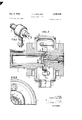
FIG. 1 is an outside perspective view of the reverse magnetron tube of the present invention,
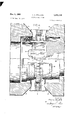
FIG. 2 is an enlarged fragmentary view partly broken away and partly in section of the structure of FIG. 1 taken along the line 22 in the direction of the arrows,
FIG. 3 is a fragmentary view partly in cross section and partly broken away of the portion of the structure of FIG. 2 taken along the line 33 in the direction of the arrows, and
FIG. 4 is an enlarged perspective view of the portion of the structure of FIG. 2 delineated by line 4-4.
Referring now to FIGS. 1, 2, and 3, character 1 represents the hollow tubular supporting body of the reverse magnetron, as of copper, to which other parts are brazed or otherwise suitably fastened to form a structure capable of being evacuated. On opposite sides of the body 1 in axial alignment there are brazed to the body 1 a tubular output waveguide assembly 2 and tuner assembly 3. Cathode lead-in insulator structure 4 extends outwardly from the main body of section 1 in quadrature with the axially aligned output Waveguide and tuner structures 2 and 3 respectively.
The term circular electric mode cavity, waveguide or wave supporting structure as used herein is defined to mean a cavity, waveguide, or wave supporting structure formed, dimensioned, and excited in such a manner as to support at its certain preselected operating frequency a certain circular electric mode, of the general form TE m, to the exclusion of other modes. A circular electric mode cavity, waveguide or wave supporting structure typically includes an outer cylindrical side wall and may or may not have an axially directed center conductor.
A circular electric mode cavity 5 is disposed centrally of the anode body 1 on the axis of the tube. In amplifier embodiments of the present invention, the circular electric mode cavity 5 is replaced by a circular electric wave supporting structure such as, for example, a hollow cylindrical pipe having an input port as well as an output port. A circumferential array of outwardly directed vanes 6 surround the circular electric mode cavity 5 and form an array of anode resonators by the spaces between adjacent vanes 6. Alternate anode resonators are electromagnetically coupled to the circular electric mode cavity 5 via an array of axially directed slots 7 communicating through the common wall between the anode resonators and the circular electric mode cavity 5. A magnetron interaction region 8 surrounds the outer tips of the vanes 6 and is defined by the space inbetween the vanes 6 and a surrounding cathode emitter ring 9.
A strong axial magnetic field as of 12,000 to 15,000 gauss for the magnetron interaction region 8 is provided by a bowl shaped magnet 11, only partially shown in FIG. 2, enveloping the anode body portion 1 and having a re-entrant internal magnetic gap extending in the axial direction through the magnetron interaction region 8 between the magnetic pole pieces 12 disposed on opposite sides of the anode vanes 6.
Tuning of the tube over its approximate 12% tuning band, centered at approximately 34 gigacycles, is obtained by means of axial translation of a combined cavity end wall and output coupling plate 13 can'ied upon the end of an axially directed and positioned rod 14 which is axially translatable via the intermediary of a captured nut 15 and bellows assembly 16, partially shown. The output coupling plate forms the subject matter of and is claimed in co-pending US. application 216,228, filed August 10, 1962, and assigned to the same assignee s the present invention.
The negative cathode potential of approximately 23 kv. is applied to the cathode emitter 9 via high voltage lead-in insulator assembly 4. The cathode 9 uses a low voltage A.C. filament heater and therefore a dual wire cathode lead-in 10 is used.
In operation, the 1r mode of the anode resonator structure adjacent the magnetron interaction region is locked to the circular electric mode cavity resonator via the intermediary of the coupling slots 7 serving to drive the resonator 5. An annular slot mode absorber 24, juxtapositioned the coupling plate end of the slots 7, suppresses the undesired slot mode. Output energy from the resonator 5 is extracted via the coupling plate 13 and transmitted to the load, not shown, via the intermediary of the circular electric mode output waveguide structure 2 and output vacuum tight wave permeable window 17.
The novel coupling slot cover feature of the present invention will now be more fully described with regard to the structure of FIG. 4. As previously explained, the circular electric mode cavity 5 is provided with a circumferential array of axially directed slots 7 communicating between the anode resonator system and the circular electric mode cavity 5. For optimum operating conditions, it is desired to attain as much coupling as possible between the circular electric mode cavity 5 and the anode resonator system.
Therefore, the axial slots 7 are made as long as possible. Typically, the circular electric mode resonator 5 is approximately /2 wavelength long in the axial direction such that the slots, at maximum length, are approximately /2 wavelength long for such a cavity designed for operation on the TE 1, 1 mode.
However, long slots 7 serve to radiate cavity energy into the cathode region causing an undesired loss of energy. This loss of energy from the circular electric mode cavity 5 reduced the efficiency of the prior art tube and originally lowered the Qs to an intolerable level.
It was found that by covering one or more of the ends of the coupling slots 7 by thin conductive metal bands 31 and 32, as of copper, respectively, that unwanted radiation from the slots is eliminated and furthermore the slot mode, an interfering mode of operation associated with the energy stored in the resonant slots, was suppressed by the lowering of the Q of the slot mode due to the presence of the conductive bands 31 and 32.
Furthermore, it was found desirable that the conductive bands 31 and 32 should not form a good conductive connection, as would be formed by brazing the bands 31 and 32 over the slots 7 but that, in a preferred embodiment, the bands 31 and 32 are loosely affixed over the ends of the slots and retained there by a mechanical lock such as by staking or peening the band 31 at 33 to the anode wall 19.
It is also preferred that the bands 31 and 32 be disposed on the vane side of the anode wall 19. However, because of the positioning of the mode absorber 24 on the vane side of the anode wall it is preferred that the slot cover 32 on that end of the anode wall 19, be disposed on the cavity side of the wall 19 so as not to excessively shield the slot mode absorber 24 from the slot fields. The slot mode absorber 24 and its support structure form the subject matter of and are claimed in copending US. application 223,499, filed September 13, 1962, now issued as US. 3,231,781 on January 25, 1966 and assigned to the same assignee as the present invention.
In a typical example used at 35 gigacycles, the anode wall 19 has a thickness of approximately 0.020", the slots are 0.005" wide and the conductive bands 31 and 32 are relatively thin, having a thickness of approximately 0.007. In a preferred embodiment, the bands 31 and 32 extend axially co-extensively with the cavity 5, slots 7, and inwardly from the ends of the slots 7 such as to leave approximately A Of a wavelength of the central portion of the slots 7 exposed and uncovered. The poor electrical contact formed at the junction between the wall 19 and the abutting slot covers 31 and 32 form a high resistance electrical junction to the slot mode currents tending to lower the Q of the slot mode and thereby suppress oscillation of the slot mode.
It is preferred that the radial spacing, if any, between the slotted portion of the wall 19 and the overlaying slot cover be less than the slot width. Otherwise the slot cover may not effectively reduce radiation. It is also preferred that the slot cover be axially coextensive with the ends of the slots by an amount greater than the slot width or thickness. Otherwise the effective electrical resistance offered to the slot mode currents by the slot cover will be reduced as a result of the shunting effect of the end of the slots.
Since many changes can be made in the above construction and many apparently widely different embodiments of this invention could be made without departing from the scope thereof, it is intended that all matter contained in the above description or shown in the accompanying drawings shall be interpreted as illustrative and not in a limiting sense.
What is claimed is:
1. Coupling apparatus for coupling an array of vane resonators to a circular electric mode wave supporting structure through a common wall member including, a circumferential array of radially directed vane resonators, a circumferential array of elongated axially directed coupling slots communicating through the common wall member between the circular electric mode wave supporting structure and the array of vane resonators, said slots having an axial length greater than a quarter wavelength at the center operating frequency of the circular electric mode structure for maximum energy exchange between the array of resonators and the circular electric wave supporting structure, said slots having an axial length substantially greater than the axial height of said vane resonators, and means forming a conductor juxtapositioned said slots on said array of resonators side of said common wall with a separation between the slotted common wall and said conductor means being less than the width of the coupling slots and covering at least one end portion of a plurality of said coupling slots by being axially co-extensive therewith over an end portion of said slots for reducing wave energy radiation from said slots.
2. In a crossed field tube apparatus, a cathode, an anode wall with a plurality of vanes extending from one side and defining a plurality of anode resonators adjacent said cathode, means defining within said anode wall a second cavity resonator, means for coupling alternate ones of said anode resonators to said second cavity resonator and including a plurality of slots communicating through said anode wall between said anode resonators and said second cavity resonator, said slots having an axial length substantially greater than the axial height of said vane resonators, means forming an electrically conductive slot cover positioned over at least one end of said slots on said anode resonator side of said anode wall with the spacing between said slotted anode wall and said conductive slot cover being less than the slot width for reducing wave energy radiation from said slots and for reducing the Q of the slot mode.
3. A reverse magnetron tube apparatus including, an evacuable body portion, an inner cavity resonator for sustaining a TE, 1 mode of oscillation and having an outer cylindrical side wall, a circumferential array of anode resonators surrounding said cylindrical outer wall and supported therefrom, means for locking the 1r mode of oscillation of said anode resonator array to said TE 1 mode of said inner cavity resonator, said locking means including a circumferential array of axially directed slots extending through said outer cavity wall member at alternate ones of said anode resonators, said slots having an axial length substantially greater than the axial height of said anode resonators at their support from said outer wall, means forming an electrically conductive slot cover positioned on said anode resonator side of said cavity wall member over at least one end of said slots and abutting said slotted portion of said wall for reducing wave energy radiation from said slots and for reducing the Q of a slot mode.
4. The apparatus according to claim 3 including, means forming a slot mode absorber positioned at one end of said slots and covering one end portion of said slots for suppression of an unwanted slot mode.
5. The apparatus according to claim 4 wherein said slot mode absorber is positioned on the vane side of said anode wall, and a second slot cover means is disposed on the opposite side of said anode wall from said slot mode absorber and is disposed axially coextensive with a portion of said slot mode absorber, and a portion of said slot mode absorber extending in the aixal direction toward the center of said slots a greater distance than said second slot cover extends toward the center of said slots, whereby said slot mode absorber is not totally shielded from the slot mode by said second slot cover means.
6. The apparatus according to claim 3, wherein said slot cover means includes a thin metallic band abutting said anode wall at the slotted portions thereof defined by said Wall portions inbetween the covered end portions of said slots, and the RF. junction formed between said slotted anode Wall member and said abutting slot cover band forming a relatively high resistance connection across said slots for reducing the Q of the slot mode.
'7. In a crossed field tube apparatus, a cathode, an anode wall with a plurality of vanes extending from one side and defining a plurality of anode resonators adjacent said cathode, means defining with said anode Wall a circular electric mode cavity resonator having axially spaced wave reflective members defining end cavity portions, means for coupling alternate ones of said anode resonators to said circular electric mode cavity and including a plurality of axially directed slots communicating through said anode Wall between said anode resonators and said circular electric mode cavity resonator, said slots having an axial length substantially greater than the axial height of said vanes at their point of connection to said anode Wall, means forming an electrically conductive slot cover positioned over said slots and being axially coextensive with an end portion of said circular electric mode cavity resonator, whereby Wave energy radiation from said circular electric mode cavity via said coupling slots into the cathode is minimized for increasing the efiiciency and stability of the crossed field tube apparatus.
8. The apparatus according to claim 7 wherein said slot cover means has an axial extent coextensive with the axial extent of said circular electric mode cavity greater than the slot width whereby the Q of a mode of oscillation associated with energy storage in the slots is reduced.
9. The apparatus according to claim 8 wherein the spacing between said slotted anode Wall and said overlaying conductive slot cover is less than the slot width for reducing the Q of the slot mode.
References Cited by the Examiner UNITED STATES PATENTS 2,408,234 9/1946 Spencer 315-39.7S X 2,426,656 9/1947 Wilbur 313326 X 2,482,495 9/1949 Laidig 315-39.75 2,815,469 12/1957 Sixsrnith 31539.77 X 2,951,182 8/1960 Feinstein 31539.61 X
HERMAN KARL SAALBACH, Primary Examiner.
GEORGE N. WESTBY, Examiner.
S. CHATMON, Assistant Examiner.
Claims (1)
1. COUPLING APPARATUS FOR COUPLING AN ARRY OF VANE RESONATORS TO A CIRCULAR ELECTRIC MODE WAVE SUPPORTING STRUCTURE THROUGH A COMMON WALL MEMBER INCLUDING, A CIRCUMFERENTIAL ARRAY OF RADIALLY DIRECTED VANE RESONATORS, A CIRCUMFERENTIAL ARRAY OF ELONGATED AXIALLY DIRECTED COUPLING SLOTS COMMUNICATING THROUGH THE COMMON WALL MEMBER BETWEEN THE CIRCULAR ELECTRIC MODE WAVE SUPPORTING STRUCTURE AND THE ARRAY OF VANE RESONATORS, SAID SLOTS HAVING AN AXIAL LENGTH GREATER THAN A QUARTER WAVELENGTH AT THE CENTER OPERATING FREQUENCY OF CIRCULAR ELECTRIC MODE STRUCTURE FOR MAXIMUM ENERGY EXCHANGE BETWEEN THE ARRAY OF RESONATORS AND THE CIRCULAR ELECTRIC WAVE SUPPORTING STRUCTURE, SAID SLOTS HAVING AN AXIAL LENGTH SUBSTANTIALLY GREATER THAN THE AXIAL HEIGHT OF SAID VANE RESONATORS, AND MEANS FORMING A CONDUCTORS JUXTAPOSITIONED SAID SLOTS ON SAID ARRAY OF RSONATORS SIDE OF SAID COMMON WALL WITH A SEPARATION BETWEEN THE SLOTTED COMMON WALL AND SAID CONDUCTOR MEANS BEING LESS THAN THE WIDTH OF THE COUPLING SLOTS AND COVERING AT LEAST ONE END PORTION OF A PLURALITY OF SAID COUPLING SLOTS BY BEING AXIALLY CO-EXTENSIVE THEREWITH OVER AND END PORTION OF SAID SLOTS FOR REDUCING WAVE ENERGY RADIATION FROM SAID SLOTS.
Priority Applications (3)
| Application Number | Priority Date | Filing Date | Title |
|---|---|---|---|
| US216227A US3290548A (en) | 1962-08-10 | 1962-08-10 | Reverse magnetron |
| GB2507166A GB1061712A (en) | 1962-08-10 | 1963-08-09 | Electron discharge tubes including coupling means between a wave-supporting structureand an array of resonators |
| JP38040875A JPS4945617B1 (en) | 1962-08-10 | 1963-08-09 |
Applications Claiming Priority (5)
| Application Number | Priority Date | Filing Date | Title |
|---|---|---|---|
| FR1372678T | |||
| US216228A US3289035A (en) | 1962-08-10 | 1962-08-10 | Reverse magnetron having means to suppress undersired modes |
| US216227A US3290548A (en) | 1962-08-10 | 1962-08-10 | Reverse magnetron |
| US219702A US3255377A (en) | 1962-08-10 | 1962-08-27 | Reverse magnetron with cathode support structure |
| US221796A US3223876A (en) | 1962-09-06 | 1962-09-06 | Cathode heater assembly for use in strong d.c. magnetic fields |
Publications (1)
| Publication Number | Publication Date |
|---|---|
| US3290548A true US3290548A (en) | 1966-12-06 |
Family
ID=27515642
Family Applications (1)
| Application Number | Title | Priority Date | Filing Date |
|---|---|---|---|
| US216227A Expired - Lifetime US3290548A (en) | 1962-08-10 | 1962-08-10 | Reverse magnetron |
Country Status (1)
| Country | Link |
|---|---|
| US (1) | US3290548A (en) |
Cited By (1)
| Publication number | Priority date | Publication date | Assignee | Title |
|---|---|---|---|---|
| US8446096B1 (en) * | 2009-10-02 | 2013-05-21 | The United States Of America As Represented By The Secretary Of The Navy | Terahertz (THz) reverse micromagnetron |
Citations (5)
| Publication number | Priority date | Publication date | Assignee | Title |
|---|---|---|---|---|
| US2408234A (en) * | 1941-11-26 | 1946-09-24 | Raytheon Mfg Co | Tunable magnetron |
| US2426656A (en) * | 1944-12-11 | 1947-09-02 | Gen Electric | High-frequency electric discharge device |
| US2482495A (en) * | 1943-11-27 | 1949-09-20 | Westinghouse Electric Corp | Magnetron |
| US2815469A (en) * | 1951-01-08 | 1957-12-03 | English Electric Valve Co Ltd | Magnetron oscillators |
| US2951182A (en) * | 1957-11-25 | 1960-08-30 | Bell Telephone Labor Inc | Magnetron |
-
1962
- 1962-08-10 US US216227A patent/US3290548A/en not_active Expired - Lifetime
Patent Citations (5)
| Publication number | Priority date | Publication date | Assignee | Title |
|---|---|---|---|---|
| US2408234A (en) * | 1941-11-26 | 1946-09-24 | Raytheon Mfg Co | Tunable magnetron |
| US2482495A (en) * | 1943-11-27 | 1949-09-20 | Westinghouse Electric Corp | Magnetron |
| US2426656A (en) * | 1944-12-11 | 1947-09-02 | Gen Electric | High-frequency electric discharge device |
| US2815469A (en) * | 1951-01-08 | 1957-12-03 | English Electric Valve Co Ltd | Magnetron oscillators |
| US2951182A (en) * | 1957-11-25 | 1960-08-30 | Bell Telephone Labor Inc | Magnetron |
Cited By (2)
| Publication number | Priority date | Publication date | Assignee | Title |
|---|---|---|---|---|
| US8446096B1 (en) * | 2009-10-02 | 2013-05-21 | The United States Of America As Represented By The Secretary Of The Navy | Terahertz (THz) reverse micromagnetron |
| US8624497B1 (en) | 2009-10-02 | 2014-01-07 | The United States Of America As Represented By The Secretary Of The Navy | Terahertz (THz) reverse micromagnetron |
Similar Documents
| Publication | Publication Date | Title |
|---|---|---|
| US3315121A (en) | Crossed-field electric discharge device | |
| US2760111A (en) | Magnetron amplifier | |
| US3346766A (en) | Microwave cold cathode magnetron with internal magnet | |
| US3432722A (en) | Electromagnetic wave generating and translating apparatus | |
| US3904919A (en) | Rotary tuner for a circular electric mode crossed field tube | |
| US3289035A (en) | Reverse magnetron having means to suppress undersired modes | |
| US3223882A (en) | Traveling wave electric discharge oscillator with directional coupling connections to a traveling wave structure wherein the number of coupling connections times the phase shift between adjacent connections equal an integral number of wavelengths | |
| US3027488A (en) | Tunable magnetrons | |
| US3290548A (en) | Reverse magnetron | |
| US6084353A (en) | Coaxial inductive output tube having an annular output cavity | |
| US3376463A (en) | Crossed field microwave tube having toroidal helical slow wave structure formed by a plurality of spaced slots | |
| US2748277A (en) | Magnetron noise generators | |
| US2747137A (en) | High frequency electrical apparatus | |
| US5537002A (en) | Frequency tunable magnetron including at least one movable backwall | |
| US2591976A (en) | Electron discharge device utilizing cavity resonators | |
| US3231781A (en) | Reverse magnetron with slot mode absorber | |
| US2597506A (en) | Ultra-short wave electron tube | |
| US2530185A (en) | Electron discharge device | |
| US2992362A (en) | High frequency crossed-field device | |
| US3379926A (en) | Coaxial magnetron having slot mode suppressing lossy material in anode resonators | |
| US3274433A (en) | Magnetron and radio frequency circuitry therefor | |
| US3483420A (en) | Klystron amplifier employing helical distributed field buncher resonators and a coupled cavity extended interaction output resonator | |
| US2595652A (en) | Coupled cavity resonator | |
| US3289023A (en) | Magnetron with helical cathode held by support, the output and mode suppression means being remote from the cathode support | |
| US2592408A (en) | Electron discharge device |