US3286133A - Meter pedestal - Google Patents
Meter pedestal Download PDFInfo
- Publication number
- US3286133A US3286133A US393581A US39358164A US3286133A US 3286133 A US3286133 A US 3286133A US 393581 A US393581 A US 393581A US 39358164 A US39358164 A US 39358164A US 3286133 A US3286133 A US 3286133A
- Authority
- US
- United States
- Prior art keywords
- panels
- enclosure
- sliding engagement
- sections
- corner
- Prior art date
- Legal status (The legal status is an assumption and is not a legal conclusion. Google has not performed a legal analysis and makes no representation as to the accuracy of the status listed.)
- Expired - Lifetime
Links
- NJPPVKZQTLUDBO-UHFFFAOYSA-N novaluron Chemical compound C1=C(Cl)C(OC(F)(F)C(OC(F)(F)F)F)=CC=C1NC(=O)NC(=O)C1=C(F)C=CC=C1F NJPPVKZQTLUDBO-UHFFFAOYSA-N 0.000 title description 4
- 239000012212 insulator Substances 0.000 description 19
- 238000009434 installation Methods 0.000 description 8
- XAGFODPZIPBFFR-UHFFFAOYSA-N aluminium Chemical compound [Al] XAGFODPZIPBFFR-UHFFFAOYSA-N 0.000 description 7
- 229910052782 aluminium Inorganic materials 0.000 description 7
- 239000004020 conductor Substances 0.000 description 7
- 238000010276 construction Methods 0.000 description 7
- 238000004891 communication Methods 0.000 description 5
- 238000001125 extrusion Methods 0.000 description 4
- 238000003780 insertion Methods 0.000 description 3
- 230000037431 insertion Effects 0.000 description 3
- 238000012423 maintenance Methods 0.000 description 2
- GRNHLFULJDXJKR-UHFFFAOYSA-N 3-(2-sulfanylethyl)-1h-quinazoline-2,4-dione Chemical compound C1=CC=C2C(=O)N(CCS)C(=O)NC2=C1 GRNHLFULJDXJKR-UHFFFAOYSA-N 0.000 description 1
- 241000726103 Atta Species 0.000 description 1
- 102000010970 Connexin Human genes 0.000 description 1
- 108050001175 Connexin Proteins 0.000 description 1
- 230000000712 assembly Effects 0.000 description 1
- 238000000429 assembly Methods 0.000 description 1
- 238000013461 design Methods 0.000 description 1
- 238000010616 electrical installation Methods 0.000 description 1
- 210000003976 gap junction Anatomy 0.000 description 1
- 238000012986 modification Methods 0.000 description 1
- 230000004048 modification Effects 0.000 description 1
- 230000007935 neutral effect Effects 0.000 description 1
- 229920000136 polysorbate Polymers 0.000 description 1
- 230000002441 reversible effect Effects 0.000 description 1
- 238000006467 substitution reaction Methods 0.000 description 1
Images


Classifications
-
- H—ELECTRICITY
- H02—GENERATION; CONVERSION OR DISTRIBUTION OF ELECTRIC POWER
- H02B—BOARDS, SUBSTATIONS OR SWITCHING ARRANGEMENTS FOR THE SUPPLY OR DISTRIBUTION OF ELECTRIC POWER
- H02B1/00—Frameworks, boards, panels, desks, casings; Details of substations or switching arrangements
- H02B1/26—Casings; Parts thereof or accessories therefor
- H02B1/50—Pedestal- or pad-mounted casings; Parts thereof or accessories therefor
Definitions
- This invention relates ⁇ to housings suitable for use with electrical equipment and particularly adapted for use with underground utility services.
- the conductors are positioned in conduit buried in the ground while the meters, breakers, terminal panels and the like zare mounted in some form of housing above the ground for ease of installation, maintenance, meter reading and the like. It is an object of the present invention to provide a new and improved housing for use in such installations.
- a further object is to provide such a housing which can be combined with similar housings to provide service to any number of customer units, to provide for the combination of electric power and telephone service, to provide electric power transformers, metering and distribution in a single structure.
- a further object is to provide such a housing in which the enclosure may be any desired height and incorporates a simple top cover for protection against the elements.
- a further object is to provide such a structure utilizing side panels and corner panels with the side panels being slidably removable providing access to the interior of the enclosure, providing for joining of additional enclosures and providing for variations in panel structure and form.
- the invention also comprises novel details of construction and novel combinations and arrangements of parts, which will more fully appear in the course of the following description.
- the drawings merely show and the description merely describes preferred embodiments of the present invention which are given by Way of illustration or example.
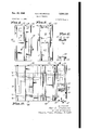
- FIG. 1 is an isometric view of a single enclosure housing incorporating the teaching of the invention
- FIG. 2 is an enlarged top view of the housing of FIG. 1 with the cover removed;
- FIG. 3 is an enlarged sectional view taken along the line 3 3 of FIG. 1;
- FIG. 4 is a side view of an alternative embodiment of the housing showing a combination of two enclosures
- FIG. 5 is a side view of another alternative form of the housing showing a combinati-on of two enclosures
- FIG. 6 is an enlarged sectional View taken along the line 6 6 of FIG. 4;
- FIG. 7 is an enlarged sectional view taken along the line 7 7 of FIG. 4;
- FIG. 8 is a sectional View taken along the line 8 8 of FIG. 7;
- FIG. 9 is an enlarged sectional view taken along the line 9 9 of FIGS. 5 and 10;
- FIG. 10 is a side View of another alternative form of the invention illustrating a plurality of enclosures with a distribution transformer in one of the enclosures;
- FIG. l1 is an enlarged sectional view taken along the line 11 11 of FIG. 10;
- FIG. 12 is Ia top view of the left portion of the structure of FIG. 10 with the cover removed;
- FIG. 13 is an enlarged view ⁇ of a portion of FIG. 12 indicated by the arrow 13;
- FIG. 14 is a .sectional View taken along the line 14 14 of FIG. 10.
- FIGS. 1, 2 and 3 illustrate the basic housing as used for metering and distribution of electric power service to four customers utilizing underground cable installations.
- An enclosure 20 may be mounted .on a base 21 and may have a removable cover 22.
- Ithe ibase 21 is a concrete pad set in the ground with one or more underground conduits 23 iixed therein, with the conduits opening into the lower end of the interior of the enclosure 20.
- the enclosure is formed of a plurality of panels which are slidably engageable with each other and which typically may be aluminum extrusions which can be cut off at any length to provide the desired height for the enclosure.
- the enclosure is formed of three diiferent panels 25, 26, 27.
- Each of the four corners of the enclosure is formed of one of the corner panels 25.
- One edge 2S of the corner panel 25 has a T- shaped section running the length of the edge.
- the other edge 29 has a channel-shaped section which will mate with the T-shaped section.
- the cross-section shapes of the panels 25, 26, 27 are shown enlarged Vin FIG. 6. Referring again to FIG.
- the :side panels 26 have T-shaped sections at each edge thereof for sliding engagement with the channel sections of the corner panels 25, permitting vertical sliding insertion and removal of the side panels 26.
- the side panels 27 have channel-shaped sections at each edge thereof for sliding engagement with the i T sections of the corner panels, permitting vertical sliding insertion and removal of the panels 27.
- the corner panels 25 incorporate vertically disposed channel-shaped sections 32, 33 on the interior surface thereof for receiving bolts with T-srhaped heads for supporting various members within the enclosure.
- a frame is provided within the enclosure for joining the corner panels together and for supporting electric circuit components within the enclosure.
- the frame may comprise aluminum angles 34 fixed to the corner panels at the channel sections 33 by bolts and nuts and aluminum angles 35 fixed in the channel sections 32 by bolts and nuts.
- 'Ihe angles 3S at the bottom of the enclosure (FIG. 3) may have openings for receiving studs 36 projecting upward from the base 21 for ixing the enclosure on the base.
- An insulator member 38 is mounted on the upper pair of angles 34 and another insulator member 39 is mounted on the intermediate pair of angles 34 (FIGS. 2 and 3).
- Three lengths of bus bar 40, 41, 42 are vertically disposed in spaced openings in the insulator members 38, 39.
- Four sets of meter jaws are mounted on the bus bars, two facing each direction, for supporting four plug-in meters.
- Conventional meter jaw units may be utilized and typically a unit comprises an insulator block carrying spaced spring-loaded jaws for receiving meter terminals, with each jaw having provision for connection to a bus bar or to a wire conductor.
- the insulator blocks of a meter jaw set are usually mounted on the neutral bus 41.
- the jaws 43 for the line side of the meter will be bolted to the respective line buses 40, 42.
- the jaws 44 for the load side of the meter will be spaced from the bus bars for connection of load conductors thereto.
- the load jaw members are positioned below the line jaw members.
- the insulator block 45 for the load unit of the lower set rests on the horizontal insulator member 39.
- the insulator block 46 for the line unit of the upper set engages the horizontal insulator member 38.
- the cover 22 is perferably flanged to overhang the top 'of the enclosure forprotection against the elements and may be held in place by conventional means as by pins 47 which engage openings in one edge of the cover and screws 48 passing through openings in the opposite edge. Conventional safety wiring and seals may be used on the screws if desired.
- the enclosure may be made any size, using the same standard components.
- the bus bars and the panels are cut .to the desired length with the assembly and installation being the same for all heights of housing. Only three panel shapes are required, the panels on all four sides are slidably removable for ease of electrical installation and maintenance.
- the bus bars 40, 41, 42 function as electrical conductors and also function as mechanical supports for the meter jaw units ⁇ and also function as a portion 4of the interior frame which makes the enclosure a rigid structure.
- the modular construction of the housing permits a number of variations, some of which will be described herein. In making underground utility service installations, it is often desirable to provide both electric power and telephone service at a single point.
- two corner panels 25 and a side panel 26 are combined to provide a second enclosure atlixed to the enclosure of FIG. 1.
- the corner panel is preferably provided with a vertical channel 52 on the exterior surface thereof for slidingly receiving the T-shaped edge of another corner panel, as seen in FIG. 6.
- An enclosure 53 is affixed to the enclosure 20 by mounting the corner panels 25 of the enclosure 53 in the channel sections 52 of corner panels of the enclosure 20.
- One or 'more aluminum angles 54 may be mounted between the 'corner panels of the enclosure 53 for fixing the corner panels in position and for carrying electric components inside the enclosure 53.
- the panel 26 is slidably removable for access to the interior of the enclosure 53.
- the side panels 26, 27 may be provided with channel sections 33 in the same manner as are the corner panels for receiving bolt heads or the like. In a conventional installation, these side panels will be installed so that the channel sections face inward.
- the side panel 27 (FIG. 6) may be removed, reversed and replaced to provide the channel sections 33 facing into the second enclosure for mounting equipment therein, illustrated as a bracket 55. This type of construction provides two completely isolated enclosures. If desired, the
- 4 panel 27 may be removed providing two enclosures with a communication passage therebetween.
- a singe cover may be provided for the housing of FIGS. 4 and 6, but it is preferred to provide a separate cover for each enclosure permitting any combination of enclosures to be produced without requiring custom-made covers.
- an upward opening channel member 57 is positioned in the upper end of the enclosure 53 in openings 58 provided in the corner panels 25 of the enclosure 53 adjacent the corner panels 25 of the enclosure 20.
- the channel member 57 preferably has a flange 59 at each end overhanging the corner panel for maintaining the channel member in position.
- the downwardly turned flange of the cover 22 is positioned in the channel member, as seen in FIGS. 7 and 8.
- the enclosure 53 has its downwardly turned flange'also positioned in the channel member.
- two or more of the standard size enclosures 20 may be joined side by side to provide any desired amount of interior space.
- the side-by-side mounting of two such enclosures 66, 67 together with a larger enclosure 68 suitable for a transformer is illustrated in FIG. l0.
- the enclosures 66, 67 are formed in the same manner as the enclosure 20 ⁇ of FIG. 1 except that the adjacent side panels l27 of the two enclosures are omitted, as shown in FIG. l1.
- a junction member 69 typically a length of aluminum extrusion having spaced parallel channel sections for receiving the T-shaped edge sections of the corner panels 25, is slidably inserted onto the adjacent edges of the two corner panel sections.
- junction member 70 is provided at the opposite corner panel sections to define a communication space between the two enclosures 66, 67.
- a channel member 71 similar to the channel member 57 of FIG. 4, may be positioned in the upper ends of the members 69. 70 for receiving the flanges of the covers 22, 73 of ythe enclosures 66, 67 respectively. Any number of the enclosures may be joined in this manner.
- the larger enclosure 68 may be formed of the same panels as the enclosure 20.
- the top view of FIG. l2 illustrates how the panels 25, 26 and 27 are assembled to provide the enclosure 68.
- the adjacent panels 27 are joined by an I section 75 which slides into the abutting channel edges, as best seen in FIG. 13.
- Pairs of corner panels 25 are joined by channel members 76 supported on brackets 77 mounted in the channels 32, 33 of the corner panels.
- a transformer 78 may be carried on the channels 76, with the transformer structure providing additional cross bracing within the enclosure.
- One y0r more horizontal langles 79 may
- a horizontal angle or bracket 80 may be used to join the three adjacent panels 27, 26, 27 and a bracket 82 may be used to join the four adjacent panels 26, 27, 27, 26.
- These slidably removable panel assemblies provide full access to the enclosure.
- the enclosure 66 is joined to the enclosure 68 in the same manner that the enclosure -67 is joined to the enclosure 66.
- a cover 84 may be attached in the same manner as the covers for the other hou-sings. In this type of installation, the high-voltage line comes in underground an up into the enclosure 68 where it is connected to the primary side of the transformer. T-he secondary side of the transformer l ⁇ is directly Wired to the bus bars of each of the meter enclosures joined to the transformer enclosure.
- Doors or other means for access may be provided in the side panels, one such construction being shown in FIGS. 9, 19 and 14.
- an adapter section 90 typically Ian aluminum extrusion
- a numher of circuit breakers 91 are mounted on a plate 92 'which in turn is sup-ported on the adapter sections 90, as best seen in FIG. 9.
- a Z-shaped mem1ber 93 is fixed to the sections 90 adjacent the upper end of the plate 9.2 and a cover -94 is supported from the member 93 by hinges.
- the cover 94 may have flanges 95 which ride in channels 96 of the sections 90 ⁇ to provide protection against the elements.
- Another Z-shaped member 97 may be iixed to the sections 90I at .the lower end of the plate 92, with Ia tab 98 projecting through an opening in the cover 94 for receiving a lock or the like.
- the space above the circuit breaker structure just described may be enclosed by .a panel 100' which is formed from a panel 26 by removal of the T-shaped edges.
- the flanges 101 of the panel 26 (FIG. 6) ride in the channels 96 of the sections 90 in the same manner as the anges 95 of the door 94.
- Clips 102 may be fixed to the lower end ⁇ of the panel 100 for engaging the member 93 to hold the panel 100 in position.
- the cover 73 holds the upper end of the panel 100.
- This circuit breaker type of construction may of course be used with one of the smaller enclosures 53 if desired. Such installation is shown in FIG. 5, Where the hinged cover and 'breaker mounting plate are mounted at the upper end Iof the structure rather than at the lower end as shown in PIG. 10.
- the particular shape and size of the enclosures are determined by the initial design of the cross section of the three panels.
- corner panels having the same horizontal cross sections and vertically disposed sliding engagement sections on both -sides thereof, and
- a rectangular enclosure adapted for mounting on a base and having a plurality of panels, including corner panels and pairs of opposing side panels,
- a rectangular enclosure adapted for mounting on a base and having a plurality of panels, including corner panels and pairs of opposing side panels,
- a first rectangular enclosure adapted for mounting on a base and having a plurality of panels, including corner panels and pairs of opposing side panels,
- corner panels having the same horizontal cross sections and vertically disposed sliding engagement sections on both sides thereof, and
- a second enclosure adapted for mounting on a base and having a pair of said corner panels joined by a side panel interengaging sliding engagement sections
- each second enclosure corner panel engaging an exterior sliding engagement section of a corresponding rst enclosure corner panel with said first and second enclosures having a common side;
- top means for covering the upper ends of said enclosures.
- a housing for a plurality of electric service meters or the like t-he combination of a irst rectangular enclosure adapted for mounting on a base and having a plurality of panels, including corner panels and pairs of opposing side panels,
- corner panels having the same horizontal cross sections and vertically disposed sliding engagement sections on both sides thereof, and
- first laterally disposed frame members within said first enclosure fixed to sliding engagement sections of said corner panels;
- a second enclosure adapted for mounting on a base and having a pair of said corner panels joined by a side panel at interengaging sliding engagement sections
- each second enclosure corner panel engaging an exterior sliding engagement section of a corresponding first enclosure corner pane1 with said first and second enclosures having a common side;
- first and second rectangular enclosures adapted for mounting side by side on a base, each having a plurality of panels, including cornerpanels and side panels, with a gap in one side, and with the gaps of said enclosures providing communication therebetween,
- a first junction member having parallel sliding engagement sections engaging the edge sliding engagement sections of a pair of parallel disposed gap defining panels of said enclosures;
- junction member having parallel sliding engagement sections engaging the edge sliding engagement sections of another pair of parallel disposed gap defining panels of said enclosures, with said junction members providing a closed passage between the interiors of said enclosures;
- top means for covering the upper ends of said enclosures.
- first and second rectangular enclosures adapted for mounting side by side on a base, each having a plurality of panels, including corner panels,V a pair of opposing side panels, and another side panel opposite a gap, with the gaps of sa-id enclosures providing communication therebetween,
- corner panels having the same horizontal cross sections and vertically disposed sliding engagement sections on the sides thereof, and
- a first junction member having parallel sliding engagement sections engaging the edge sliding engagement sections of a pair of parallel ldisposed gap defining corner panels of said enclosures;
- junction member having parallel sliding engagement sections engaging the edge sliding engagement sections of another pair of parallel disposed gap defining corner panels of said enclosure, with said junction members providing a closed passage be'- tween the interiors of said enclosures;
- first and second rectangular enclosures adapted for mounting side -by side on a base and having adjacent gaps providing communication therebetween
- each enclosure having a vertically disposed sliding engagement section adjacent each gap edge;
- gap junction means including a first member with parallel sliding engagement sections engaging the sliding engagement sections of said enclosures at one edge of the gaps and a second member with parallel sliding engagement sections engaging the sliding engagement sections of said enclosures at the opposite side of the gaps, with said junction means providing a closed passage between the interiors of said enclosures;
- top means for covering the upper ends of said enclosures.
- a rectangular enclosure adapted for mounting on a base and having a plurality of panels, including corner panels and pairs of opposing side panels,
- corner panels having the same horizontal cross sections and with the side panels of one pair having the same horizontal cross sections
- one panel Iof the other pair including means defining van opening, a coverfor said opening, and a circuit -component support plate mounted in said open- 111g;
- laterally disposed frame members wit-hin said enclosure meters or the like, the combination of:
- a first rectangular enclosure adapted for mountingon a base and having a plurality of panels, including corner panels and pairs of opposing side panels,
- corner panels having the same horizontal cross sections and vertically disposed sliding engagement sections on both sides thereof, and
- a second rectangular enclosure adapted for mounting on a base and having a pair of said corner panels joined by a side panel at interengaging sliding engagement sections
- each second enclosure corner panel engaging an exterior sliding engagement section of a corresponding rst enclosure corner panel with said rst and second enclosures having a common side
- said second enclosure side panel including means defining an opening, a cover for said opening, and a circuit component support plate mounted in said opening;
- top means for covering the upper ends of said enclosures.
- a rectangular enclosure adapted for mounting on a base and having a plurality of panels, including corner panels and pairs of opposing side panels,
- a rectangular enclosure adapted for mounting on a base and having a plurality of panels, including corner panels and pairs of opposing side panels,
- corner panels having uniform horizontal cross sections and vertically disposed sliding engagement channels on the inner sides thereof, and
- a rst rectangular enclosure adapted for mounting on a base and having a plurality of panels, including corner panels and pairs of opposing side panels,
- corner panels having the same horizontal cross sections and vertically disposed sliding engagement sections on the exterior thereof, and
- a second enclosure adapted for mounting on a base and having a pair of said corner panels joined by a s ide panel at interengaging sliding engagement sectlons,
- each second enclosure corner panel engaging an exterior sliding engagement section of a corresponding rst enclosure corner panel wth said rst and second enclosures having a commonA side;
- top means for covering the upper ends of said enclosures.
Landscapes
- Engineering & Computer Science (AREA)
- Power Engineering (AREA)
- Patch Boards (AREA)
Description
Claims (1)
Priority Applications (1)
| Application Number | Priority Date | Filing Date | Title |
|---|---|---|---|
| US393581A US3286133A (en) | 1964-09-01 | 1964-09-01 | Meter pedestal |
Applications Claiming Priority (1)
| Application Number | Priority Date | Filing Date | Title |
|---|---|---|---|
| US393581A US3286133A (en) | 1964-09-01 | 1964-09-01 | Meter pedestal |
Publications (1)
| Publication Number | Publication Date |
|---|---|
| US3286133A true US3286133A (en) | 1966-11-15 |
Family
ID=23555327
Family Applications (1)
| Application Number | Title | Priority Date | Filing Date |
|---|---|---|---|
| US393581A Expired - Lifetime US3286133A (en) | 1964-09-01 | 1964-09-01 | Meter pedestal |
Country Status (1)
| Country | Link |
|---|---|
| US (1) | US3286133A (en) |
Cited By (23)
| Publication number | Priority date | Publication date | Assignee | Title |
|---|---|---|---|---|
| US3471029A (en) * | 1967-08-29 | 1969-10-07 | Spedcor Electronics Inc | Instrument mounting system |
| US3628097A (en) * | 1969-11-24 | 1971-12-14 | Murray Mfg Corp | Multiple-position meter socket |
| US3751717A (en) * | 1971-07-01 | 1973-08-07 | Gordon Eng Co | Bipolar floating input, particularly for digital panel meters |
| US3779177A (en) * | 1970-03-31 | 1973-12-18 | E Gigante | Modular furniture |
| US3783343A (en) * | 1972-04-27 | 1974-01-01 | C Byland | Container in which a watthour meter and a meter socket are enclosably mountable and for readably displaying the watthour meter |
| US3788241A (en) * | 1972-04-14 | 1974-01-29 | F Ravreby | Modular shoe rack |
| US3832605A (en) * | 1973-05-01 | 1974-08-27 | Westinghouse Electric Corp | Prefabricated housing for electrical switchgear with external housing wall attachment means |
| US3872234A (en) * | 1974-02-11 | 1975-03-18 | Roart Plastics Inc | Electrical cable pedestal structure |
| US4041358A (en) * | 1975-07-23 | 1977-08-09 | Sola Basic Industries, Inc. | Meter module assembly for a meter panel |
| US4133021A (en) * | 1977-07-25 | 1979-01-02 | King Harold M | Multiple utility pedestal |
| US4213111A (en) * | 1978-08-28 | 1980-07-15 | Thermodynamics Corporation | Ground level transformer unit |
| USRE31134E (en) * | 1978-08-28 | 1983-01-25 | Thermodynamics Corporation | Ground level transformer unit |
| US4435027A (en) | 1981-03-25 | 1984-03-06 | Edson Tool & Manufacturing Co., Inc. | Self-locking hinged door cabinet and latch for the same |
| EP0086198A4 (en) * | 1981-05-12 | 1985-04-24 | Common Sense Products Pty Ltd | Improvements in or relating to construction of service units. |
| EP0252195A3 (en) * | 1986-07-07 | 1989-01-25 | Gianfranco Guerra | Composable system for column deliverers of electrical energy |
| GR880100700A (en) * | 1988-10-17 | 1990-11-29 | Gian Franco Guerra | Composable system of column deliverers of electrical energy |
| EP0402621B1 (en) * | 1989-05-24 | 1993-11-24 | Kreuzer GmbH + Co. OHG | Support for apparatus |
| US5379972A (en) * | 1992-12-01 | 1995-01-10 | Legrand | Equipment support adapted to be attached to the body of trunking with inwardly facing lips |
| EP0849850A1 (en) * | 1996-12-20 | 1998-06-24 | KRONE Aktiengesellschaft | Outdoor cabinet for telecommunication devices and method for support of outdoor cabinets |
| US6008452A (en) * | 1998-04-23 | 1999-12-28 | Armin Thermodynamics | Safety lock for a pedestal cover |
| US20040069345A1 (en) * | 2002-07-29 | 2004-04-15 | Doan Duc T. | Water supply system for multiple dwelling units |
| US20040099001A1 (en) * | 2002-05-24 | 2004-05-27 | Wendt Michael E. | Base pan and cabinet for an air conditioner |
| USD555116S1 (en) * | 2006-10-06 | 2007-11-13 | Pencell Plastics, Inc. | Protective enclosure apparatus temporarily attachable to a utility pole base |
Citations (2)
| Publication number | Priority date | Publication date | Assignee | Title |
|---|---|---|---|---|
| US1196788A (en) * | 1912-01-03 | 1916-09-05 | Siemens Schuckertwerke Gmbh | Panel-board. |
| US3036244A (en) * | 1960-01-08 | 1962-05-22 | Basic Products Corp | Meter troughs |
-
1964
- 1964-09-01 US US393581A patent/US3286133A/en not_active Expired - Lifetime
Patent Citations (2)
| Publication number | Priority date | Publication date | Assignee | Title |
|---|---|---|---|---|
| US1196788A (en) * | 1912-01-03 | 1916-09-05 | Siemens Schuckertwerke Gmbh | Panel-board. |
| US3036244A (en) * | 1960-01-08 | 1962-05-22 | Basic Products Corp | Meter troughs |
Cited By (28)
| Publication number | Priority date | Publication date | Assignee | Title |
|---|---|---|---|---|
| US3471029A (en) * | 1967-08-29 | 1969-10-07 | Spedcor Electronics Inc | Instrument mounting system |
| US3628097A (en) * | 1969-11-24 | 1971-12-14 | Murray Mfg Corp | Multiple-position meter socket |
| US3779177A (en) * | 1970-03-31 | 1973-12-18 | E Gigante | Modular furniture |
| US3751717A (en) * | 1971-07-01 | 1973-08-07 | Gordon Eng Co | Bipolar floating input, particularly for digital panel meters |
| US3788241A (en) * | 1972-04-14 | 1974-01-29 | F Ravreby | Modular shoe rack |
| US3783343A (en) * | 1972-04-27 | 1974-01-01 | C Byland | Container in which a watthour meter and a meter socket are enclosably mountable and for readably displaying the watthour meter |
| US3832605A (en) * | 1973-05-01 | 1974-08-27 | Westinghouse Electric Corp | Prefabricated housing for electrical switchgear with external housing wall attachment means |
| US3872234A (en) * | 1974-02-11 | 1975-03-18 | Roart Plastics Inc | Electrical cable pedestal structure |
| US4041358A (en) * | 1975-07-23 | 1977-08-09 | Sola Basic Industries, Inc. | Meter module assembly for a meter panel |
| US4133021A (en) * | 1977-07-25 | 1979-01-02 | King Harold M | Multiple utility pedestal |
| US4213111A (en) * | 1978-08-28 | 1980-07-15 | Thermodynamics Corporation | Ground level transformer unit |
| USRE31134E (en) * | 1978-08-28 | 1983-01-25 | Thermodynamics Corporation | Ground level transformer unit |
| US4435027A (en) | 1981-03-25 | 1984-03-06 | Edson Tool & Manufacturing Co., Inc. | Self-locking hinged door cabinet and latch for the same |
| EP0086198A4 (en) * | 1981-05-12 | 1985-04-24 | Common Sense Products Pty Ltd | Improvements in or relating to construction of service units. |
| EP0252195A3 (en) * | 1986-07-07 | 1989-01-25 | Gianfranco Guerra | Composable system for column deliverers of electrical energy |
| GR880100700A (en) * | 1988-10-17 | 1990-11-29 | Gian Franco Guerra | Composable system of column deliverers of electrical energy |
| EP0402621B1 (en) * | 1989-05-24 | 1993-11-24 | Kreuzer GmbH + Co. OHG | Support for apparatus |
| US5379972A (en) * | 1992-12-01 | 1995-01-10 | Legrand | Equipment support adapted to be attached to the body of trunking with inwardly facing lips |
| AU666982B2 (en) * | 1992-12-01 | 1996-02-29 | Legrand | Equipment support adapted to be attached to the body of trunking with inwardly facing lips |
| AU736804B2 (en) * | 1996-12-20 | 2001-08-02 | Adc Gmbh | Outdoor housing for accommodating telecommunications devices and method for supporting outdoor housings |
| EP0849850A1 (en) * | 1996-12-20 | 1998-06-24 | KRONE Aktiengesellschaft | Outdoor cabinet for telecommunication devices and method for support of outdoor cabinets |
| RU2142186C1 (en) * | 1996-12-20 | 1999-11-27 | Кроне Акциенгезелльшафт | Housing for outdoor installation of telecommunication equipment and method for its adaptation to outdoor conditions |
| US6008452A (en) * | 1998-04-23 | 1999-12-28 | Armin Thermodynamics | Safety lock for a pedestal cover |
| US20040099001A1 (en) * | 2002-05-24 | 2004-05-27 | Wendt Michael E. | Base pan and cabinet for an air conditioner |
| US6912766B2 (en) * | 2002-05-24 | 2005-07-05 | American Standard International Inc. | Base pan and cabinet for an air conditioner |
| US20040069345A1 (en) * | 2002-07-29 | 2004-04-15 | Doan Duc T. | Water supply system for multiple dwelling units |
| US6860286B2 (en) * | 2002-07-29 | 2005-03-01 | Duc T. Doan | Water supply system for multiple dwelling units |
| USD555116S1 (en) * | 2006-10-06 | 2007-11-13 | Pencell Plastics, Inc. | Protective enclosure apparatus temporarily attachable to a utility pole base |
Similar Documents
| Publication | Publication Date | Title |
|---|---|---|
| US3286133A (en) | Meter pedestal | |
| US3906295A (en) | Service pedestal for electrical control means including a meter | |
| US3691288A (en) | Electrical power outlet for trailer camp sites and the like | |
| EP1237245A1 (en) | Remote distribution cabinet | |
| US2319415A (en) | Electrical control apparatus | |
| JPH0241243B2 (en) | ||
| KR100540202B1 (en) | Modular Low Voltage Switchgear | |
| US5295041A (en) | Modular construction distribution switchboard system cubicles with draw-out and fixed apparatus mounting flexibility | |
| US4199655A (en) | Circuit breaker with insulated horizontal bus bars | |
| US3469149A (en) | Insulated bus bar assembly for an electrical enclosure | |
| GB1208046A (en) | A modular system for laying electric cables between a number of electric equipments | |
| US3321672A (en) | Control center housing structure | |
| KR100540204B1 (en) | Module Assembled Low Pressure Power Unit (MCC) | |
| US2999190A (en) | Switchboard | |
| US10826281B2 (en) | Ground bus subassemblies, power distribution subassemblies, and assembly methods | |
| US3116360A (en) | Switch gear housing wall with wireway | |
| US2997629A (en) | Switchboard | |
| JPH0613535Y2 (en) | Low voltage distribution equipment | |
| US3364394A (en) | Power factor correction apparatus | |
| DE102014114938B4 (en) | Meter location with a mounting device for additional meter devices | |
| JPH07123536A (en) | Gas insulated cubicle | |
| NL8902799A (en) | METAL COATED, MODULAR MID-VOLTAGE DISTRIBUTION SYSTEM. | |
| JPH0156606B2 (en) | ||
| KR200395579Y1 (en) | Assembly typed busbar connector for low-voltage distributing board | |
| JP2876932B2 (en) | Complex type substation equipment |
Legal Events
| Date | Code | Title | Description |
|---|---|---|---|
| AS | Assignment |
Owner name: COMMANDER ELECTRICAL EQUIPMENT, INC., 950 WARDEN A Free format text: ASSIGNMENT OF ASSIGNORS INTEREST.;ASSIGNOR:GTE PRODUCTS CORPORATION;REEL/FRAME:004202/0427 Effective date: 19831130 Owner name: COMMANDER ELECTRICAL EQUIPMENT, INC., 950 WARDEN A Free format text: ASSIGNMENT OF ASSIGNORS INTEREST.;ASSIGNOR:GTE PRODUCTS CORPORATION;REEL/FRAME:004213/0332 Effective date: 19831130 Owner name: COMMANDER ELECTRICAL EQUIPMENT, INC., CANADA Free format text: ASSIGNMENT OF ASSIGNORS INTEREST;ASSIGNOR:GTE PRODUCTS CORPORATION;REEL/FRAME:004202/0427 Effective date: 19831130 Owner name: COMMANDER ELECTRICAL EQUIPMENT, INC., CANADA Free format text: ASSIGNMENT OF ASSIGNORS INTEREST;ASSIGNOR:GTE PRODUCTS CORPORATION;REEL/FRAME:004213/0332 Effective date: 19831130 |