US3281969A - Satellite orbital monitor - Google Patents
Satellite orbital monitor Download PDFInfo
- Publication number
- US3281969A US3281969A US502725A US50272565A US3281969A US 3281969 A US3281969 A US 3281969A US 502725 A US502725 A US 502725A US 50272565 A US50272565 A US 50272565A US 3281969 A US3281969 A US 3281969A
- Authority
- US
- United States
- Prior art keywords
- satellite
- globe
- earth
- ring
- inner sphere
- Prior art date
- Legal status (The legal status is an assumption and is not a legal conclusion. Google has not performed a legal analysis and makes no representation as to the accuracy of the status listed.)
- Expired - Lifetime
Links
- 230000000007 visual effect Effects 0.000 claims description 6
- 230000033001 locomotion Effects 0.000 description 19
- 210000004279 orbit Anatomy 0.000 description 12
- 230000001360 synchronised effect Effects 0.000 description 5
- 230000007246 mechanism Effects 0.000 description 4
- 238000011160 research Methods 0.000 description 4
- 230000002441 reversible effect Effects 0.000 description 3
- 230000000694 effects Effects 0.000 description 2
- 238000004088 simulation Methods 0.000 description 2
- 240000004760 Pimpinella anisum Species 0.000 description 1
- 230000009471 action Effects 0.000 description 1
- 230000004075 alteration Effects 0.000 description 1
- 230000004397 blinking Effects 0.000 description 1
- 210000004556 brain Anatomy 0.000 description 1
- 238000010586 diagram Methods 0.000 description 1
- 238000000034 method Methods 0.000 description 1
- 238000012986 modification Methods 0.000 description 1
- 230000004048 modification Effects 0.000 description 1
- 238000012544 monitoring process Methods 0.000 description 1
- 230000000737 periodic effect Effects 0.000 description 1
- 230000009467 reduction Effects 0.000 description 1
- 230000001932 seasonal effect Effects 0.000 description 1
- 238000006467 substitution reaction Methods 0.000 description 1
- 238000012360 testing method Methods 0.000 description 1
Images
Classifications
-
- G—PHYSICS
- G09—EDUCATION; CRYPTOGRAPHY; DISPLAY; ADVERTISING; SEALS
- G09B—EDUCATIONAL OR DEMONSTRATION APPLIANCES; APPLIANCES FOR TEACHING, OR COMMUNICATING WITH, THE BLIND, DEAF OR MUTE; MODELS; PLANETARIA; GLOBES; MAPS; DIAGRAMS
- G09B27/00—Planetaria; Globes
- G09B27/02—Tellurions; Orreries
-
- B—PERFORMING OPERATIONS; TRANSPORTING
- B64—AIRCRAFT; AVIATION; COSMONAUTICS
- B64G—COSMONAUTICS; VEHICLES OR EQUIPMENT THEREFOR
- B64G7/00—Simulating cosmonautic conditions, e.g. for conditioning crews
Definitions
- This invention relate-s to a means for monitoring and displaying on a reduced scale, the motion of an object as it moves with ⁇ respect to the earth. More particularly, the invention Iis concerned with providing laboratory apparatus which is capable of visually simulating the relationships between the earth land the motions of moving bjects, such as artificial satellites, especially with respect to night and day as they occur on earth.
- Another object of the invention is to present a visual indica-tion of the satellite in its proper relationship to day and night as it occurs on earth. rThis is accomplished by providing apparatus for simulating sunlight and darkness during the passage of time.
- a further object of the present invention is to provide means for simulating the time for sequential occurrence of a particular satellite-earth relationship by varying the speed of the mov-ing elements of the apparatus. This feature allows visual observations of the corresponding positions of the satellite and the earth as they will occur in the future and also allows for the return of the apparatus to synchronism with the events as they occur in real time in outer space.
- Stil-l another object of the invention is to eliminate the need for constantly plotting on charts or using lengthy tables in order to determine the instantaneous position of the satellite as -it orbits the earth. This feature is particularly useful when it is necessary or desirable to determine whether the satellite is in the daylight or night phase.
- a still further object of the invention is to provide a satellite monitor which can be adapted by adjustment or inclination to simulate the periodic revolution of the satellite around the earth regardless of the dlrection and time interval of each orbit.
- Still another object of the invention is to provide apparatus which shows the real time at Various check points on earth as related to the satellite in orbit, thereby permitting the simple Aand accurate determination of the exact time at which the .satellite will pass over any of the particular check points.
- This feature when used in con junction with ⁇ the day or night inner globe, will give a precise indication of the time and place that the satellite will be visible from earth.
- FIG. l is a block diagram illustrating the system for controlling the movement of the various elements of the invention and diagrammatic representation of the earth and satellite relationship;
- FIG. 2 is a detail view in perspective of the satellite ring drive mechanism
- FIG. 3 is a view in partial section showing the day and night'inner glo-be with the adjusting means for seasonal compensation; v
- FIG. 4 is a sectional view along the line 4-4 ⁇ of FIG. l showing the support arrangement for portions of the satellite ring; andy FIG. 5 is an enlarged View -in section showing the details of the drive mechanism for rotating the geographical globe and the adjusting means for tilting the inner sphere.
- the invention includes a transparent globe 13 representing the earth with the land masses depicted thereon.
- a vertically oriented hollow shaft 1-5 is attached at the south polar region of the earth globe 13 ⁇ and is arranged to provide rotation along the polar anis by driving the sprocket 16. Under normal operating conditions the earth globe 13 rotates once every twenty-four hours.
- the transparent geographical globe 13 is an inner sphere 17 painted half white to simulate the area of the earth on which the :sun .is shining and half black to simulate the darkened areas of the earth.
- the inner sphere 17 is adapted to be .adjusted to compensa-te for the seasons of the year by rotating the handle 1S which turns the shaft 19 and the gear 21 attached thereto causing the gear 23 to rotate the shaft 25 a corresponding amount thereby tilting the inner sphere 17 with respect to the transparent globe ⁇ 13.
- a slot 26 which is dimensioned wider than the diameter of shaft 19 is provided in the lower portion of the inner sphere 17 allowing ⁇ a 23 tilt in either direction from vertical. Since the glo-be 13 is rotating once every twentyfour hours, the condition of light or darkness can be visually determined for any point on earth by simply observing the color of the inner sphere 17 under the particular point on the transparent globe 13.
- a revolving satellite ring 27 having a spot 28 represents the position of the satellite as it orbits around the earth.
- the satellite ring 2.7 is driven by the drive rollers 29 which provides rotation about the earth of the ring 27 at a speed equal to the' Spee/.i of the satellite.
- a corresponding pair of guide rollers 31 are provided for the purpose of guiding the satellite ring 27 in its proper path *and retaining frictional pressure aga-inst the drive rollers 29 to prevent slippage.
- the drive mechanism for the satellite orbital monitor includes two electric motors.
- the first is a constant speed synchronous motor 33 which serves to provide the power for driving the various elements at their corresponding relative speeds which are comparable to the actual speeds of the earth rotation and satellite orbit.
- a variable speed reversible motor 35 is provided with suitable controls for varying the speed in either rotational direction and is connected through a diiferental 37 to the driven elements.
- the constant speed motor 33 is likewise connected to the differential 37 and, with both motors operating simultaneously, the overall effect is to add or subtract the speed of the variable motor 35 to or from the speed of the synchronous motor 33, thereby providing a means for speeding up and. reversing the occurrence of various relative positions'of the satellite with respect to the earth.
- the brake 39 between the variable speed motor 35 and the differential 37 so that the connecting shaft will not rotate during prolonged periods of constant speed operation. It is also desirable to accomplish some speed reduction between the constant speed motor 33 and the differential 37. Accordingly, the gearing 41 is introduced between these elements to obtain the desired speed ratio.
- the motion is then transmitted to two separate drive elements, namely, the variable speed drive 43 and the gear train 45 to obtain two distinct motions.
- the first motion involves the rotation of the earth globe 13 about its polar axis. This is yaccomplished by transmitting the motion from the gear train 45 through the world globe drive 47 to the vertically oriented hollow shaft 15. Under normal operating conditions the earth globe 13 revolves once every twentyfour hours in imitation of the earths rotation and is driven by the synchronous motor 33 only.
- a series of time clocks 49 are energized by the time clock drive 51 which in turn receives its motion from the gear train 45. These clocks 49 can be set to represent the actual time of day at various points on the ea-rths surface. Once set, the clocks 49 will maintain their respective time with relation to the earths rotation as it is speeded up, slowed down or reversed because the gear train 45 which provides the motion isl common to both the earth globe 13 and the clocks 49. l
- variable sped drive 43 which receives its motion from the differential 37, provides a second motion for revolving the satellite ring 27 around the earth globe 13. This is accomplished by transmitting motion through the orbit rin-g drive 53 to the drive rollers 29 by means of a flexible -cable 54 (shown in FIG. 2).
- a support arm 55 having a ball bearing 56 operably disposed at its outer limit operates to maintain the outer portions of the satellite ring 27 in orbital alignment.
- the motion of the satellite ring 27, as it revolves around the earth, operates to s-imulate the action of a satellite in orbit when the spot 28 is considered to represent the satellite.
- the angle of the satellite ring 27 can be varied with respect to the equator line as shown on the earth -globe 13 from a zero degree angle concentric with the equator and in the same planeto an angle of seventy degrees with respect to the equator line. This Vis accomplished by sliding the support block 57 along the arcuate orbital ring support member 59 and permits the simulation of the paths of all satellites normally used for research with the exception of those in near polar orbit.
- variable speed drive 43 is useful to vary the rotational speed thereof in a controlled manner from one rotation in sixty minutes to one rotation in one hund-red eight minutes and may be maintained at l bination with the flight simulator and an essential part of this invention, there isl an inner sphere 17 disposed within the transparent earth globe 13.
- the inner sphere 17 comprises two hemispheres joined together, one of which is white in color and the other being black, the jo-ining line being in a slightly inclined vertical plane.4
- the angle of inclination of the' black and white hemispheres can be changed to simulate the effect of the sun in producing simulated conditions of day and night for different seasons of the year at different points on the earths surface'.
- the spot 28 which represents the satellite can be made to light intermittently and thereby si-mulate the blinking lights with which some satellites are equipped.
- a current carrying brush in contact with a metallized portion of the satellite ring 27 is one means for energizing a small electric bulb located at the spot 29 and accomplishing the desired result.
- the earth globe 13 turning on the shaft 15 rotates one revolution in twenty-four hours.
- the satellite ring 27 is set at the proper angle with respect to the earth -globe 13 by sliding the support block 57 on the arcuate orbital -ring support member 59 to the desired angular setting. This procedure permits the simulation of the satellite as Vit orb-its the earth in its true orbital path,
- satellite ring 27 is then set in motion to travel around the rotating earth vglobe 13 at a speed proportional to that of the satellite which is being monitored so that the time interval of each revolution ofthe ring 274 around the globe 13 is the salme as that of the actual satellite.
- the spot 28 is positioned on the ring at a point 'which corresponds to the position of the actual satellite with respect to the earth itself.
- the inner sphere 17 is tilted to the proper angle to correspond to the season of the year during which the test is taking place by adjusting the handwheel 18.
- This latter feature is extremely important because if the position of the satellite is known when the earth is in a twilight or early dawn phase, visual observations of the actual satellite can be made from the earth. This is useful for photographic recordings and time synchronizing operations, particularly when the satellite is of the type equipped with intermittently flashing lights.
- variable speed motor 35 can be activated and its motion integrated with that of the constant speed motor 33 thereby speed-V revolution per twenty-four hours. In this manner, it can be quickly and easily determined that the satellite will bc visible from some particular place on earth at the predetermined future time. No lengthy computations, with the accompanying chance of error, is involved in making the determinations.
- Each of the clocks 49 being synchronized with the earth globe 13, will automatically indicate the proper future time at the several corresponding points on earth and the inner sphere 17 will indicate the day or night phase.
- the motor 35 may be reversed and the mechanism returned to its normal operation so that the several elements are in synchronism with the movement of theactual satellite as it orbits the earth.
- the transparent lgeographical earth globe 13 is substantially spherical and rotates on a vertical axis while it is well known that, as a matter of fact, the earth itself does not rotate on a vertical axis, with respect to the sun in our solar system.
- this departure from reality is ⁇ unimportant because Awe are primarily concerned with 5 the relationship of the satellite with the earth itself. Further, the tilting feature of the inner sphere represents the suns relationship tothe earth.
- a satellite orbital monitor for simulating the orbit of a planetary satellite for visual presentation, the combination of a rotatable geographical earth globe having a polar axis, rst motive means operatively connected to said globe for rotation on said polar axis, a tiltable nonrotating inner sphere disposed concentrically within said globe, means for tilting said inner sphere such that a circumferential line therearound indicates the areas on earth which are in the twilight zone at specific times of day for a particular season of the year, a satellite ring having a simulated satellite thereon concentrically surrounding said globe and rotatable therearound, an elongate arcuate member substantially conforming to the curvature of said globe and lixedly atached to extend outwardly and upwardly from the lower axis terminal thereof, said satellite ring being slidable along said arcuate member for adjusting the angle of rotation of said satellite ring, second motive means operatively connected to said satellite ring for rotating said ring around said globe
- the satellite ring having the simulated satellite thereon includes means for causing said simulated satellite to blink at predetermined time intervals in synchronism withl an actual orbiting satellite, thereby providing precise world-wide instantaneous xing of the location of Va planetary satellite relative to a point on earth.
Landscapes
- Engineering & Computer Science (AREA)
- Physics & Mathematics (AREA)
- General Physics & Mathematics (AREA)
- Astronomy & Astrophysics (AREA)
- Business, Economics & Management (AREA)
- Educational Administration (AREA)
- Educational Technology (AREA)
- Theoretical Computer Science (AREA)
- Remote Sensing (AREA)
- Aviation & Aerospace Engineering (AREA)
- Instructional Devices (AREA)
Description
NOV- 1, 1966 R. w EBACHER ETAL SATELLITE ORBITAL MONITOR Filed OCl'.. 22, 1965 3 Sheets-Sheet l Nov, l, 1966 Filed Oct. 22, 1965 R. W. EBACHER ETAL SATELLITE ORBITAL MONITOR 5 Sheets-Sheet 2 Nov. 1, 1966 Filed Oct. 22, 1965 R. w. EBACHER ETAL 3,281,969
SATELLITE ORBITAL MONITOR 3 Sheets-Sheet 5 United States Patent O America as represented by the Secretary of the Air Force Filed Oct. 22, 1965, Ser. No. 502,725 2 Claims. (Cl. l5-46) This is a continuation-in part of `application Serial No. 328,765, filed December 6, 19613, now abandoned.
The invention described herein may be manufactured by or for thev United States Government for governmental purposes without payment to us of any royalty thereon.
This invention relate-s to a means for monitoring and displaying on a reduced scale, the motion of an object as it moves with` respect to the earth. More particularly, the invention Iis concerned with providing laboratory apparatus which is capable of visually simulating the relationships between the earth land the motions of moving bjects, such as artificial satellites, especially with respect to night and day as they occur on earth.
In the use of artificial satellites for scientific research, such as in geodesy, communications research, and in rnany other fields, it is necessary to coordinate the activitiesof research groups located `a-t widely distributed positions on the earths surface ba-sed on the position of the satellite at any particular instant. This can be accomplished by computers, l.so-called electronic brains, which produce lengthy tabulations of data for interpretation and plotting by scientific personnel. However, it is extremely difficult to visualize the phenomenon which these data represent because of the constantly changing relative positions of both the satellite and the earth which determines, among other things, whether the .satellite is passing through daylight or darkness as it circles the earth. is very important in the visual observation of orbiting satellites because, generally speaking, the satellite can best be seen during the twilight `and early dawn periods.
Accordingly, it is an object of .the present invention to provide a` three dimensional representation of the position which a satellite in orbit will assume with respect to the earth at any given instant.
Another object of the invention is to present a visual indica-tion of the satellite in its proper relationship to day and night as it occurs on earth. rThis is accomplished by providing apparatus for simulating sunlight and darkness during the passage of time.
A further object of the present invention is to provide means for simulating the time for sequential occurrence of a particular satellite-earth relationship by varying the speed of the mov-ing elements of the apparatus. This feature allows visual observations of the corresponding positions of the satellite and the earth as they will occur in the future and also allows for the return of the apparatus to synchronism with the events as they occur in real time in outer space.
Stil-l another object of the invention is to eliminate the need for constantly plotting on charts or using lengthy tables in order to determine the instantaneous position of the satellite as -it orbits the earth. This feature is particularly useful when it is necessary or desirable to determine whether the satellite is in the daylight or night phase.
A still further object of the invention is to provide a satellite monitor which can be adapted by adjustment or inclination to simulate the periodic revolution of the satellite around the earth regardless of the dlrection and time interval of each orbit.
fflttifl Patented Nov. l, i966 ICC Still another object of the invention is to provide apparatus which shows the real time at Various check points on earth as related to the satellite in orbit, thereby permitting the simple Aand accurate determination of the exact time at which the .satellite will pass over any of the particular check points. This feature, when used in con junction with `the day or night inner globe, will give a precise indication of the time and place that the satellite will be visible from earth.
These and other objects, features, and advantages will become more apparent from the following description taken in conjunction with the accompanying drawings wherein:
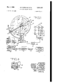
FIG. l is a block diagram illustrating the system for controlling the movement of the various elements of the invention and diagrammatic representation of the earth and satellite relationship;
FIG. 2 is a detail view in perspective of the satellite ring drive mechanism;
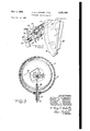
FIG. 3 is a view in partial section showing the day and night'inner glo-be with the adjusting means for seasonal compensation; v
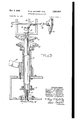
FIG. 4 is a sectional view along the line 4-4` of FIG. l showing the support arrangement for portions of the satellite ring; andy FIG. 5 is an enlarged View -in section showing the details of the drive mechanism for rotating the geographical globe and the adjusting means for tilting the inner sphere.
Referring now to the drawings in which like reference characters are used to refer to like parts throughout the specifica-tion, the invention includes a transparent globe 13 representing the earth with the land masses depicted thereon. A vertically oriented hollow shaft 1-5 is attached at the south polar region of the earth globe 13` and is arranged to provide rotation along the polar anis by driving the sprocket 16. Under normal operating conditions the earth globe 13 rotates once every twenty-four hours. Ius-ide the transparent geographical globe 13 is an inner sphere 17 painted half white to simulate the area of the earth on which the :sun .is shining and half black to simulate the darkened areas of the earth. The inner sphere 17 is adapted to be .adjusted to compensa-te for the seasons of the year by rotating the handle 1S which turns the shaft 19 and the gear 21 attached thereto causing the gear 23 to rotate the shaft 25 a corresponding amount thereby tilting the inner sphere 17 with respect to the transparent globe` 13. A slot 26 which is dimensioned wider than the diameter of shaft 19 is provided in the lower portion of the inner sphere 17 allowing `a 23 tilt in either direction from vertical. Since the glo-be 13 is rotating once every twentyfour hours, the condition of light or darkness can be visually determined for any point on earth by simply observing the color of the inner sphere 17 under the particular point on the transparent globe 13.
A revolving satellite ring 27 having a spot 28 represents the position of the satellite as it orbits around the earth. The satellite ring 2.7 is driven by the drive rollers 29 which provides rotation about the earth of the ring 27 at a speed equal to the' Spee/.i of the satellite. A corresponding pair of guide rollers 31 are provided for the purpose of guiding the satellite ring 27 in its proper path *and retaining frictional pressure aga-inst the drive rollers 29 to prevent slippage.
The drive mechanism for the satellite orbital monitor includes two electric motors. The first is a constant speed synchronous motor 33 which serves to provide the power for driving the various elements at their corresponding relative speeds which are comparable to the actual speeds of the earth rotation and satellite orbit. A variable speed reversible motor 35 is provided with suitable controls for varying the speed in either rotational direction and is connected through a diiferental 37 to the driven elements. The constant speed motor 33 is likewise connected to the differential 37 and, with both motors operating simultaneously, the overall effect is to add or subtract the speed of the variable motor 35 to or from the speed of the synchronous motor 33, thereby providing a means for speeding up and. reversing the occurrence of various relative positions'of the satellite with respect to the earth.
As a practical matter, it is desirable to introduce the brake 39 between the variable speed motor 35 and the differential 37 so that the connecting shaft will not rotate during prolonged periods of constant speed operation. It is also desirable to accomplish some speed reduction between the constant speed motor 33 and the differential 37. Accordingly, the gearing 41 is introduced between these elements to obtain the desired speed ratio.
Having obtained an integrated speed from the motors 33 and 35 through the differential 37, the motion is then transmitted to two separate drive elements, namely, the variable speed drive 43 and the gear train 45 to obtain two distinct motions. The first motion involves the rotation of the earth globe 13 about its polar axis. This is yaccomplished by transmitting the motion from the gear train 45 through the world globe drive 47 to the vertically oriented hollow shaft 15. Under normal operating conditions the earth globe 13 revolves once every twentyfour hours in imitation of the earths rotation and is driven by the synchronous motor 33 only. If it is desired to speed u-p or -reverse the direction of the earths rotation, the brake 39 is released and motion from the variable speed reversible motor 35' is integrated by means of the differential 37 with the motion from the synchronous Inotor 33 allowing any reasonable forward or reverse rotational speed to be obtained. A series of time clocks 49 are energized by the time clock drive 51 which in turn receives its motion from the gear train 45. These clocks 49 can be set to represent the actual time of day at various points on the ea-rths surface. Once set, the clocks 49 will maintain their respective time with relation to the earths rotation as it is speeded up, slowed down or reversed because the gear train 45 which provides the motion isl common to both the earth globe 13 and the clocks 49. l
Simultaneously, the variable sped drive 43, which receives its motion from the differential 37, provides a second motion for revolving the satellite ring 27 around the earth globe 13. This is accomplished by transmitting motion through the orbit rin-g drive 53 to the drive rollers 29 by means of a flexible -cable 54 (shown in FIG. 2). A support arm 55 having a ball bearing 56 operably disposed at its outer limit operates to maintain the outer portions of the satellite ring 27 in orbital alignment. The motion of the satellite ring 27, as it revolves around the earth, operates to s-imulate the action of a satellite in orbit when the spot 28 is considered to represent the satellite. The angle of the satellite ring 27 can be varied with respect to the equator line as shown on the earth -globe 13 from a zero degree angle concentric with the equator and in the same planeto an angle of seventy degrees with respect to the equator line. This Vis accomplished by sliding the support block 57 along the arcuate orbital ring support member 59 and permits the simulation of the paths of all satellites normally used for research with the exception of those in near polar orbit.
The variable speed drive 43, previously mentioned as providing the motion for driving the satellite ring 27, is useful to vary the rotational speed thereof in a controlled manner from one rotation in sixty minutes to one rotation in one hund-red eight minutes and may be maintained at l bination with the flight simulator and an essential part of this invention, there isl an inner sphere 17 disposed within the transparent earth globe 13. The inner sphere 17 comprises two hemispheres joined together, one of which is white in color and the other being black, the jo-ining line being in a slightly inclined vertical plane.4 As shown in FIG. 3 by turning shaft 19, the angle of inclination of the' black and white hemispheres can be changed to simulate the effect of the sun in producing simulated conditions of day and night for different seasons of the year at different points on the earths surface'.
As an added feature of the invention, through suitable electric circuitry (not shown) the spot 28 which represents the satellite can be made to light intermittently and thereby si-mulate the blinking lights with which some satellites are equipped. A current carrying brush in contact with a metallized portion of the satellite ring 27 is one means for energizing a small electric bulb located at the spot 29 and accomplishing the desired result.
In operation, the earth globe 13 turning on the shaft 15 rotates one revolution in twenty-four hours. The satellite ring 27 is set at the proper angle with respect to the earth -globe 13 by sliding the support block 57 on the arcuate orbital -ring support member 59 to the desired angular setting. This procedure permits the simulation of the satellite as Vit orb-its the earth in its true orbital path, The
If it should be desired to determine Where the actual satellite will be at some future date and time and where the satellite will be in the day or night phase, the variable speed motor 35 can be activated and its motion integrated with that of the constant speed motor 33 thereby speed-V revolution per twenty-four hours. In this manner, it can be quickly and easily determined that the satellite will bc visible from some particular place on earth at the predetermined future time. No lengthy computations, with the accompanying chance of error, is involved in making the determinations. Each of the clocks 49, being synchronized with the earth globe 13, will automatically indicate the proper future time at the several corresponding points on earth and the inner sphere 17 will indicate the day or night phase. After the necessary determinations have been made, the motor 35 may be reversed and the mechanism returned to its normal operation so that the several elements are in synchronism with the movement of theactual satellite as it orbits the earth.
It should be noted that the transparent lgeographical earth globe 13 is substantially spherical and rotates on a vertical axis while it is well known that, as a matter of fact, the earth itself does not rotate on a vertical axis, with respect to the sun in our solar system. However, for the purposes of this invention, this departure from reality is`unimportant because Awe are primarily concerned with 5 the relationship of the satellite with the earth itself. Further, the tilting feature of the inner sphere represents the suns relationship tothe earth.
From the foregoing, it will be seen that the invention has been presented with particular emphasis on a preferred embodiment. It will be apparent to one skilled in the art that certain changes, alterations, modifications and substitutions can be made in the arrangement and location of the Various elements without departing from the true spirit and scope of the invention as dened in the amended claims.l l What we claim is:
1. In a satellite orbital monitor for simulating the orbit of a planetary satellite for visual presentation, the combination of a rotatable geographical earth globe having a polar axis, rst motive means operatively connected to said globe for rotation on said polar axis, a tiltable nonrotating inner sphere disposed concentrically within said globe, means for tilting said inner sphere such that a circumferential line therearound indicates the areas on earth which are in the twilight zone at specific times of day for a particular season of the year, a satellite ring having a simulated satellite thereon concentrically surrounding said globe and rotatable therearound, an elongate arcuate member substantially conforming to the curvature of said globe and lixedly atached to extend outwardly and upwardly from the lower axis terminal thereof, said satellite ring being slidable along said arcuate member for adjusting the angle of rotation of said satellite ring, second motive means operatively connected to said satellite ring for rotating said ring around said globe, said second motive means being independently adjustable to regulate the velocity of said satellite ring with respect to said globe, and control means for varying the velocity and direction of said satellite ring and s'aid globe in proportionally equal amounts thereby visually projecting in time the location and observation conditions of the satellite.
2. The invention defined in claim 1 wherein the satellite ring having the simulated satellite thereon includes means for causing said simulated satellite to blink at predetermined time intervals in synchronism withl an actual orbiting satellite, thereby providing precise world-wide instantaneous xing of the location of Va planetary satellite relative to a point on earth.
References Cited by the Examiner UNITED STATES PATENTS 125,073 3/1872 Niehaus 58-43 2,026,368 12/1935 Warren 58-34 2,496,827 2/ 1950 Tellier 35-46 2,985,969 5/1961 Farquhar 35-47 3,014,287 12/1961 Ernst 3.5-47 3,028,687 4/1962 Johnson 35-46 3,197,893 8/1965 Mariotti 35-45 3,205,593 9/1965 Busey 35-46 EUGENE R. CAPOZIO, Primary Examiner. H. S. SKOGQUIST, Assistant Examiner.
Claims (1)
1. IN A SATELLITE ORBITAL MONITOR FOR SIMULATING THE ORBIT OF A PLANETARY SATELLITE FOR VISUAL PRESENTATION, THE COMBINATION OF A ROTATABLE GEOGRAPHICAL EARTH GLOBE HAVING A POLAR AXIS, FIRST MOTIVE MEANS OPERATIVELY CONNECTED TO SAID GLOBE FOR ROTATION ON SAID POLAR AXIS, A TILTABLE NONROTATING INNER SPHERE DISPOSED CONCENTRICALLY WITHIN SAID GLOBE, MEANS FOR TILTING SAID INNER SPHERE SUCH TAHT A CIRCUMFERENTIAL LINE THEREAROUND INDICATES THE AREAS ON EARTH WHICH ARE IN THE TWILIGHT ZONE AT SPECIFIC TIMES OF DAY FOR A PARTICULAR SEASON OF THE YEAR, A SATELLITE RING HAVING A SIMULATED SATELLITE THEREON CONCENTRICALLY SURROUNDING SAID GLOBE AND ROTATABLE THEREAROUND, AN ELONGATE ARCUATE MEMBER SUBSTANTIALLY CONFORMING TO THE CURVATURE OF SAID GLOBE AND FIXEDLY ATTACHED TO EXTEND OUTWARDLY AND UPWARDLY FROM THE LOWER AXIS TERMINAL THEREOF, SAID SATELLITE RING BEING SLIDABLE ALONG SAID ARCUATE MEMBER FOR ADJUSTING THE ANGLE OF ROTATION OF SAID SATELLITE RING, SECOND MOTIVE MEANS OPERATIVELY CONNECTED TO SAID SATELLITE RING FOR ROTATING SAID RING AROUND SAID GLOBE, SAID SECOND MOTIVE MEANS BEING INDEPENDENTLY ADJUSTABLE TO REGULATE THE VELOCITY OF SAID SATELLITE RING WITH RESPECT TO SAID GLOBE, AND CONTROL MEANS FOR VARYING THE VELOCITY AND DIRECTION OF SAID SATELLITE RING AND SAID GLOBE IN PROPORTIONALLY EQUAL AMOUNTS THEREBY VISUALLY PROJECTING IN TIME THE LOCATION AND OBSERVATION CONDITIONS OF THE SATELLITE.
Priority Applications (1)
| Application Number | Priority Date | Filing Date | Title |
|---|---|---|---|
| US502725A US3281969A (en) | 1965-10-22 | 1965-10-22 | Satellite orbital monitor |
Applications Claiming Priority (1)
| Application Number | Priority Date | Filing Date | Title |
|---|---|---|---|
| US502725A US3281969A (en) | 1965-10-22 | 1965-10-22 | Satellite orbital monitor |
Publications (1)
| Publication Number | Publication Date |
|---|---|
| US3281969A true US3281969A (en) | 1966-11-01 |
Family
ID=23999120
Family Applications (1)
| Application Number | Title | Priority Date | Filing Date |
|---|---|---|---|
| US502725A Expired - Lifetime US3281969A (en) | 1965-10-22 | 1965-10-22 | Satellite orbital monitor |
Country Status (1)
| Country | Link |
|---|---|
| US (1) | US3281969A (en) |
Citations (8)
| Publication number | Priority date | Publication date | Assignee | Title |
|---|---|---|---|---|
| US125073A (en) * | 1872-03-26 | 1872-03-26 | Improvement | |
| US2026368A (en) * | 1934-02-16 | 1935-12-31 | Warren Telechron Co | Electric clock and system |
| US2496827A (en) * | 1947-05-22 | 1950-02-07 | Tellier Andre | Educational apparatus |
| US2985969A (en) * | 1959-10-05 | 1961-05-30 | Farquhar Robert Hamilton | Mechanism for simulating the relative movements of the earth, the celestial sphere and an earth satellite |
| US3014287A (en) * | 1958-02-15 | 1961-12-26 | Ernst Alfred | Terrestrial globe with inner lighting simulating the real illumination of the sun |
| US3028687A (en) * | 1960-12-13 | 1962-04-10 | Junius P Johnson | Satellite locator |
| US3197893A (en) * | 1962-12-20 | 1965-08-03 | Mariotti Anthony | Solar orientated globe device |
| US3205593A (en) * | 1963-10-09 | 1965-09-14 | Busey John Frederick | Satellite orbit demonstrating apparatus |
-
1965
- 1965-10-22 US US502725A patent/US3281969A/en not_active Expired - Lifetime
Patent Citations (8)
| Publication number | Priority date | Publication date | Assignee | Title |
|---|---|---|---|---|
| US125073A (en) * | 1872-03-26 | 1872-03-26 | Improvement | |
| US2026368A (en) * | 1934-02-16 | 1935-12-31 | Warren Telechron Co | Electric clock and system |
| US2496827A (en) * | 1947-05-22 | 1950-02-07 | Tellier Andre | Educational apparatus |
| US3014287A (en) * | 1958-02-15 | 1961-12-26 | Ernst Alfred | Terrestrial globe with inner lighting simulating the real illumination of the sun |
| US2985969A (en) * | 1959-10-05 | 1961-05-30 | Farquhar Robert Hamilton | Mechanism for simulating the relative movements of the earth, the celestial sphere and an earth satellite |
| US3028687A (en) * | 1960-12-13 | 1962-04-10 | Junius P Johnson | Satellite locator |
| US3197893A (en) * | 1962-12-20 | 1965-08-03 | Mariotti Anthony | Solar orientated globe device |
| US3205593A (en) * | 1963-10-09 | 1965-09-14 | Busey John Frederick | Satellite orbit demonstrating apparatus |
Similar Documents
| Publication | Publication Date | Title |
|---|---|---|
| US4761138A (en) | Planet model with solar display | |
| US3571954A (en) | Space transit simulator planetarium | |
| Aveni | Archaeoastronomy | |
| US5141442A (en) | Apparatus and didactic method for teaching and showing primary orbital phenomena and various movements | |
| KR100950839B1 (en) | Celestial model device and driving method of the same | |
| US2442297A (en) | Training device | |
| US3281969A (en) | Satellite orbital monitor | |
| US2364539A (en) | Celestial navigation trainer | |
| US3035356A (en) | Computing apparatus | |
| US3521384A (en) | Space motion simulator system | |
| US2485435A (en) | Aircraft navigating and training apparatus | |
| US2098296A (en) | Planetarium | |
| US3256619A (en) | Intermediate space transit planetarium | |
| US2748652A (en) | Planetarium projection device for representing the individual travel of fixed stars upon a screen | |
| US3753300A (en) | Orrery projection and drive | |
| JPH0261757B2 (en) | ||
| US3377719A (en) | Globe navigation simulator | |
| US3706141A (en) | Orbiting system simulator | |
| US3670581A (en) | Space motion simulator system | |
| US2885791A (en) | Celestial navigation trainer | |
| Mitchel | Popular astronomy: a concise elementary treatise on the sun, planets, satellites and comets | |
| SU1464199A1 (en) | Astronomy and geography teaching appliance | |
| US3058239A (en) | Spherical tracking, plotting and projection apparatus | |
| CN222380209U (en) | Astronomical presentation device of day month constellation | |
| US247289A (en) | Astral lantern |