US3263145A - High current reversing switch - Google Patents
High current reversing switch Download PDFInfo
- Publication number
- US3263145A US3263145A US370388A US37038864A US3263145A US 3263145 A US3263145 A US 3263145A US 370388 A US370388 A US 370388A US 37038864 A US37038864 A US 37038864A US 3263145 A US3263145 A US 3263145A
- Authority
- US
- United States
- Prior art keywords
- contacts
- shaft
- switch
- motor
- gaps
- Prior art date
- Legal status (The legal status is an assumption and is not a legal conclusion. Google has not performed a legal analysis and makes no representation as to the accuracy of the status listed.)
- Expired - Lifetime
Links
Images


Classifications
-
- H—ELECTRICITY
- H01—ELECTRIC ELEMENTS
- H01H—ELECTRIC SWITCHES; RELAYS; SELECTORS; EMERGENCY PROTECTIVE DEVICES
- H01H3/00—Mechanisms for operating contacts
- H01H3/22—Power arrangements internal to the switch for operating the driving mechanism
- H01H3/26—Power arrangements internal to the switch for operating the driving mechanism using dynamo-electric motor
-
- H—ELECTRICITY
- H01—ELECTRIC ELEMENTS
- H01H—ELECTRIC SWITCHES; RELAYS; SELECTORS; EMERGENCY PROTECTIVE DEVICES
- H01H1/00—Contacts
- H01H1/12—Contacts characterised by the manner in which co-operating contacts engage
- H01H1/14—Contacts characterised by the manner in which co-operating contacts engage by abutting
-
- H—ELECTRICITY
- H01—ELECTRIC ELEMENTS
- H01H—ELECTRIC SWITCHES; RELAYS; SELECTORS; EMERGENCY PROTECTIVE DEVICES
- H01H33/00—High-tension or heavy-current switches with arc-extinguishing or arc-preventing means
- H01H33/002—Very heavy-current switches
Definitions
- the present invention is particularly useful with large charged particle guiding electromagnets, motors, and electrochemistry apparatus where direct current reversal must be accomplished, and in such usage replaces conventional double-pole, double-throw switch assemblies.
- the design of the invention has been directed toward providing a compact, remotely controllable, rugged, inexpensive switch with self-wiping contacts for maximum dependability. Many of the above advantages are obtained by eliminating redundancy of parts in the switch, that is, in the most advanced embodiment of the switch, every switching element, both stationary contacts and movable contacts, are all used in both switch positions.
- the switch was developed for operation in inaccessible regions such as are found adjacent high energy particle accelerators having a high radioactivity level, reliability being highly important in such usage.
- stationary bus bar contacts may be considered as disposed in separate quadrants of a plane according to the rectangular coordinate system, each stationary contact being electrically insulated from adjacent contacts by narrow air gaps on the axes.
- Two opposite contacts for instance, contacts in quadrants one and three
- the remaining two contacts in quadrants two and four
- at least two bridging contacts are provided to connect selected pairs of stationary contacts (for example, electrically con-necting the stationary contact in quadrant one to the stationary contact in quadrant two and connecting the contact in quadrant three to the contact in quadrant four).
- the two bridging contacts are aligned with one of the axes (in this example the Y axis) and electrically and physically bridge the air gap between quadrants.
- the bridging contacts are retracted from the stationary contacts to open the electrical connections.
- Bridging contacts are then advanced toward the stationary contacts in alignment with the alternate perpendicular axis (the X axis in the example) and electrically bridge between alternate pairs of stationary contacts (electrically connecting stationary contacts in quadrants one and four and stationary contacts in quadrants two and three).
- two electrically parallel sets of contacts can be provided in each unit and operated in synchronism.
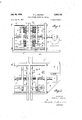
- FIGURE 1 is a general side elevation view of the switch
- FIGURE 2 is a section view of the switch taken at line 2-2 of FIGURE 1 and includes a block circuit diagram of typical electrical apparatus used in conjunction with the switch,
- FIGURE 3 is a top view of the switch of FIGURE 1,
- FIGURE 4a to 40 are detail views of one of the positioning slots in three successive positions during operation of the switch
- FIGURE 5 is a schematic diagram of the electrical control circuit for the invention.
- FIGURE 6 is a plan view of a modified embodiment of the switch.
- a flat base plate 12 having a generally rectangular configuration provides for general support and positioning of the parts of the switch.
- An electric motor 13 of a type in which the direction of rotation can be readily reversed is affixed to one end of the base plate 12.
- a speed reducer gear box 14 provides for decreasing the revolutions per minute obtained from the motor shaft 16 of the motor 13.
- a threaded shaft 17 is coupled to the output of the gear box 14, approximately one-half 18 of the shaft having a right-hand screw thread while the remainder 19 of the shaft has a left-hand screw thread.
- the shaft is supported by bearings 21 and 22 in first and second end panels 23 and 24 respectively.
- First end panel 23 is affixed to the base plate 12 by welding or by bolts to the base plate 12 adjacent the motor 13 while second end panel 24 is ailixed at the opposite end of the base plate.
- a central insulative plate 26 is disposed midway between the end panels 23 and 24 in parallel alignment therewith.
- the shaft 17 passes through a central aperture 27 in the insulative plate 26 and the screw t-hread direction is reversed in or near such aperture.
- the end plates 23 and 24 and the insulative plate 26 are mutually braced by four cross bars 28 bolted between corresponding corners of the end plates 23 and 24.
- Two sets 29 and 31 of stationary electrical contacts each including four large copper bus bars 32 are utilized in the switch.
- the two sets of bus bars 29 and 31 are bolted to opposite sides of the insulative plate 26 with corresponding bus bars 32 on opposite sides thereof being electrically connected by bolts 33.
- Each bus bar 32 of each set of bus bars is electrically insulated from the three other bus bars of the same set by narrow gaps 34.
- the bus bars 32 in each set are disposed in a quadrature configuration with adjacent edges of neighboring bus bars having beveled surfaces 36 facing away from the insulative plate 26. Thus there are provided gaps 34 between the bus bars 32 at spacings around the shaft 17.
- the beveled edges 36 at each gap 34 provide surfaces for mating with movable bridging contacts 37, which have appropriately curved contact surfaces which can seat against the beveled surfaces 36 and electrically bridge across a gap 34.
- Support and positioning of the bridging contacts 37 is provided by a first and second insulative disc 38 and 39 which are mounted on right hand and left hand screw thread portions 18 and 19 respectively of shaft 17, the discs each having a central aperture internally threaded to engage the threads of the shaft 17.
- each contact 37 is affixed to one end of a mounting rod 41, which is secured transversely to the insulative discs 38 and 39.
- Each rod 41 protrudes through a corresponding aperture 42 in the discs 37 and 38 and the protruded end of the rod provided with a cross pin 43 which prevents the protruded end of the pin from passing through the aperture 42, as particularly shown in FIG- URE 2.
- a coil spring 44 is placed around each rod 41 between the back of the contact 37 and the insulative discs 38 and 39 so that the pin is forced against the op posite side of the disc.
- the contacts 37 are not rigidly secured to the insulative discs 38 and 39, but may adjust to make best electrical contact with the beveled surfaces 36 when the discs are caused to advance theretoward.
- the discs 38 and 39 must be accurately positioned so that the bridging contacts 37 are aligned with the gaps 34 between the beveled surfaces 36.
- the angular position of the discs 38 and 39 must also be re-aligned during the switching operation so that the bridging contacts 37 are aligned with another gap 34 after the discs are rotated 90.
- the contacts 37 In the switching operation, the contacts 37 must, in sequence, be retracted from the bus bars 32, rotated 90", and then advanced toward the bus bars to make electrical contact in the new switch position.
- a slotted channel block 46 is provided as shown particularly in FIGURE 4a to 4c as well as FIGURE 1 to 3.
- Such channel block 46 has a channel or groove 47 which serves as a guide for engaging one of four protruding pins 48 disposed at 90" intervals around the periphery of the disc 38.
- the block 46 is thus disposed adjacent the disc 38 with the channel 47 transverse thereto.
- the block 46 may be disposed at any convenient portion of the disc 38 periphery, in the present instance being disposed at a 45 angle with respect to the base plate 12 by an angle bracket 50.
- One sidewall 49 of the block 46 is provided with a gap 51 through which the pins 48 can pass out of the channel.
- the other sidewall 52 is provided with a one way gate 53 having a spring loaded hinge 55 so that the gate 53 can open only inwardly into the channel in response to pressure, but cannot open outwardly.
- a pin 48 can enter the channel 47 through the gate 53, but only leave through gap 51.
- the gate 53 is generally disposed at a somewhat further distance from the bus bars 32 than is the gap 51.
- a pair of microswitches function as limit switches for the axial travel of the disc 38.
- a first microswitch 54 is conveniently disposed on the outside of the channel sidewall 49 for limiting maximum inward travel of the disc 38 by cutting off power to the motor 13 while a second microswitch 56 limits the maximum outward travel of the disc 38, causing the motor 13 to reverse direction of rotation.
- FIGURE 5 there is shown the control circuitry for operating the switch.
- the circuit is shown in a de-energized condition when the discs 38 and 39 are in the fully inward condition as shown in FIGURES 1, 2 and 3.
- Power is obtained through a dual power cable 69 coupled to a conventional 120 volt alternating current power source through a plug 71.
- a pushbutton switch 72 is momentarily depressed, causing current to energize a first relay coil 73 connected in series with the switch 72 across the power cable 69.
- First relay arm 74 is caused to close so that series connected rotor winding 76 and stator winding 77 of motor 13 are energized, the electrical current into and out of the rotor winding passing through reversing relay arms 78 and 79.
- the motor 13 turns, causing the discs 38 and 39 to be retracted away from the bus bars 32.
- the microswitch 54 connected in parallel with pushbutton switch 72, is of the normally closed type and is no longer held open when the disc 38 is retracted, making it unnecessary for the pushbutton switch to be manually depressed during the remainder of the switching cycle. When the discs 38 and 39 are fully retracted, the normally open microswitch 56 is closed by contact with the disc 38.
- a reversing relay coil 81 connected in series with the microswitch 56 across the first relay coil 73, is thus energized, causing holding relay contacts 82 of the reversing relay coil to close in parallel with the microswitch 56.
- Energization of reversing relay coil 81 also causes reversing relay contacts 78 and 29 to shift position and reverse the rotation of the motor 13' by reversing the direction of current flow through the rotor coil 76 relative to the current flow through stator coil 77.
- the discs 38 and 39 rotate as described with regard to FIGURE 4, and are advanced into the new switch position until the disc 38 causes the microswitch 54 to open and de-energize the motor 13. Each time the pushbutton switch 72 is closed the above-described sequence of operations occurs.
- the control circuit of FIGURE 5 and the apparatus associated with the slotted channel block 46 means of FIGURE 4a to 40 co-act to provide switching.
- the rotation of the shaft 17 causes the disc 38 to be retracted away from the bus bars 32.
- the disc 38 is prevented from rotating by a pin 48 which is engaged in the channel 47 and is forced against the inside surface of wall 49 by the friction between the threads of the disc 38 and shaft 17.
- the disc 38 moves laterally a suflicient distance for the pin 48 to pass through the gap 51.
- the disc 38 rotates for nearly one-quarter turn until another pin 48 strikes the outside surface of sidewall 52 as shown in FIGURE 4b, after which the disc 38 again moves longitudinally along the shaft 17. Subsequently, the pin 48 passes through the one-way gate 53 into the channel 47. Gate 53 immediately closes after the pin passes through .owing to the spring loaded hinge 55.
- the motor 13 reverses direction of rotation and the pin 48 is forced against the inner surface of the sidewall 52 and the one-way gate 53 as indicated in FIGURE 40.
- the pin remains engaged in the channel 47 until the microswitch 54 is opened by the disc 38, which occurs just after the bridging contacts 37 have made contact with the bus bars 32.
- a load 86 and a DC. power supply 87 may be electrically connected, as shown in FIGURE 2, between opposite pairs of bus bars 32. That is, the load 86 is connected across the bus bars 32 which, in the rectangular coordinate system, are in quadrants one and three while the power supply 87 is connected across the bus bars 32 in quadrants two and four.
- the switch 11 thus controls the direction of current flow through the load 86.
- FIGURE 2 there is indicated a broken-out section of the disc 38 with a radial hole 181.
- a nylon (polyarnide) slug 102 is pressed against the threads of the shaft 17 by a coil spring 103, which is secured by a threaded plug 184.
- the frictional characteristic of nylon has been found to be particularly desirable for the slug 102.
- a base plate 111, an electric motor 112, speed reducer 113, and end panels 114 and 116 have identical functions as the corresponding elements of the first switch.
- a threaded shaft 117 has a single thread direction.
- a pair of insulative rectangular plates 118 and 119 each have internally threaded apertures 121 and 122 which engage the threads of the shaft 117.
- the plates 118 and 119 are prevented from rotating by tracks 123 so that the plates can have only lateral motion.
- Bridging contacts 124 identical to the previous bridging contacts 37, are spring mounted on the plates 118 and 119 in the same manner as the contacts 37 are mounted to the discs 38 and 39.
- the contacts 124 mounted on plate 118 are disposed in a line transverse to the line of contacts on plate 119.
- a single set of four bus bars 126 are disposed in quadrature between the two plates 118 and 119 supported by insulated mounts 127. Both sides of the bus bars 126 are provided with beveled surfaces 128 to match the corresponding set of bridging contacts 124.
- a pair of microswitches 129 and 131 coupled to the motor 112 limit the extremes of travel in each direction.
- the switchof FIGURE 6 there are two switch positions.
- the bridging contacts 124 mounted on plate 118 electrically bridge between pairs of bus bars 126.
- the motor 112 is energized, rotating the threaded shaft 117 and causing plate 119 to move toward the bus bars 126 while the plate 118 is moved away from the bus bars.
- the bridging contacts 124 attached to the plate 119 make electrical contact with the bus bars 126 before the contacts associated with the plate 118 break electrical contact, thus providing the make before break feature.
- the plate 118 depresses the microswitch 129 which causes the motor 112 to be de-energized.
- a high current switch for reversing the direction of current from a source through a load, the combination comprising:
- a plurality of mutually insulated bridging contact means having a first position providing electrical contact across said gaps between said load and source contacts in said first and second quadrants and between said load and source contacts in said third and fourth quadrants, said bridging contacts having a second position providing electrical contact across said gaps between said source and load contacts in said second and third quadrants and between said load and source contacts in said first and fourth quadrants, and
- switching control means coupled to said bridging contacts and adapted to selectively move said bridging contacts transversely to said plane from said first switch position to said second switch position.
- (0) means moving said bridging contacts parallel to said axis and in alignment with said gaps for selectively electrically connecting together pairs of said bus bars
- a control circuit selectively energizing said moving means and including means for detecting and limiting extremes of movement of said bridging contacts.
- control means coupled to and selectively energizing said motor.
- a compact high current switch for changing the direction of current from a source through a load, said switch being of the class having:
- switch means selectively energizing said motor whereby said panel is movable along said shaft.
- a motor control circuit adapted to selectively change the direction of rotation of said motor whereby said bridging contacts may be sequentially withdrawn and advanced from said bus bars.
- said positioning means includes four indexing elements disposed at 90 increments around said rotatable support means, and a stationary guide adapted to sequentially engage said indexing elements.
- a compact high current switch comprising of the class having:
- each of said pin guides being adapted to sequentially disengage with one of said pins and engage an adjacent pin upon rotation of said shaft in said first direction whereby said sets of bridging contacts are mutually aligned and aligned with said gaps.
- a compact high current switch for reversing the direction of current through a load, comprising said switch being of the class having:
Description
July 26, 1966 w. L. DEXTER 3,253,145
HIGH CURRENT REVERSING SWITCH Filed May 26, 1964 4 Sheets-Sheet 1 INVENTOR.
WARREN L. DEXTER ATTORNEY.
July 26, 1966 w. L. DEXTER HIGH CURRENT REVERSING Filed May 26, 1964 POWER SUPPLY SWITCH 4 Sheets-Sheet 2 INVENTOR.
WARREN L. DEXTER ATTORNEY.
July 26, 1966 w. L. DEXTER 3,263,145
HIGH CURRENT REVERSING SWITCH Filed May 26. 196 4 Sheets-Sheet 5 INVENTOR.
WARREN L. DEXTER ATTORNEY.
July 26, 1966 w. L. DEXTER 3,263,145
HIGH CURRENT REVERSING SWITCH Filed May 26, 1964 4 Sheets-Sheet 4 INVENTOR. WARREN L. DEXTER ATTORNEY.
United States Patent 3,263,145 HIGH CURRENT REVERSING SWITCH Warren L. Dexter, Orinda, Calif., assignor toflle United States of America as represented by the United States Atomic Energy Commission Filed May 26, 1964, Ser. No. 370,388 Claims. (Cl. 318-266) The present invention relates to electrical switches and more particularly to a compact, motor-operated switch for controlling currents in the general order of 2000 amperes. The invention described herein was made in the course of, or under Contract W-7405-eng-48 with the United States Atomic Energy Commission.
The present invention is particularly useful with large charged particle guiding electromagnets, motors, and electrochemistry apparatus where direct current reversal must be accomplished, and in such usage replaces conventional double-pole, double-throw switch assemblies. The design of the invention has been directed toward providing a compact, remotely controllable, rugged, inexpensive switch with self-wiping contacts for maximum dependability. Many of the above advantages are obtained by eliminating redundancy of parts in the switch, that is, in the most advanced embodiment of the switch, every switching element, both stationary contacts and movable contacts, are all used in both switch positions. The switch was developed for operation in inaccessible regions such as are found adjacent high energy particle accelerators having a high radioactivity level, reliability being highly important in such usage.
In the physical arrangement of the switch, four stationary bus bar contacts may be considered as disposed in separate quadrants of a plane according to the rectangular coordinate system, each stationary contact being electrically insulated from adjacent contacts by narrow air gaps on the axes. Two opposite contacts (for instance, contacts in quadrants one and three) are connected to a load while the remaining two contacts (in quadrants two and four) are connected to a power source. To electrically connect the power source to the load, at least two bridging contacts are provided to connect selected pairs of stationary contacts (for example, electrically con-necting the stationary contact in quadrant one to the stationary contact in quadrant two and connecting the contact in quadrant three to the contact in quadrant four). The two bridging contacts are aligned with one of the axes (in this example the Y axis) and electrically and physically bridge the air gap between quadrants. To switch, the bridging contacts are retracted from the stationary contacts to open the electrical connections. Bridging contacts are then advanced toward the stationary contacts in alignment with the alternate perpendicular axis (the X axis in the example) and electrically bridge between alternate pairs of stationary contacts (electrically connecting stationary contacts in quadrants one and four and stationary contacts in quadrants two and three).
To further improve the efiiciency of the switch, two electrically parallel sets of contacts can be provided in each unit and operated in synchronism.
There is no necessity for making external electrical connections direct to the bridging contacts, since such contacts serve only as an electrical bridging means between sets of stationary contacts. Thus the ruggedness and dependability of the switch is greatly enhanced since no electrical connections are maintained with movable switch elements.
It is an object of the present invention to provide a new high current switch suitable for use in regions where access is limited.
It is another object of the present invention to provide a more compact very high current switch.
It is another object of the present invention to provide a relatively inexpensive switch for high currents with eflicient utilization of space and materials.
It is another object of the present invention to provide a high current switch which may readily be remotely controlled.
It is another object of the present invention to provide a high current switch which is rugged and highly dependable.
The invention will be better understood by reference to the following specification together with the accompanying drawings of which:
FIGURE 1 is a general side elevation view of the switch,
FIGURE 2 is a section view of the switch taken at line 2-2 of FIGURE 1 and includes a block circuit diagram of typical electrical apparatus used in conjunction with the switch,
FIGURE 3 is a top view of the switch of FIGURE 1,
FIGURE 4a to 40 are detail views of one of the positioning slots in three successive positions during operation of the switch,
FIGURE 5 is a schematic diagram of the electrical control circuit for the invention, and
FIGURE 6 is a plan view of a modified embodiment of the switch.
Referring now to FIGURES 1, 2 and 3 in conjunction, the various major components of the switch 11 will be described. A flat base plate 12 having a generally rectangular configuration provides for general support and positioning of the parts of the switch. An electric motor 13 of a type in which the direction of rotation can be readily reversed is affixed to one end of the base plate 12. A speed reducer gear box 14 provides for decreasing the revolutions per minute obtained from the motor shaft 16 of the motor 13.
A threaded shaft 17 is coupled to the output of the gear box 14, approximately one-half 18 of the shaft having a right-hand screw thread while the remainder 19 of the shaft has a left-hand screw thread. The shaft is supported by bearings 21 and 22 in first and second end panels 23 and 24 respectively. First end panel 23 is affixed to the base plate 12 by welding or by bolts to the base plate 12 adjacent the motor 13 while second end panel 24 is ailixed at the opposite end of the base plate. Thus each end of the shaft 17 is supported in the bearings 21 and 22. A central insulative plate 26 is disposed midway between the end panels 23 and 24 in parallel alignment therewith. The shaft 17 passes through a central aperture 27 in the insulative plate 26 and the screw t-hread direction is reversed in or near such aperture. The end plates 23 and 24 and the insulative plate 26 are mutually braced by four cross bars 28 bolted between corresponding corners of the end plates 23 and 24.
Two sets 29 and 31 of stationary electrical contacts each including four large copper bus bars 32 are utilized in the switch. The two sets of bus bars 29 and 31 are bolted to opposite sides of the insulative plate 26 with corresponding bus bars 32 on opposite sides thereof being electrically connected by bolts 33. Each bus bar 32 of each set of bus bars is electrically insulated from the three other bus bars of the same set by narrow gaps 34. The bus bars 32 in each set are disposed in a quadrature configuration with adjacent edges of neighboring bus bars having beveled surfaces 36 facing away from the insulative plate 26. Thus there are provided gaps 34 between the bus bars 32 at spacings around the shaft 17.
The beveled edges 36 at each gap 34 provide surfaces for mating with movable bridging contacts 37, which have appropriately curved contact surfaces which can seat against the beveled surfaces 36 and electrically bridge across a gap 34. In the present instance, the bridging =3 contacts 37 are copper half cylinders with the curved surfaces of the half-cylinder being disposed for contacting adjacent beveled surfaces 36. Support and positioning of the bridging contacts 37 is provided by a first and second insulative disc 38 and 39 which are mounted on right hand and left hand screw thread portions 18 and 19 respectively of shaft 17, the discs each having a central aperture internally threaded to engage the threads of the shaft 17. In the embodiment of the invention shown in FIGURE 1 to 3, six of the bridging contacts 37 are disposed in a row on a diameter of each of the discs 38 and 39. Each contact 37 is affixed to one end of a mounting rod 41, which is secured transversely to the insulative discs 38 and 39. Each rod 41 protrudes through a corresponding aperture 42 in the discs 37 and 38 and the protruded end of the rod provided with a cross pin 43 which prevents the protruded end of the pin from passing through the aperture 42, as particularly shown in FIG- URE 2. A coil spring 44 is placed around each rod 41 between the back of the contact 37 and the insulative discs 38 and 39 so that the pin is forced against the op posite side of the disc. Thus, the contacts 37 are not rigidly secured to the insulative discs 38 and 39, but may adjust to make best electrical contact with the beveled surfaces 36 when the discs are caused to advance theretoward.
The discs 38 and 39 must be accurately positioned so that the bridging contacts 37 are aligned with the gaps 34 between the beveled surfaces 36. The angular position of the discs 38 and 39 must also be re-aligned during the switching operation so that the bridging contacts 37 are aligned with another gap 34 after the discs are rotated 90. In the switching operation, the contacts 37 must, in sequence, be retracted from the bus bars 32, rotated 90", and then advanced toward the bus bars to make electrical contact in the new switch position.
To eifect such switching operation, a slotted channel block 46 is provided as shown particularly in FIGURE 4a to 4c as well as FIGURE 1 to 3. Such channel block 46 has a channel or groove 47 which serves as a guide for engaging one of four protruding pins 48 disposed at 90" intervals around the periphery of the disc 38. The block 46 is thus disposed adjacent the disc 38 with the channel 47 transverse thereto. The block 46 may be disposed at any convenient portion of the disc 38 periphery, in the present instance being disposed at a 45 angle with respect to the base plate 12 by an angle bracket 50. One sidewall 49 of the block 46 is provided with a gap 51 through which the pins 48 can pass out of the channel. The other sidewall 52 is provided with a one way gate 53 having a spring loaded hinge 55 so that the gate 53 can open only inwardly into the channel in response to pressure, but cannot open outwardly. Thus a pin 48 can enter the channel 47 through the gate 53, but only leave through gap 51. The gate 53 is generally disposed at a somewhat further distance from the bus bars 32 than is the gap 51.
As shown in FIGURE 3 and schematically in FIGURE 5, a pair of microswitches function as limit switches for the axial travel of the disc 38. A first microswitch 54 is conveniently disposed on the outside of the channel sidewall 49 for limiting maximum inward travel of the disc 38 by cutting off power to the motor 13 while a second microswitch 56 limits the maximum outward travel of the disc 38, causing the motor 13 to reverse direction of rotation.
Referring particularly to FIGURE 5, there is shown the control circuitry for operating the switch. The circuit is shown in a de-energized condition when the discs 38 and 39 are in the fully inward condition as shown in FIGURES 1, 2 and 3. Power is obtained through a dual power cable 69 coupled to a conventional 120 volt alternating current power source through a plug 71. To start the switching cycle, a pushbutton switch 72 is momentarily depressed, causing current to energize a first relay coil 73 connected in series with the switch 72 across the power cable 69. First relay arm 74 is caused to close so that series connected rotor winding 76 and stator winding 77 of motor 13 are energized, the electrical current into and out of the rotor winding passing through reversing relay arms 78 and 79. The motor 13 turns, causing the discs 38 and 39 to be retracted away from the bus bars 32. The microswitch 54, connected in parallel with pushbutton switch 72, is of the normally closed type and is no longer held open when the disc 38 is retracted, making it unnecessary for the pushbutton switch to be manually depressed during the remainder of the switching cycle. When the discs 38 and 39 are fully retracted, the normally open microswitch 56 is closed by contact with the disc 38. A reversing relay coil 81, connected in series with the microswitch 56 across the first relay coil 73, is thus energized, causing holding relay contacts 82 of the reversing relay coil to close in parallel with the microswitch 56. Energization of reversing relay coil 81 also causes reversing relay contacts 78 and 29 to shift position and reverse the rotation of the motor 13' by reversing the direction of current flow through the rotor coil 76 relative to the current flow through stator coil 77. The discs 38 and 39 rotate as described with regard to FIGURE 4, and are advanced into the new switch position until the disc 38 causes the microswitch 54 to open and de-energize the motor 13. Each time the pushbutton switch 72 is closed the above-described sequence of operations occurs.
The control circuit of FIGURE 5 and the apparatus associated with the slotted channel block 46 means of FIGURE 4a to 40 co-act to provide switching. As indicated in FIGURE 4a, immediately after the switch 72 is closed to activate the motor 13 the rotation of the shaft 17 causes the disc 38 to be retracted away from the bus bars 32. The disc 38 is prevented from rotating by a pin 48 which is engaged in the channel 47 and is forced against the inside surface of wall 49 by the friction between the threads of the disc 38 and shaft 17. Eventually, the disc 38 moves laterally a suflicient distance for the pin 48 to pass through the gap 51. Since the pin 48 is no longer engaged in channel 47, the disc 38 rotates for nearly one-quarter turn until another pin 48 strikes the outside surface of sidewall 52 as shown in FIGURE 4b, after which the disc 38 again moves longitudinally along the shaft 17. Subsequently, the pin 48 passes through the one-way gate 53 into the channel 47. Gate 53 immediately closes after the pin passes through .owing to the spring loaded hinge 55. When the disc 38 closes the microswitch 56, the motor 13 reverses direction of rotation and the pin 48 is forced against the inner surface of the sidewall 52 and the one-way gate 53 as indicated in FIGURE 40. The pin remains engaged in the channel 47 until the microswitch 54 is opened by the disc 38, which occurs just after the bridging contacts 37 have made contact with the bus bars 32.
As discussed previously, a load 86 and a DC. power supply 87 may be electrically connected, as shown in FIGURE 2, between opposite pairs of bus bars 32. That is, the load 86 is connected across the bus bars 32 which, in the rectangular coordinate system, are in quadrants one and three while the power supply 87 is connected across the bus bars 32 in quadrants two and four. The switch 11 thus controls the direction of current flow through the load 86.
It is desirable to maintain a certain controllable degree of friction between the screw threads of the shaft 17 and the disc 38 and 39 to insure proper rotation of the discs. In FIGURE 2 there is indicated a broken-out section of the disc 38 with a radial hole 181. A nylon (polyarnide) slug 102 is pressed against the threads of the shaft 17 by a coil spring 103, which is secured by a threaded plug 184. The frictional characteristic of nylon has been found to be particularly desirable for the slug 102.
Numerous variations in the construction and operation of the switch are possible. For instance, it is sometimes desirable to obtain a make before break type of switching for large inductive loads. That is, during Switching, the new switch connections are made. before the old connections are broken. For such operation, a modified version of the switch is provided as shown in FIGURE 6.
In such switch a base plate 111, an electric motor 112, speed reducer 113, and end panels 114 and 116 have identical functions as the corresponding elements of the first switch. A threaded shaft 117 has a single thread direction. A pair of insulative rectangular plates 118 and 119 each have internally threaded apertures 121 and 122 which engage the threads of the shaft 117. The plates 118 and 119 are prevented from rotating by tracks 123 so that the plates can have only lateral motion. Bridging contacts 124, identical to the previous bridging contacts 37, are spring mounted on the plates 118 and 119 in the same manner as the contacts 37 are mounted to the discs 38 and 39. However, the contacts 124 mounted on plate 118 are disposed in a line transverse to the line of contacts on plate 119. A single set of four bus bars 126 are disposed in quadrature between the two plates 118 and 119 supported by insulated mounts 127. Both sides of the bus bars 126 are provided with beveled surfaces 128 to match the corresponding set of bridging contacts 124. A pair of microswitches 129 and 131 coupled to the motor 112 limit the extremes of travel in each direction.
-In the operation of the switchof FIGURE 6, there are two switch positions. In the first position, shown in FIGURE 6, the bridging contacts 124 mounted on plate 118 electrically bridge between pairs of bus bars 126. In the switching operation, the motor 112 is energized, rotating the threaded shaft 117 and causing plate 119 to move toward the bus bars 126 while the plate 118 is moved away from the bus bars. The bridging contacts 124 attached to the plate 119 make electrical contact with the bus bars 126 before the contacts associated with the plate 118 break electrical contact, thus providing the make before break feature. Eventually, the plate 118 depresses the microswitch 129 which causes the motor 112 to be de-energized.
It will 'be noted that the modified version of the switch just described will not have the current carrying capability of the first described switch, since only half the :bridging contacts 124 are in use at one time. However, the same basic quadrature configuration is utilized.
In use, it has been found advantageous in both switches to allow one of the bridging contacts 37 or 124 to project ahead of the accompanying contacts in a set so that when the bridging contacts are being advanced toward the bus bars, such projected contact Will bridge the bus bars slightly before the accompanying contacts so that the projected contact will receive any arcs produced. Then the remaining contacts remain smooth and unpitted so that a 'low ohmage current path is maintained.
Thus while the invention has been disclosed with respect to particular embodiments, it will be apparent to those skilled in the art that numerous variations and modifications may be made within the spirit and scope of the invention and thus it is not intended to limit the invention except as defined in the following claims.
What is claimed is:
1. In a high current switch for reversing the direction of current from a source through a load, the combination comprising:
(a) a first pair of source contacts connected to said source,
(b) a second pair of load contacts connected to said load, said load contacts and said source contacts being disposed in first, second, third and fourth quadrants of a rectangular co-ordinate system having perpendicular axes defining said quad-rants with said load contacts being disposed in odd numbered quadrants and said source contacts being disposed in even numbered quadrants, said source and load contacts being electrically isolated from each other along said axes,
(c) a plurality of mutually insulated bridging contact means having a first position providing electrical contact across said gaps between said load and source contacts in said first and second quadrants and between said load and source contacts in said third and fourth quadrants, said bridging contacts having a second position providing electrical contact across said gaps between said source and load contacts in said second and third quadrants and between said load and source contacts in said first and fourth quadrants, and
(d) switching control means coupled to said bridging contacts and adapted to selectively move said bridging contacts transversely to said plane from said first switch position to said second switch position.
2. In a high current reversing switch, the combination comprising:
(a) a set of four co-planar bus bar stationary contacts disposed in quadrature about a reference axis with a separate bus bar contact in each of four quadrants of said axis, said bus bars having facing edges electrically separated by gaps,
(b) a plurality of bridging contacts alignable with said gaps,
(0) means moving said bridging contacts parallel to said axis and in alignment with said gaps for selectively electrically connecting together pairs of said bus bars, and
(d) a control circuit selectively energizing said moving means and including means for detecting and limiting extremes of movement of said bridging contacts.
3. In a compact high current switch of the class having:
(a) a threaded rotatable shaft,
(b) a reversible motor coupled to said shaft, the com- :bination comprising:
(c) at least one set of four stationary electrical contacts each contact being disposed in one of four quadrants about said shaft and being transverse thereto, each of said stationary contacts being electrically spaced from adjacent stationary contact by narrow gaps,
- (d) insulative supportm-eans threaded to said shaft,
(e) a plurality of bridging contacts afiixed to said support means and adapted to simultaneously engage the edges of selected pairs of said bus bars on each side of said gaps to electrically bridge therebetween, and
.(f) control means coupled to and selectively energizing said motor.
4. In a compact high current switch for changing the direction of current from a source through a load, said switch being of the class having:
(a) a rotatable thread-ed shaft,
(b) a motor coupled to said shaft, the combination comprising:
(c) four stationary contacts having means for connection to said source and said load and disposed in a plane transverse to said shaft, each said stationary contact being in a separate quad-rant around said shaft and being spaced by small insulative gaps from adjacent contacts,
(d) an insulative panel threaded to said shaft,
(e) a plurality of bridging contacts affixed to said panel and disposed on opposite sides of said shaft,
(f) means aligning said bridging contacts with one of said gaps, and
(g) switch means selectively energizing said motor whereby said panel is movable along said shaft.
5. In a compact high current switch of the class having:
(a) a threaded rotatable shaft,
(b) a motor operatively coupled to said shaft, the combination comprising:
(c) four stationary bus bar contacts disposed in quadrature around and transverse to said shaft, said bus bar contacts being electrically separated by gaps,
(d) an insulative mounting panel threaded on said shaft,
(e) at least two bridging contacts for electrically shorting between said stationary contacts and affixed to said panel on diametrically opposite sides of said shaft,
(f) means selectively aligning said bridging contacts with said gaps between said bus bars, and
(g) a control circuit coupled to said motor for moving said panel along said shaft and limiting extremes of lineal travel of said panel along said shaft.
6. In a high current reversing switch of the class having:
(a) a threaded shaft,
(b) a reversible motor coupled to said shaft for controlled rotation thereof, the combination comprising:
(c) a set of four bus bars each disposed in a separate geometrical quadrant around said shaft in transverse rotation thereto, adjacent bus bars being spaced apart by insulative gaps,
(d) a rotatable insulative support means threaded to said shaft,
(e) a plurality of bridging contacts affixed to said support means and disposed on diametrically opposing sides of said shaft,
(f) positioning means coupled to said support means and adapted to angularly align said bridging contacts with selected opposing pairs of said gaps, and
(g) a motor control circuit adapted to selectively change the direction of rotation of said motor whereby said bridging contacts may be sequentially withdrawn and advanced from said bus bars.
7. The apparatus of claim 6 further characterized in that said positioning means includes four indexing elements disposed at 90 increments around said rotatable support means, and a stationary guide adapted to sequentially engage said indexing elements.
8. A compact high current switch comprising of the class having:
(a) a threaded shaft having a right hand thread portion and a left hand thread portion,
(b) a reversible motor coupled to said shaft, the combination comprising:
() a set of four electrical circuit elements disposed in separate quadrants around said shaft at the juncture between said right and said left hand thread portions, each of said elements being an electrically unified stationary conductor, said elements being spaced apart by gaps from elements in adjacent quadrants,
(d) a first and a second circular insulative support coaxially threaded onto said right and said left hand thread portions respectively,
(e) a first and a second set of bridging contacts affixed to said first and said second insulative supports respectively, each of said sets of bridging contacts being disposed on a diameter of said support,
(f) a first and a second set of four pins each disposed at 90 intervals around the rim of said first and said second insulative supports respectively,
(g) a motor control circuit adapted to sequentially energize said motor to rotate said shaft in a first direction and then in a second direction and subsequently stop said shaft,
(h) a start switch connected to said motor control circuit, and
(i) a first and a second pin guide disposed proximal the periphery of said first and said second supports respectively, each of said pin guides being adapted to sequentially disengage with one of said pins and engage an adjacent pin upon rotation of said shaft in said first direction whereby said sets of bridging contacts are mutually aligned and aligned with said gaps.
9. A compact high current switch for reversing the direction of current through a load, comprising said switch being of the class having:
(a) a threaded shaft,
(b) a reversible motor coupled to said shaft, said switch comprising:
(0) a set of four stationary contacts each disposed in separate quadrants around said shaft and in transverse relationship thereto, each of said stationary con tacts being separated from adjacent stationary contacts by a gap whereby two gaps at spacings are provided around said shaft,
(d) a first and a second insulative panel threaded to said shaft,
(e) a first set and a transverse second set of bridging contacts resiliently affixed to said first and second panels respectively and aligned with said gaps and each having a width exceeding that of said gaps, each of said sets including at least two bridging contacts disposed on directly opposite sides of said shaft,
(f) means preventing rotation of said panels,
(g) a motor control circuit coupled to said motor and adapted to selectively control the direction of rotation of said motor during switching, and
(h) position detecting means coupled to said control circuit whereby alternate extremes of position of said panels may be detected and said motor de-activated.
10. The apparatus of claim 9 wherein said first set and said second set of bridging contacts (e) are adapted to simultaneously contact said stationary contacts (0) across said gaps at an intermediate position of said panels (d) between said extremes.
References Cited by the Examiner UNITED STATES PATENTS 2,435,440 2/1948 Graham 318267 2,555,025 5/ 1951 Cheek 200-4 X 2,566,824 9/1951 Carlson ZOO-47 3,047,683 7/1962 Shlesinger 200158 X 3,200,314 8/1965 Iroler 318-467 X References Cited by the Applicant UNITED STATES PATENTS 1,257,533 2/1918 Sachs.
ORISL. RADER, Primary Examiner. I. C. BERENZWEIG, Assistant Examiner.
Claims (1)
- 9. A COMPACT HIGH CURRENT SWITCH FOR REVERSING THE DIRECTION OF CURRENT THROUGH A LOAD, COMPRISING SAID SWITCH BEING OF THE CLASS HAVING: (A) A THREADED SHAFT, (B) A REVERSIBLE MOTOR COUPLED TO SAID SHAFT, SAID SWITCH COMPRISING: (C) A SET OF FOUR STATIONAY CONTACTS EACH DIPOSED IN SEPARATE QUADRANTS AROUND SAID SHAFT AND IN TRANSVERSE RELATIONSHIP THERETO, EACH OF SAID STATIONARY CONTACTS BEING SEPARATED FROM ADJACENT STATIONARY CONTACTS BY A GAP WHEREBY TWO GAPS AT 90* SPACINGS ARE PROVIDED AROUND SAID SHAFT, (D) A FIRST AND A SECOND INSULATIVE PANEL THREADED TO SAID SHAFT, (E) A FIRST SET AND A TRANSVERSE SECOND SET OF BRIDGING CONTACTS RESILIENTLY AFFIXED TO SAID FIRST AND SECOND PANELS RESPECTIVELY AND ALIGNED WITH SAID GAPS AND EACH HAVING A WIDTH EXCEEDING THAT OF SAID GAPS, EACH OF SAID SETS INCLUDING AT LEAST TWO BRIDGING CONTACTS DISPOSED ON DIRECTLY OPPOSITE SIDES OF SAID SHAFT, (F) MEANS PREVENTING ROTATION OF SAID PANELS, (G) A MOTOR CONTROL CIRCUIT COUPLED TO SAID MOTOR AND ADAPTED TO SELECTIVELY CONTROL THE DIRECTION OF ROTATION OF SAID MOTOR DURING SWITCHING, AND (H) POSITION DETECTING MEANS COUPLED TO POSITION OF SAID CIRCUIT WHEREBY ALTERNATE EXTREMES OF POSITION OF SAID PANELS MAY BE DETECTED AND SAID MOTOR DE-ACTIVATED.
Priority Applications (5)
| Application Number | Priority Date | Filing Date | Title |
|---|---|---|---|
| US370388A US3263145A (en) | 1964-05-26 | 1964-05-26 | High current reversing switch |
| GB17349/65A GB1068274A (en) | 1964-05-26 | 1965-04-23 | High current reversing switch |
| FR18096A FR1445581A (en) | 1964-05-26 | 1965-05-24 | Reversing switch for high currents |
| CH731165A CH428895A (en) | 1964-05-26 | 1965-05-25 | Reversing switch for high currents |
| BE664426D BE664426A (en) | 1964-05-26 | 1965-05-25 |
Applications Claiming Priority (1)
| Application Number | Priority Date | Filing Date | Title |
|---|---|---|---|
| US370388A US3263145A (en) | 1964-05-26 | 1964-05-26 | High current reversing switch |
Publications (1)
| Publication Number | Publication Date |
|---|---|
| US3263145A true US3263145A (en) | 1966-07-26 |
Family
ID=23459427
Family Applications (1)
| Application Number | Title | Priority Date | Filing Date |
|---|---|---|---|
| US370388A Expired - Lifetime US3263145A (en) | 1964-05-26 | 1964-05-26 | High current reversing switch |
Country Status (5)
| Country | Link |
|---|---|
| US (1) | US3263145A (en) |
| BE (1) | BE664426A (en) |
| CH (1) | CH428895A (en) |
| FR (1) | FR1445581A (en) |
| GB (1) | GB1068274A (en) |
Cited By (4)
| Publication number | Priority date | Publication date | Assignee | Title |
|---|---|---|---|---|
| US3394292A (en) * | 1964-09-10 | 1968-07-23 | Bunker Ramo | Rotary position indicator and control station |
| US3470503A (en) * | 1968-02-07 | 1969-09-30 | Atomic Energy Commission | Multi-contact selector switch for high currents |
| US4163135A (en) * | 1978-01-30 | 1979-07-31 | The United States Of America As Represented By The Secretary Of The Navy | High current switches using multi-louvered contact strips |
| US4518837A (en) * | 1983-07-12 | 1985-05-21 | United Technologies Corporation | Electrical switch for induction heating system |
Families Citing this family (1)
| Publication number | Priority date | Publication date | Assignee | Title |
|---|---|---|---|---|
| DE9300144U1 (en) * | 1993-01-08 | 1993-03-04 | Elektrometall Wirth + Co., 6104 Seeheim-Jugenheim, De |
Citations (6)
| Publication number | Priority date | Publication date | Assignee | Title |
|---|---|---|---|---|
| US1257533A (en) * | 1915-02-18 | 1918-02-26 | Joseph Sachs | Electric switch. |
| US2435440A (en) * | 1944-08-14 | 1948-02-03 | Gen Electric | Reversible motor drive |
| US2555025A (en) * | 1948-02-20 | 1951-05-29 | United States Steel Corp | Bus bar reversing switch |
| US2566824A (en) * | 1950-10-28 | 1951-09-04 | Gale K Carlson | Limit switch |
| US3047683A (en) * | 1961-03-22 | 1962-07-31 | Jr Bernard Edward Shlesinger | Multiple contact switch |
| US3200314A (en) * | 1963-05-03 | 1965-08-10 | Iroler Maurice Benton | Tuner antenna control |
-
1964
- 1964-05-26 US US370388A patent/US3263145A/en not_active Expired - Lifetime
-
1965
- 1965-04-23 GB GB17349/65A patent/GB1068274A/en not_active Expired
- 1965-05-24 FR FR18096A patent/FR1445581A/en not_active Expired
- 1965-05-25 CH CH731165A patent/CH428895A/en unknown
- 1965-05-25 BE BE664426D patent/BE664426A/xx unknown
Patent Citations (6)
| Publication number | Priority date | Publication date | Assignee | Title |
|---|---|---|---|---|
| US1257533A (en) * | 1915-02-18 | 1918-02-26 | Joseph Sachs | Electric switch. |
| US2435440A (en) * | 1944-08-14 | 1948-02-03 | Gen Electric | Reversible motor drive |
| US2555025A (en) * | 1948-02-20 | 1951-05-29 | United States Steel Corp | Bus bar reversing switch |
| US2566824A (en) * | 1950-10-28 | 1951-09-04 | Gale K Carlson | Limit switch |
| US3047683A (en) * | 1961-03-22 | 1962-07-31 | Jr Bernard Edward Shlesinger | Multiple contact switch |
| US3200314A (en) * | 1963-05-03 | 1965-08-10 | Iroler Maurice Benton | Tuner antenna control |
Cited By (4)
| Publication number | Priority date | Publication date | Assignee | Title |
|---|---|---|---|---|
| US3394292A (en) * | 1964-09-10 | 1968-07-23 | Bunker Ramo | Rotary position indicator and control station |
| US3470503A (en) * | 1968-02-07 | 1969-09-30 | Atomic Energy Commission | Multi-contact selector switch for high currents |
| US4163135A (en) * | 1978-01-30 | 1979-07-31 | The United States Of America As Represented By The Secretary Of The Navy | High current switches using multi-louvered contact strips |
| US4518837A (en) * | 1983-07-12 | 1985-05-21 | United Technologies Corporation | Electrical switch for induction heating system |
Also Published As
| Publication number | Publication date |
|---|---|
| FR1445581A (en) | 1966-07-15 |
| CH428895A (en) | 1967-01-31 |
| BE664426A (en) | 1965-09-16 |
| GB1068274A (en) | 1967-05-10 |
Similar Documents
| Publication | Publication Date | Title |
|---|---|---|
| US3419827A (en) | Indexing microwave switch | |
| US3023348A (en) | Motor control system | |
| US3581188A (en) | Switching device for on-load tap changers of regulating transformers | |
| US3042847A (en) | Rotor controlled stepper motor | |
| US3263145A (en) | High current reversing switch | |
| US2785242A (en) | Tap-changers | |
| AU659829B2 (en) | Mechanical interlock for a pair of electromagnetic switches | |
| US2640955A (en) | Electromagnetic straight-line motor | |
| US2884581A (en) | Electric motor control system | |
| US2910558A (en) | Electrical phase sequence switch | |
| US3598934A (en) | Multiple pole switch for producing simultaneous opposite switching operations | |
| US1155157A (en) | Reversing-switch. | |
| US3609267A (en) | Electric load changeover switch with movable contacts insertable in a rotary shaft, and arc discharge channels | |
| EP0147036A1 (en) | Circuit breaker assembly | |
| US2484576A (en) | Interphase winding and ratio adjuster switching arrangement for polyphase transformers | |
| US3875354A (en) | Load tap changing mechanism having constant duty cycle | |
| US2416229A (en) | Control apparatus for reversible motors | |
| US2253557A (en) | Combined limit switch and relay | |
| US1971130A (en) | Remote control device | |
| US2747116A (en) | Reversible direct-current motor | |
| GB1154692A (en) | A Stepping Motor. | |
| US2435438A (en) | Electric switch | |
| US2595414A (en) | Electric switch control station | |
| US2316678A (en) | Circuit controller | |
| US3243676A (en) | Motor driven automatic stepping drive for a rotatable shaft, including means for positively locking the shaft in a selected position and dynamic braking for the motor |