US325552A - Fish-pond trunk - Google Patents
Fish-pond trunk Download PDFInfo
- Publication number
- US325552A US325552A US325552DA US325552A US 325552 A US325552 A US 325552A US 325552D A US325552D A US 325552DA US 325552 A US325552 A US 325552A
- Authority
- US
- United States
- Prior art keywords
- pond
- water
- fish
- trunk
- gate
- Prior art date
- Legal status (The legal status is an assumption and is not a legal conclusion. Google has not performed a legal analysis and makes no representation as to the accuracy of the status listed.)
- Expired - Lifetime
Links
- XLYOFNOQVPJJNP-UHFFFAOYSA-N water Substances O XLYOFNOQVPJJNP-UHFFFAOYSA-N 0.000 description 18
- 238000005192 partition Methods 0.000 description 9
- 238000001363 water suppression through gradient tailored excitation Methods 0.000 description 4
- 241000251468 Actinopterygii Species 0.000 description 3
- 235000006576 Althaea officinalis Nutrition 0.000 description 3
- 238000010276 construction Methods 0.000 description 2
- CIWBSHSKHKDKBQ-JLAZNSOCSA-N Ascorbic acid Chemical compound OC[C@H](O)[C@H]1OC(=O)C(O)=C1O CIWBSHSKHKDKBQ-JLAZNSOCSA-N 0.000 description 1
- 230000001105 regulatory effect Effects 0.000 description 1
Images
Classifications
-
- E—FIXED CONSTRUCTIONS
- E02—HYDRAULIC ENGINEERING; FOUNDATIONS; SOIL SHIFTING
- E02B—HYDRAULIC ENGINEERING
- E02B13/00—Irrigation ditches, i.e. gravity flow, open channel water distribution systems
- E02B13/02—Closures for irrigation conduits
Definitions
- This invention relates to trunks used in connection with iish-ponds for regulating and utilizing the flow of water and forpreventing the escape of fish.
- This invention consists in the combination of the parts hereinafter described, by which a water-wheel may be operated by the overliow ⁇ water of the pond, or the overflow water may be allowed to pass off without operating the water-wheel, or the whole ofthe water in the pond may be utilized for driving the said water-wheel, or may be allowed to pass ofi' and cmptythe pond without turning it. In whichever way the water is allowed to pass one, the escape of iish from the pond is prevented.
- A is the cross-section oi' the dani of a lishpond, the top c of which may be used for a carriage-road, if desired.
- B is a passage in thelower part of the dam for letting the water ont of the ish-pond.
- C is another passage in the lower part of the dam for conducting the water let out from the iish-pond to the nndershot watenwheel J.
- H represents the level of the water in the fish-pond.
- G is a grating which covers the opening between the pond and the chamber D, in which are situated the gates which control the ilow of water from the pond into the passages B and G.
- the grating G prevents the escape of fish from the pond, and is so constructed that it may be removed, if necessary.
- the undershot water-wheel J is of ordinary construction, and runs in bearings j, attached lto the side frames, j', which prevent the escape of the water past the sides of the wheel.
- the chamberD is provided with a partition, d, which extends upward to about the usual level of the water in the pond, and au opening, d', is provided in the lower part of the partition d for the direct passage of water from the pond to passages B and C.
- Eis the transfer-gate provided with an opening, e, in it, and a. long shaft, e', extending upward through an opening in the top of the chamber D, by which it may be raised orlowered.
- F is the low-water gate, which works in connection with the opening d in the partition d, and is provided with the long shaft f, eX- tending upward through an opening in the top of the chamber D, by which it may be raised or lowered.
- the overflow water of the pond passes over thetop of partition d, in the direction of the arrows, and passes oii down the passage B. If the transfer-gate Eshould belowered so as to cover the end of passage B, the overflow water will pass through the opening e in the said gate down passage C, and will drive the waterwheel J. Should the water in the pond be lower than the top of partition dthe low-water gate can be opened. rI ⁇ he water from the'pond will then pass directly to the transfer-gate E. Ii' this is lowered, the water will pass down passage G and drive the water-wheel J.
Landscapes
- Engineering & Computer Science (AREA)
- General Engineering & Computer Science (AREA)
- Mechanical Engineering (AREA)
- Civil Engineering (AREA)
- Structural Engineering (AREA)
- Farming Of Fish And Shellfish (AREA)
Description
(No Model.)
W. s. MALLARD.
FISH POND TRUNK.
Patented Sept. l, 1885.
No.A 325,552.
mVBNToR BY www@ ATTORNEYS.
UNITED STATES PATENT EiEicEo VILLIAM S. MALLARD, OF DARIEN, GEORGIA.
FISH-POND TRUNK.
SPECIFICATION forming part of 4Letters Patent No. 325,552, dated September l, 1885.
Application filed April B, 1885.
To all whom it may concern:
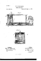
Be it known that I, WILLIAM S. MALLARD, of Darien, McIntosh county, Georgia, have invented a new and Improved Fish Pond Trunk; and I do hereby declare the following to be a full, clear, and exact description of the same, reference being had to the accompanying drawings, forming a part of this speciiical tion, in which- Figure 1 is a cross-section through a portion of the dam inclosi ng a fish-pond, and shows the construction of the trunk. Fig. 2 is a crosssection through the transfergate chamber, taken on the line .fr in Fig. 1.
This invention relates to trunks used in connection with iish-ponds for regulating and utilizing the flow of water and forpreventing the escape of fish. Y
This invention consists in the combination of the parts hereinafter described, by which a water-wheel may be operated by the overliow` water of the pond, or the overflow water may be allowed to pass off without operating the water-wheel, or the whole ofthe water in the pond may be utilized for driving the said water-wheel, or may be allowed to pass ofi' and cmptythe pond without turning it. In whichever way the water is allowed to pass one, the escape of iish from the pond is prevented.
In the accompanying drawings similar letters of reference indicate corresponding parts in all the gures.
A is the cross-section oi' the dani of a lishpond, the top c of which may be used for a carriage-road, if desired.
B is a passage in thelower part of the dam for letting the water ont of the ish-pond.
C is another passage in the lower part of the dam for conducting the water let out from the iish-pond to the nndershot watenwheel J.
H represents the level of the water in the fish-pond. G is a grating which covers the opening between the pond and the chamber D, in which are situated the gates which control the ilow of water from the pond into the passages B and G. The grating G prevents the escape of fish from the pond, and is so constructed that it may be removed, if necessary. l The undershot water-wheel J is of ordinary construction, and runs in bearings j, attached lto the side frames, j', which prevent the escape of the water past the sides of the wheel.
(No modeL) The chamberD is provided with a partition, d, which extends upward to about the usual level of the water in the pond, and au opening, d', is provided in the lower part of the partition d for the direct passage of water from the pond to passages B and C.
Eis the transfer-gate,provided with an opening, e, in it, and a. long shaft, e', extending upward through an opening in the top of the chamber D, by which it may be raised orlowered.
F is the low-water gate, which works in connection with the opening d in the partition d, and is provided with the long shaft f, eX- tending upward through an opening in the top of the chamber D, by which it may be raised or lowered.
The combined action of the various parts above described is as follows: When the gates are arranged as shown in the drawings, the overflow water of the pond passes over thetop of partition d, in the direction of the arrows, and passes oii down the passage B. If the transfer-gate Eshould belowered so as to cover the end of passage B, the overflow water will pass through the opening e in the said gate down passage C, and will drive the waterwheel J. Should the water in the pond be lower than the top of partition dthe low-water gate can be opened. rI`he water from the'pond will then pass directly to the transfer-gate E. Ii' this is lowered, the water will pass down passage G and drive the water-wheel J. If the gate E is raised so as to close the passage C, the water will run oi'f down passage B and empty the pond. rlhe grating G at all times operates to prevent the escape of fish from the pond, however the gates E and F may be ar ranged to act.
Having thus described my invention, what Iclaim as new, and desire to secure by Letters Patent, is-
l. In a fislrpond trunk, the combination,
with the dani, of the passages B and C, a
water-wheel, transfer-gate E, and chamber D, provided with the partition d, substantially as described and shown, and for the purpose set forth.
2. In a iish-pond trunk, the combination, with the dam, oi' the passages B and C, a water-wheel, transfer -gate E, chamber D, provided with the partition d, having the opening d therein, and the 10W-Water gate F, substantially as described and shown, and for the purpose set forth.
3. The combination, in a fish-pond trunk, of the grating G, With the chamber D, having partition d, the transfergate E, and passages B and C, substantially as described and shown.
4. The combination, in a iish-pond trunk, of the grating G, the chamber D, provided with. partition d, having opening d therein, Io
10W-Water gate F, passages Band G extending through the lower part of the dam, and the transfer-gate E, substantially as described and shown.
VILLIAM S. MALLARD. Witnesses:
JAMEs WALKER, L. M. BEALER.
Publications (1)
| Publication Number | Publication Date |
|---|---|
| US325552A true US325552A (en) | 1885-09-01 |
Family
ID=2394676
Family Applications (1)
| Application Number | Title | Priority Date | Filing Date |
|---|---|---|---|
| US325552D Expired - Lifetime US325552A (en) | Fish-pond trunk |
Country Status (1)
| Country | Link |
|---|---|
| US (1) | US325552A (en) |
Cited By (1)
| Publication number | Priority date | Publication date | Assignee | Title |
|---|---|---|---|---|
| US4678367A (en) * | 1986-01-29 | 1987-07-07 | Warner James I | Riser assembly for a sub-surface irrigation and drainage system |
-
0
- US US325552D patent/US325552A/en not_active Expired - Lifetime
Cited By (1)
| Publication number | Priority date | Publication date | Assignee | Title |
|---|---|---|---|---|
| US4678367A (en) * | 1986-01-29 | 1987-07-07 | Warner James I | Riser assembly for a sub-surface irrigation and drainage system |
Similar Documents
| Publication | Publication Date | Title |
|---|---|---|
| US325552A (en) | Fish-pond trunk | |
| US337819A (en) | Combined wasteway and drain for ponds | |
| US1213624A (en) | Irrigation-ditch guard. | |
| US187004A (en) | Improvement in water-wheels | |
| US332660A (en) | johnson | |
| US1115393A (en) | Fish screen or saver or trap. | |
| US371085A (en) | Maecellus mcgaey | |
| US188348A (en) | Improvement in dams for storing and utilizing tide-power | |
| US1221251A (en) | Automatically-working pond-drainer. | |
| US54579A (en) | Improvement in water-wheels | |
| US202250A (en) | Improvement in sewer-traps | |
| US180612A (en) | Improvement in water-wheels | |
| US244262A (en) | Goedon land | |
| US163965A (en) | Improvement in tide-powers | |
| US283264A (en) | William s | |
| US212057A (en) | Improvement in sewers | |
| US254674A (en) | Irrigating-ditches | |
| US323816A (en) | Device for pumping or elevating water | |
| US530370A (en) | Water-power | |
| US922935A (en) | Current-motor. | |
| US298477A (en) | Water-wheel | |
| US195051A (en) | Improvement in sand-traps for artesian or driven wells | |
| US1268625A (en) | Tidal hydraulic-power plant. | |
| US133353A (en) | Improvement in feeding canals | |
| US211212A (en) | Improvement in pump-valves |