US3247977A - Railway draft rigging - Google Patents
Railway draft rigging Download PDFInfo
- Publication number
- US3247977A US3247977A US425529A US42552965A US3247977A US 3247977 A US3247977 A US 3247977A US 425529 A US425529 A US 425529A US 42552965 A US42552965 A US 42552965A US 3247977 A US3247977 A US 3247977A
- Authority
- US
- United States
- Prior art keywords
- threaded
- backing
- bushing
- draft rigging
- Prior art date
- Legal status (The legal status is an assumption and is not a legal conclusion. Google has not performed a legal analysis and makes no representation as to the accuracy of the status listed.)
- Expired - Lifetime
Links
Images

Classifications
-
- B—PERFORMING OPERATIONS; TRANSPORTING
- B61—RAILWAYS
- B61G—COUPLINGS; DRAUGHT AND BUFFING APPLIANCES
- B61G9/00—Draw-gear
- B61G9/04—Draw-gear combined with buffing appliances
- B61G9/06—Draw-gear combined with buffing appliances with rubber springs
-
- B—PERFORMING OPERATIONS; TRANSPORTING
- B61—RAILWAYS
- B61G—COUPLINGS; DRAUGHT AND BUFFING APPLIANCES
- B61G7/00—Details or accessories
- B61G7/14—Safety devices
Definitions
- FIG. 5 FIG. 7
- bufiing and draft forces between connected or coupled cars normally are transmitted to their underframes through draft gears or other suitable cushioning devices contained in their draft rigging.
- the draft riggings and underframes be protected from damage by abnormal bufi ing forces, such as experienced in collisions, by causing such forces to be transmitted directly between the bodies of the cars.
- This is accomplishable by providing one or each of the connected cars with a releasing draft rigging which, while enabling the bodies normally to be spaced by their couplers or other connecting means, will release under buffing forces above a predetermined level and, by telescoping of the connecting means into one or either car, produce direct contact between the adjoining ends of the bodies.
- the primary object of the present invention is to provide an improved releasing draft rigging which not only releases under abnormal bufiing forces but is readily restorable to its initial condition.
- Another object of the invention is to provide in railway draft rigging wherein buffing forces are transmitted through a cushioning device to a movable member, an improved releasin-g connection between the member and its housing for enabling the member to move rearwardly under normal buffing forces.
- An additional object of the invention is to provide an improved shear pin assembly which both normally locks the member it connects against relative movement and on being sheared is readily removable for replacement.
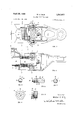
- FIGURE 1 is a plan view of a preferred embodiment of the releasing draft rigging of the present invention.
- FIGURE 2 is a side elevational view of the structure of FIGURE 1;
- FIGURE 3 is a fragmentary plan view on an enlarged scale of the structure of FIGURE 1 taken along lines 3-3 of FIGURE 4;
- FIGURE 4 is a vertical sectional view taken along lines 4- 1 of FIGURE 3;
- FIGURES 5, 6 and 7 are, respectively, outer end, side and inner end elevational views of one of the shear pins connecting parts of the structure of FIGURE 3;
- FIGURES 8 and 9 are, respectively, outer end and side elevational views, on the scale of FIGURES 5, 6 and 7, of the bushing for the pin of those figures.
- the illustrated draft rigging is comprised of an autom-atic subway-type coupler 1, such as illustrated in the copending application of Geoffrey W. Cope, Serial No. 283,395, filed May 27, 1963, now Patent No. 3,181,708, issued May 4, 1965, which is adapted to interlock against relative movement with a mating coupler.
- the coupler 1 is connected for relative vertical swinging to a yoke 2 by a horizontal pivot pin 3 and is yield ably held at coupling height by a spring-pressed plunger 4 depending from the yoke.
- a drawbar 5 pivoted at the rear for horizontal swinging to an anchor member 6 fixed to the underframe (not shown) of the subway or like car (not shown) and supported at the front on the usual radial carrier bar (not shown), which it receives in a slot 7, mounts the yoke 2.
- the illustrated drawbar 5 is formed intermediate its ends or longitudinal extremities as a housing 8 containing a pocket 9 open at top and bottom and bounded at side by laterially spaced side walls 10 and at front and rear by longitudinally spaced front and rear walls 11 and 12, respectively.
- the pocket 9 is closed at top and bottom toward the rear by cover or closure plates 13 welded or otherwise fixed to the drawbar.
- a rubber or other cushioning unit 14 housed or contained in the front part of the pocket 9 is a rubber or other cushioning unit 14- suitable for cushioning the draft and normal or ordinary buffing forces transmitted to it from coupler 1 through the yoke 2.
- the yoke 2 is slidably mounted in the housing 8 for relative longitudinal movement or telescoping in longitudinally spaced, preferably lined or bushed front and rear bearings 15 and 16, respectively.
- the front hearing 15 is fixed against relative movement to the drawbar 5 and may be rigid or, as illustrated, integral with the front wall 11 of the housing 8 and projects forwardly from the pocket 9.
- the rear bearing 16 may be rigid with the rear wall 12' and project rearward from the pocket 9, with a normally fixed intermediate backing or stop block as the backstop for the cushioning unit 14 under normal butting forces.
- the illustrated draft rigging dispenses with a separate rear bearing and uses as the rear bearing 16 a normally fixed bearing, backing or Stop block or member which also backstops the cushioning unit 14.
- the yoke 2 has a stem 17 which extends through the front and rear bearings 15 and 16 and the intervening cushioning unit 14.
- the yoke stem 17 has sliding in the front bearing 15 a cylindrical boss 18 and, rearwardly therefrom, is of reduced cross-section, with a cylindrical collar or sleeve 19 of the diameter of the boss bolted or otherwise releasably attached or secured to its rear end for sliding in the rear bearing 16.
- the illustrated bearing block 16 is of rectangular cross-section and flat-faced to conform to and engage the sides of that part of the pocket. So formed, the bearing block 16 under abnormal or extraordinary bufiing forces, such as experienced in a collision, can slide rearwardly on the bottom cover plate 13 with the yoke 2 and, by aperturing the rear wall 12, as at 21, to pass the collar 19, the rearward movement of the bearing block can continue until it abuts against and is stopped by the rear wall.
- the bearing block 16 normally is held, retained or secured against movement to the drawbar by a releasing connection that will release to permit rearward movement of the bearing block only under bufling forces that are abnormal or above a predetermined level.
- the releasing connection of this invention between the bearing block 16 and the drawbar 5 is a plurality of shear pin assemblies 22.
- the shear pin assemblies 22 Preferably four and arranged two at either side, the shear pin assemblies 22 have shear pins 23 that extend through the side walls of the drawbar 5 and into the confronting sides 24 of the bearing block 16.
- Each of the shear pins 23 has intermediate its ends a necked or reduced shear section 25 that aligns with or lies in the plane of the interface between a sidewall 10 and the confronting side 24 and the pin extends, perpendicular or normal to that interface, through an aperture 26 in the side wall and into a socket 27 in the confronting or adjoining side of the bearing block.
- the shear pin 23 is spaced radially therefrom by an exteriorly threaded bushing 28, the hex or like head 29 of which engages the exterior face 30 of the side wall 10 about the preferably reinforced aperture.
- the bushing 28 has an exteriorly threaded shank 31 that is threaded or screwed into and of substantially the depth of the aperture 26 and also is internally threaded, as at 32, at lease to the depth of its head 29.
- the shear pin 23 is externally threaded over a portion of its outer part 33, outwardly of the neck 25, for threading or screwing from within into the bushing 28.
- the inner part 36 of the shear pin 23 preferably is smooth and inwardly tapered or frusto-conical for a wedge fit with its correspondingly configured socket 27 in the bearing block 16.
- the preferred shear pin 23 has an axial drilling 37 extending through its inner part 36 and across the weakened or shear section or neck 25.
- each shear pin 23 is screwed from within into one of the bushings 28 and the latter is then screwed into its aperture 21 in the side wall 10 of the drawbar 5 until its head 29 is tight against the exterior face 30 of that wall.
- the shear pin 23, either as or after the insertion of the bushing into the aperture 26, is turned relative to the bushing until its inner, plug or wedge part 36 is tight in its socket 27 in the bearing block 16.
- the shear pins 23 can be locked against turning by looping a lock wire 39 through a radial drilling or hole 40 in the fiat tongue 38 of each pin and the companion pin on the same side.
- the shear pins 23 With the strength of each through its reduced shear or fracture section 25 predetermined such that all will shear or fracture simultaneously through that section on application of a predetermined abnormal buffing force to the bearing block 16, the shear pins 23 will hold the bearing block against movement in the pocket 9 in the drawbar 5 under draft and normal buffing forces and release the bearing block for rearward movement in the pocket under the predetermined abnormal bufiing force, thus protecting both the draft rigging and the underframe of the car from damage by the latter force by transferring it to the body of the car.
- a suitable turning tool (not shown) is used to unscrew the bushing 28 after cutting of the lock wire 39 and, as the bushing is unscrewed, it extracts with it the outer part 33 of the shear pin 23.
- the bearing block 16 is then shifted longitudinally as necessary to align the sockets 27'with the apertures 26 and, by a suitable extraction tool (not shown) inserted in the then exposed axial drilling 37 in the inner part 36 of the pin, that part is extracted or withdrawn from its socket. Thereafter, new shear pins are applied and the draft rigigng is ready for reuse.
- railway draft rigging comprising a housing having a pocket containing cushioning means, means in said pocket forwardly of a rear end thereof for backing said cushioning means under buffing forces, and releasing means normally connecting said backing means to said housing against rearward movement in said pocket, said releasing means including externally and internally threaded bushing means threaded into aperture means in said housing, and shear pin means threaded into said bushing means and extending therefrom into said backing means.
- railway draft rigging comprising a housing having a pocket containing cushioning means, means in said pocket forwardly of a rear end thereof for backing said cushioning means under buffing forces, and releasing means normally connecting said backing means to said housing against rearward movement in said pocket, said releasing means including a plurality of externally and internally threaded bushings each threaded into an aperture in a side wall of said pocket, and a shear pin threaded into each bushing and extending therefrom into a side of said backing means.
- Draft rigging comprising a housing having a pocket containing cushioning means, a backing member in said pocket forwardly of a rear wall thereof for backing said cushioning means under buffing forces, and releasing means normally connecting said backing member to said housing against rearward movement in said pocket, said releasing means including a plurality of externally and internally threaded bushings each threaded into an aperture in a side wall of said pocket, and a shear pin threaded into each bushing and extending therefrom into a side of said backing means.
- Draft rigging comprising a housing having a pocket containing cushioning means, a backing member slidably mounted in said pocket forwardly of a rear wall thereof for backing said cushioning means under butting forces,
- releasing means normally connecting said backing member to said housing against rearward movement in said pocket
- said releasing means including a plurality of 5.
- a drawbar having a pocket containing cushioning means, said yoke extending rearwardly into said pocket through said cushioning means and supported forwardly thereof in a front bearing fixed to said drawbar, a bearing member slidably mounted in said pocket forwardly of a rear wall thereof, said bearing member backing said cushioning means under buffing forces and being a rear bearing for said yoke, and releasing means normally connecting said bearing member to said drawbar against rearward movement in said pocket
- said releasing means including a plurality of externally and internally threaded bushings each threaded into an aperture in a side wall of said pocket, and a shear pin for each bushing having an outer part threading thereinto and an inner part socketed in a side of said bearing member.
- railway draft rigging comprising a housing having a pocket containing cushioning means, a backing member mounted in said pocket forwardly of a rear wall thereof for rearward movement therein and backing said cushioning means under buffing forces, and releasing means normally securing said backing member to said housing against rearward movement in said pocket, said releasing means including an externally and internally threaded headed bushing threaded from without into an aperture in a side wall of said pocket, and a shear pin having an outer part threaded from within into said bushing and an inner part socketed in a side of said backing member.
- railway draft rigging comprising a housing having a pocket containing cushioning means, a backing member mounted in said pocket forwardly of a rear wall thereof for rearward movement therein and backing said cushioning means under 'bufling forces, and releasing means normally securing said backing member to said housing against rearward movement in said pocket, 'said releasing means including an externally and internally threaded headed bushing threaded from without into an aperture in a side wall of said pocket, and a shear pin having an outer part threaded from within into said bushing and an inwardly tapered inner part wedged into a correspondingly tapered socket in a side of said backing member.
- railway draft rigging comprising a housing having a pocket containing cushioning means, a backing member mounted in said pocket forwardly of a rear wall thereof for rearward movement therein and backing said cushioning means under bufling forces, and releasing means normally securing said backing member to said housing against rearward movement in said pocket, said releasing means including an externally and internally threaded headed bushing threaded from without into an aperture in a side wall of said pocket, and a shear pin having an outer part threaded from Within into and'accessible for turning from without said bushing and an inwardly tapered inner part wedged into a correspondingly tapered socket in a side of said backing member.
- railway draft rigging comprising a housing having a pocket containing cushioning means, a backing member mounted in said pocket forwardly of a rear wall thereof for rearward movement therein and backing said cushioning means under bufiing forces, and releasing means normally securing said backing member to said housing against rearward movement in said pocket, said releasing means including a bushing having an internally threaded head and an externally threaded and internally smoothbored stern threaded from without into an aperture in a side wall of said pocket, and a shear pin having an outer part threaded over an outer portion and smooth-surfaced over an inner portion thereof, respectively, for threading into and slidingly fitting said head and bore of said bushings, said pin having an inwardly tapered smooth-surfaced inner part wedgeable into a correspondingly configured socket in said backing member and a shear section between said outer and inner parts.
- a shear pin assembly for normally connecting a pair of members against relative movement comprising an externally and internally threaded bushing threaded into an aperture in one of said members, and a shear pin threaded into said bushing and extending therefrom into the other member.
- railway draft rigging comprising a housing having a pocket containing cushioning means, a backing member mounted in said pocket forwardly of a rear wall thereof for rearward movement therein and backing said cushioning means under buffing forces, and releasing means normally securing said backing member to said housing against rearward movement in said pocket, said releasing means including an externally and internally threaded headed bushing threaded from without into an aperture in a side wall of said pocket, and a shear pin having an outer part threaded into said bushing and an inner part socketed in a side of said bearing member, and means in said inner part and exposed on shearing of said pin for enabling said inner part to be extracted through said aperture.
Description
April 26, 1966 w. c. DILG RAILWAY DRAFT RIGGING 2 Sheets-Sheet 1 Filed Jan. 14, 1965 uuu Inventor:
Walter C. Dilg Z.
his Attorney April 6, 1966 w. c. DILG 3,247,977
RAILWAY DRAFT RIGGING Filed Jan. 14, 1965 2 Sheets-Sheet 2,
FIG. 5 FIG. 7
1: F1G 9 Inventor:
Walter C. D119 hisAHorney United States Patent 3,247,977 RAILWAY DRAFT IRIGGING Walter C. Dilg, Glen Ellyn, Ill., assignor to Symington Wayne Corporation, Salisbury, Md, a corporation of Maryland Filed .Ian. 14, 1965, Ser. No. 425,529 11 Claims. (Cl. 213-9) This invention relates to railway draft rigging.
In subway and other railway cars, bufiing and draft forces between connected or coupled cars normally are transmitted to their underframes through draft gears or other suitable cushioning devices contained in their draft rigging. However, particularly in the case of subway cars, it is desirable that the draft riggings and underframes be protected from damage by abnormal bufi ing forces, such as experienced in collisions, by causing such forces to be transmitted directly between the bodies of the cars. This is accomplishable by providing one or each of the connected cars with a releasing draft rigging which, while enabling the bodies normally to be spaced by their couplers or other connecting means, will release under buffing forces above a predetermined level and, by telescoping of the connecting means into one or either car, produce direct contact between the adjoining ends of the bodies. I
The primary object of the present invention is to provide an improved releasing draft rigging which not only releases under abnormal bufiing forces but is readily restorable to its initial condition.
Another object of the invention is to provide in railway draft rigging wherein buffing forces are transmitted through a cushioning device to a movable member, an improved releasin-g connection between the member and its housing for enabling the member to move rearwardly under normal buffing forces.
An additional object of the invention is to provide an improved shear pin assembly which both normally locks the member it connects against relative movement and on being sheared is readily removable for replacement.
Other objects and advantages of the invention will appear hereinafter in detailed description, be particularly pointed out in the appended claims, and be illustrated in the accompanying drawings, in which:
FIGURE 1 is a plan view of a preferred embodiment of the releasing draft rigging of the present invention;-
FIGURE 2 is a side elevational view of the structure of FIGURE 1;
FIGURE 3 is a fragmentary plan view on an enlarged scale of the structure of FIGURE 1 taken along lines 3-3 of FIGURE 4;
FIGURE 4 is a vertical sectional view taken along lines 4- 1 of FIGURE 3;
FIGURES 5, 6 and 7 are, respectively, outer end, side and inner end elevational views of one of the shear pins connecting parts of the structure of FIGURE 3; and
FIGURES 8 and 9 are, respectively, outer end and side elevational views, on the scale of FIGURES 5, 6 and 7, of the bushing for the pin of those figures.
Referring now in detail to the drawings in which like reference characters designate like parts, the improved releasing draft rigging of the present invention, while otherwise usable, probably will find its principal use in subway and like cars. It, therefore, is draft rigging for such 1 a car that has been illustrated as exemplary of the invention.
The illustrated draft rigging is comprised of an autom-atic subway-type coupler 1, such as illustrated in the copending application of Geoffrey W. Cope, Serial No. 283,395, filed May 27, 1963, now Patent No. 3,181,708, issued May 4, 1965, which is adapted to interlock against relative movement with a mating coupler. The coupler 1 is connected for relative vertical swinging to a yoke 2 by a horizontal pivot pin 3 and is yield ably held at coupling height by a spring-pressed plunger 4 depending from the yoke. A drawbar 5, pivoted at the rear for horizontal swinging to an anchor member 6 fixed to the underframe (not shown) of the subway or like car (not shown) and supported at the front on the usual radial carrier bar (not shown), which it receives in a slot 7, mounts the yoke 2.
Conveniently cast, the illustrated drawbar 5 is formed intermediate its ends or longitudinal extremities as a housing 8 containing a pocket 9 open at top and bottom and bounded at side by laterially spaced side walls 10 and at front and rear by longitudinally spaced front and rear walls 11 and 12, respectively. Substantially rectangular in horizontal cross-section, the pocket 9 is closed at top and bottom toward the rear by cover or closure plates 13 welded or otherwise fixed to the drawbar. Housed or contained in the front part of the pocket 9 is a rubber or other cushioning unit 14- suitable for cushioning the draft and normal or ordinary buffing forces transmitted to it from coupler 1 through the yoke 2.
The yoke 2 is slidably mounted in the housing 8 for relative longitudinal movement or telescoping in longitudinally spaced, preferably lined or bushed front and rear bearings 15 and 16, respectively. The front hearing 15 is fixed against relative movement to the drawbar 5 and may be rigid or, as illustrated, integral with the front wall 11 of the housing 8 and projects forwardly from the pocket 9. In the manner illustrated in my copending application, the rear bearing 16 may be rigid with the rear wall 12' and project rearward from the pocket 9, with a normally fixed intermediate backing or stop block as the backstop for the cushioning unit 14 under normal butting forces. However, to shorten the length of the drawbar 5, the illustrated draft rigging dispenses with a separate rear bearing and uses as the rear bearing 16 a normally fixed bearing, backing or Stop block or member which also backstops the cushioning unit 14. The yoke 2 has a stem 17 which extends through the front and rear bearings 15 and 16 and the intervening cushioning unit 14. For stability, without curtailment of the effective area of the illustrated rubber cushioning unit 14, the yoke stem 17 has sliding in the front bearing 15 a cylindrical boss 18 and, rearwardly therefrom, is of reduced cross-section, with a cylindrical collar or sleeve 19 of the diameter of the boss bolted or otherwise releasably attached or secured to its rear end for sliding in the rear bearing 16. Mounted on a cylindrical neck 20 on the stem 17 concentric with but of less cross-section than the boss 18 and collar 19, the cushioning unit 14 is compressed in draft between the collar and the front wall 11 and in buff between the boss and bearing block on rear bearing 16.
Contained in the rear part of the pocket 9 closed at top and bottom by the cover plates 13, normally longitudinally between and spaced from the front and rear walls 11 and 12, the illustrated bearing block 16 is of rectangular cross-section and flat-faced to conform to and engage the sides of that part of the pocket. So formed, the bearing block 16 under abnormal or extraordinary bufiing forces, such as experienced in a collision, can slide rearwardly on the bottom cover plate 13 with the yoke 2 and, by aperturing the rear wall 12, as at 21, to pass the collar 19, the rearward movement of the bearing block can continue until it abuts against and is stopped by the rear wall. It is the addition of this increment to the telescoping or rearward travel of the yoke 2 into the drawbar 5 normally permitted by the compressibility of the cushioning unit 14, that is responsiblefor relieving the draft riggings and underframes of connected cars from abnormal buffing forces and transmitting them instead directly between the car bodies (not shown), usually through anti-climbers at their adjoining ends, such as shown in Larsson Patent No. 2,802,581, issued Aug. 13, 1957. Since the cushioning device 14 would serve no purpose, at least in buff, were the car bodies permitted to contact under normal bufling forces, the bearing block 16 normally is held, retained or secured against movement to the drawbar by a releasing connection that will release to permit rearward movement of the bearing block only under bufling forces that are abnormal or above a predetermined level.
The releasing connection of this invention between the bearing block 16 and the drawbar 5 is a plurality of shear pin assemblies 22. Preferably four and arranged two at either side, the shear pin assemblies 22 have shear pins 23 that extend through the side walls of the drawbar 5 and into the confronting sides 24 of the bearing block 16. Each of the shear pins 23 has intermediate its ends a necked or reduced shear section 25 that aligns with or lies in the plane of the interface between a sidewall 10 and the confronting side 24 and the pin extends, perpendicular or normal to that interface, through an aperture 26 in the side wall and into a socket 27 in the confronting or adjoining side of the bearing block. Instead of directly engaging the side of.the aperture 26, the shear pin 23 is spaced radially therefrom by an exteriorly threaded bushing 28, the hex or like head 29 of which engages the exterior face 30 of the side wall 10 about the preferably reinforced aperture. The bushing 28 has an exteriorly threaded shank 31 that is threaded or screwed into and of substantially the depth of the aperture 26 and also is internally threaded, as at 32, at lease to the depth of its head 29. In turn, the shear pin 23 is externally threaded over a portion of its outer part 33, outwardly of the neck 25, for threading or screwing from within into the bushing 28.
To minimize lateral play between the shear pin 23 and the bushing 28, the external threading of the outer part 33 of the shear pin 23, while extending outwardly to the outer end of that part, preferably terminates inwardly short of the shear section or annular notch 25 to provide therebetween a smooth-surfaced cylindrical inner portion 34 having a sliding fit with the preferably correspondingly smooth cylindrical bore 35 of the shank 31 of the bushing 28. For the same purpose, the inner part 36 of the shear pin 23 preferably is smooth and inwardly tapered or frusto-conical for a wedge fit with its correspondingly configured socket 27 in the bearing block 16. For a different purpose, hereafter to be explained, the preferred shear pin 23 has an axial drilling 37 extending through its inner part 36 and across the weakened or shear section or neck 25.
Flat-tongued, as at 38, or otherwise suitably configured at its outer end to take or receive a turning tool (not shown), each shear pin 23 is screwed from within into one of the bushings 28 and the latter is then screwed into its aperture 21 in the side wall 10 of the drawbar 5 until its head 29 is tight against the exterior face 30 of that wall. Accessible exteriorly or from without for turning relative to the bushing 28 and preferably extending therethrough, the shear pin 23, either as or after the insertion of the bushing into the aperture 26, is turned relative to the bushing until its inner, plug or wedge part 36 is tight in its socket 27 in the bearing block 16. Then effectively locking the bearing block 16 against longitudinal movement relative to the drawbar 5, the shear pins 23 can be locked against turning by looping a lock wire 39 through a radial drilling or hole 40 in the fiat tongue 38 of each pin and the companion pin on the same side. With the strength of each through its reduced shear or fracture section 25 predetermined such that all will shear or fracture simultaneously through that section on application of a predetermined abnormal buffing force to the bearing block 16, the shear pins 23 will hold the bearing block against movement in the pocket 9 in the drawbar 5 under draft and normal buffing forces and release the bearing block for rearward movement in the pocket under the predetermined abnormal bufiing force, thus protecting both the draft rigging and the underframe of the car from damage by the latter force by transferring it to the body of the car.
Removal of a shear pin 23 for replacement after shearing is quite simple. A suitable turning tool (not shown) is used to unscrew the bushing 28 after cutting of the lock wire 39 and, as the bushing is unscrewed, it extracts with it the outer part 33 of the shear pin 23. The bearing block 16 is then shifted longitudinally as necessary to align the sockets 27'with the apertures 26 and, by a suitable extraction tool (not shown) inserted in the then exposed axial drilling 37 in the inner part 36 of the pin, that part is extracted or withdrawn from its socket. Thereafter, new shear pins are applied and the draft rigigng is ready for reuse.
From the above detailed description it will be apparent that there has been provided an improved releasing draft rigging which not only will release for protecting itself and the underframe from abnormal buffing forces but is readily restorable to initial condition. It should be understood that the described and disclosed embodiment is merely exemplary of the invention and that all modifications are intended to be included that do not depart from the spirit of the invention and the scope of the appended claims.
Having described my invention, I claim:
1. Railway draft rigging comprising a housing having a pocket containing cushioning means, means in said pocket forwardly of a rear end thereof for backing said cushioning means under buffing forces, and releasing means normally connecting said backing means to said housing against rearward movement in said pocket, said releasing means including externally and internally threaded bushing means threaded into aperture means in said housing, and shear pin means threaded into said bushing means and extending therefrom into said backing means.
2. Railway draft rigging comprising a housing having a pocket containing cushioning means, means in said pocket forwardly of a rear end thereof for backing said cushioning means under buffing forces, and releasing means normally connecting said backing means to said housing against rearward movement in said pocket, said releasing means including a plurality of externally and internally threaded bushings each threaded into an aperture in a side wall of said pocket, and a shear pin threaded into each bushing and extending therefrom into a side of said backing means.
3. Draft rigging comprising a housing having a pocket containing cushioning means, a backing member in said pocket forwardly of a rear wall thereof for backing said cushioning means under buffing forces, and releasing means normally connecting said backing member to said housing against rearward movement in said pocket, said releasing means including a plurality of externally and internally threaded bushings each threaded into an aperture in a side wall of said pocket, and a shear pin threaded into each bushing and extending therefrom into a side of said backing means.
4. Draft rigging comprising a housing having a pocket containing cushioning means, a backing member slidably mounted in said pocket forwardly of a rear wall thereof for backing said cushioning means under butting forces,
and releasing means normally connecting said backing member to said housing against rearward movement in said pocket, said releasing means including a plurality of 5. In draft rigging including a yoke and a coupler pivotally connected thereto, the improvement comprising a drawbar having a pocket containing cushioning means, said yoke extending rearwardly into said pocket through said cushioning means and supported forwardly thereof in a front bearing fixed to said drawbar, a bearing member slidably mounted in said pocket forwardly of a rear wall thereof, said bearing member backing said cushioning means under buffing forces and being a rear bearing for said yoke, and releasing means normally connecting said bearing member to said drawbar against rearward movement in said pocket, said releasing means including a plurality of externally and internally threaded bushings each threaded into an aperture in a side wall of said pocket, and a shear pin for each bushing having an outer part threading thereinto and an inner part socketed in a side of said bearing member.
6. Railway draft rigging comprising a housing having a pocket containing cushioning means, a backing member mounted in said pocket forwardly of a rear wall thereof for rearward movement therein and backing said cushioning means under buffing forces, and releasing means normally securing said backing member to said housing against rearward movement in said pocket, said releasing means including an externally and internally threaded headed bushing threaded from without into an aperture in a side wall of said pocket, and a shear pin having an outer part threaded from within into said bushing and an inner part socketed in a side of said backing member.
7. Railway draft rigging comprising a housing having a pocket containing cushioning means, a backing member mounted in said pocket forwardly of a rear wall thereof for rearward movement therein and backing said cushioning means under 'bufling forces, and releasing means normally securing said backing member to said housing against rearward movement in said pocket, 'said releasing means including an externally and internally threaded headed bushing threaded from without into an aperture in a side wall of said pocket, and a shear pin having an outer part threaded from within into said bushing and an inwardly tapered inner part wedged into a correspondingly tapered socket in a side of said backing member.
8. Railway draft rigging comprising a housing having a pocket containing cushioning means, a backing member mounted in said pocket forwardly of a rear wall thereof for rearward movement therein and backing said cushioning means under bufling forces, and releasing means normally securing said backing member to said housing against rearward movement in said pocket, said releasing means including an externally and internally threaded headed bushing threaded from without into an aperture in a side wall of said pocket, and a shear pin having an outer part threaded from Within into and'accessible for turning from without said bushing and an inwardly tapered inner part wedged into a correspondingly tapered socket in a side of said backing member.
9. Railway draft rigging comprising a housing having a pocket containing cushioning means, a backing member mounted in said pocket forwardly of a rear wall thereof for rearward movement therein and backing said cushioning means under bufiing forces, and releasing means normally securing said backing member to said housing against rearward movement in said pocket, said releasing means including a bushing having an internally threaded head and an externally threaded and internally smoothbored stern threaded from without into an aperture in a side wall of said pocket, and a shear pin having an outer part threaded over an outer portion and smooth-surfaced over an inner portion thereof, respectively, for threading into and slidingly fitting said head and bore of said bushings, said pin having an inwardly tapered smooth-surfaced inner part wedgeable into a correspondingly configured socket in said backing member and a shear section between said outer and inner parts.
It). A shear pin assembly for normally connecting a pair of members against relative movement comprising an externally and internally threaded bushing threaded into an aperture in one of said members, and a shear pin threaded into said bushing and extending therefrom into the other member.
11. Railway draft rigging comprising a housing having a pocket containing cushioning means, a backing member mounted in said pocket forwardly of a rear wall thereof for rearward movement therein and backing said cushioning means under buffing forces, and releasing means normally securing said backing member to said housing against rearward movement in said pocket, said releasing means including an externally and internally threaded headed bushing threaded from without into an aperture in a side wall of said pocket, and a shear pin having an outer part threaded into said bushing and an inner part socketed in a side of said bearing member, and means in said inner part and exposed on shearing of said pin for enabling said inner part to be extracted through said aperture.
References Cited by the Examiner UNITED STATES PATENTS 2,508,285 5/1950 Otis et al 294-86.l8 2,802,580 8/1957 Larsson 2l3-45 2,802,581 8/1957 Lars-son 2l345 ARTHUR is. LA POINT, Primary Examiner.
Claims (1)
- 9. RAILWAY DRAFT RIGGING COMPRISING A HOUSING HAVING A POCKET CONTAINING CUSHIONING MEANS, A BACKING MEMBER MOUNTED IN SAID POCKET FORWARDLY OF A REAR WALL THEREOF FOR REARWARD MOVEMENT THEREIN AND BACKING SAID CUSHIONING MEANS UNDER BUFFING FORCES, AND RELEASING MEANS NORMALLY SECURING SAID BACKING MEMBER TO SAID HOUSING AGAINST REARWARD MOVEMENT IN SAID POCKET, SAID RELEASING MEANS INCLUDING A BUSHING HAVING AN INTERNALLY THREADED HEAD AND AN EXTERNALLY THREADED AN INTERNALLY SMOOTHBORED STEM THREADED FROM WITHOUT INTO AN APERTURE IN A SIDE WALL OF SAID POCKET, AND A SHEAR PIN HAVING AN OUTER PART THREADED OVER AN OUTER PORTION AND SMOOTH-SURFACED OVER AN INNER PORTION THEREOF, RESPECTIVELY, FOR THREADING INTO AND SLIDINGLY FITTING SAID HEAD AND BORE OF SAID BUSHINGS, SAID PIN HAVING AN INWARDLY TAPERED SMOOTH-SURFACED INNER PART WEDGEABLE INTO A CORRESPONDINGLY CONFIGURED SOCKET IN SAID BACKING MEMBER AND A SHEAR SECTION BETWEEN SAID OUTER AND INNER PARTS.
Priority Applications (1)
| Application Number | Priority Date | Filing Date | Title |
|---|---|---|---|
| US425529A US3247977A (en) | 1965-01-14 | 1965-01-14 | Railway draft rigging |
Applications Claiming Priority (1)
| Application Number | Priority Date | Filing Date | Title |
|---|---|---|---|
| US425529A US3247977A (en) | 1965-01-14 | 1965-01-14 | Railway draft rigging |
Publications (1)
| Publication Number | Publication Date |
|---|---|
| US3247977A true US3247977A (en) | 1966-04-26 |
Family
ID=23686956
Family Applications (1)
| Application Number | Title | Priority Date | Filing Date |
|---|---|---|---|
| US425529A Expired - Lifetime US3247977A (en) | 1965-01-14 | 1965-01-14 | Railway draft rigging |
Country Status (1)
| Country | Link |
|---|---|
| US (1) | US3247977A (en) |
Cited By (5)
| Publication number | Priority date | Publication date | Assignee | Title |
|---|---|---|---|---|
| US4576294A (en) * | 1982-08-03 | 1986-03-18 | Scharfenbergkupplung Gmbh | Vehicle coupler device having means for taking excess impacts |
| EP1112909A1 (en) * | 1999-12-30 | 2001-07-04 | Westinghouse Air Brake Company | Coupler with extended emergency release and towing feature |
| EP1504978A1 (en) * | 2003-08-08 | 2005-02-09 | Westinghouse Air Brake Technologies Corporation | Emergency release shear mechanism for a railway drawbar |
| US10464381B2 (en) | 2017-01-20 | 2019-11-05 | Dellner Couplers Ab | Vehicle coupling device |
| US10967886B2 (en) * | 2018-10-05 | 2021-04-06 | Bombardier Transportation Gmbh | Draft sill using a tension cable |
Citations (3)
| Publication number | Priority date | Publication date | Assignee | Title |
|---|---|---|---|---|
| US2508285A (en) * | 1945-04-28 | 1950-05-16 | Herbert C Otis | Well tool |
| US2802581A (en) * | 1955-07-11 | 1957-08-13 | Ohio Brass Co | Automatic coupler with release |
| US2802580A (en) * | 1953-01-16 | 1957-08-13 | Ohio Brass Co | Car couplers |
-
1965
- 1965-01-14 US US425529A patent/US3247977A/en not_active Expired - Lifetime
Patent Citations (3)
| Publication number | Priority date | Publication date | Assignee | Title |
|---|---|---|---|---|
| US2508285A (en) * | 1945-04-28 | 1950-05-16 | Herbert C Otis | Well tool |
| US2802580A (en) * | 1953-01-16 | 1957-08-13 | Ohio Brass Co | Car couplers |
| US2802581A (en) * | 1955-07-11 | 1957-08-13 | Ohio Brass Co | Automatic coupler with release |
Cited By (8)
| Publication number | Priority date | Publication date | Assignee | Title |
|---|---|---|---|---|
| US4576294A (en) * | 1982-08-03 | 1986-03-18 | Scharfenbergkupplung Gmbh | Vehicle coupler device having means for taking excess impacts |
| EP1112909A1 (en) * | 1999-12-30 | 2001-07-04 | Westinghouse Air Brake Company | Coupler with extended emergency release and towing feature |
| AU759111B2 (en) * | 1999-12-30 | 2003-04-03 | Westinghouse Air Brake Company | Coupler with extended emergency release and towing feature |
| EP1504978A1 (en) * | 2003-08-08 | 2005-02-09 | Westinghouse Air Brake Technologies Corporation | Emergency release shear mechanism for a railway drawbar |
| US20050029215A1 (en) * | 2003-08-08 | 2005-02-10 | Grau Curtiss A. | High capacity shear mechanism |
| US6981599B2 (en) * | 2003-08-08 | 2006-01-03 | Westinghouse Air Brake Technologies Corporation | High capacity shear mechanism |
| US10464381B2 (en) | 2017-01-20 | 2019-11-05 | Dellner Couplers Ab | Vehicle coupling device |
| US10967886B2 (en) * | 2018-10-05 | 2021-04-06 | Bombardier Transportation Gmbh | Draft sill using a tension cable |
Similar Documents
| Publication | Publication Date | Title |
|---|---|---|
| US5035338A (en) | Slackless railcar connections with extractable wedge | |
| US2282146A (en) | Draft gear mechanism for railway vehicles | |
| US3247977A (en) | Railway draft rigging | |
| US4064998A (en) | Railway coupler and draft rigging | |
| US3515288A (en) | Draft apparatus with tension-breakable emergency release means | |
| US2635766A (en) | Railway draft gear cushioning mechanism | |
| US2802581A (en) | Automatic coupler with release | |
| US2212843A (en) | Draft rigging | |
| US3197037A (en) | Railway coupler aligning apparatus | |
| US4022329A (en) | Draft rigging for railway cars | |
| US5097973A (en) | Railcar articulated connector and wedge shim therefore | |
| US2019311A (en) | Draft gear | |
| US2990963A (en) | Rotary coupler arrangement | |
| US6499613B1 (en) | Coupler with extended emergency release and towing feature | |
| US6321922B1 (en) | Coupling shock resistant (csr) coupler | |
| US3856153A (en) | Coupler yoke with draft gear removal means | |
| US5139159A (en) | Connecting pin for articulated coupling arrangement | |
| US2363197A (en) | Railroad car draft gear and buffer stem mounting | |
| US2576214A (en) | Shock absorbing mechanism for railway draft riggings | |
| US2929518A (en) | Draft gear | |
| US2125326A (en) | Engine-tender buffer mechanism | |
| US2403583A (en) | Railway draft rigging | |
| US1361087A (en) | Draft-rigging construction | |
| US5092204A (en) | Apparatus for aligning spherical member during assembly of an articulated coupling system | |
| US1871423A (en) | Railway draft rigging |