US3221867A - Chain conveyor - Google Patents
Chain conveyor Download PDFInfo
- Publication number
- US3221867A US3221867A US307173A US30717363A US3221867A US 3221867 A US3221867 A US 3221867A US 307173 A US307173 A US 307173A US 30717363 A US30717363 A US 30717363A US 3221867 A US3221867 A US 3221867A
- Authority
- US
- United States
- Prior art keywords
- chain
- articles
- store
- transport chain
- conveyor
- Prior art date
- Legal status (The legal status is an assumption and is not a legal conclusion. Google has not performed a legal analysis and makes no representation as to the accuracy of the status listed.)
- Expired - Lifetime
Links
Images


Classifications
-
- B—PERFORMING OPERATIONS; TRANSPORTING
- B65—CONVEYING; PACKING; STORING; HANDLING THIN OR FILAMENTARY MATERIAL
- B65G—TRANSPORT OR STORAGE DEVICES, e.g. CONVEYORS FOR LOADING OR TIPPING, SHOP CONVEYOR SYSTEMS OR PNEUMATIC TUBE CONVEYORS
- B65G47/00—Article or material-handling devices associated with conveyors; Methods employing such devices
- B65G47/22—Devices influencing the relative position or the attitude of articles during transit by conveyors
- B65G47/26—Devices influencing the relative position or the attitude of articles during transit by conveyors arranging the articles, e.g. varying spacing between individual articles
- B65G47/261—Accumulating articles
- B65G47/268—Accumulating articles by means of belt or chain conveyor
-
- B—PERFORMING OPERATIONS; TRANSPORTING
- B65—CONVEYING; PACKING; STORING; HANDLING THIN OR FILAMENTARY MATERIAL
- B65G—TRANSPORT OR STORAGE DEVICES, e.g. CONVEYORS FOR LOADING OR TIPPING, SHOP CONVEYOR SYSTEMS OR PNEUMATIC TUBE CONVEYORS
- B65G17/00—Conveyors having an endless traction element, e.g. a chain, transmitting movement to a continuous or substantially-continuous load-carrying surface or to a series of individual load-carriers; Endless-chain conveyors in which the chains form the load-carrying surface
- B65G17/30—Details; Auxiliary devices
- B65G17/38—Chains or like traction elements; Connections between traction elements and load-carriers
- B65G17/40—Chains acting as load-carriers
-
- B—PERFORMING OPERATIONS; TRANSPORTING
- B65—CONVEYING; PACKING; STORING; HANDLING THIN OR FILAMENTARY MATERIAL
- B65G—TRANSPORT OR STORAGE DEVICES, e.g. CONVEYORS FOR LOADING OR TIPPING, SHOP CONVEYOR SYSTEMS OR PNEUMATIC TUBE CONVEYORS
- B65G2201/00—Indexing codes relating to handling devices, e.g. conveyors, characterised by the type of product or load being conveyed or handled
- B65G2201/02—Articles
Definitions
- the invention relates to a chain conveyor on which the articles being conveyed can be temporarily stored while the conveyor is still moving.
- the chain conveyor of the invention comprises at least one endless chain arranged for continual operation, and is characterized in that movable means in the form of endless smaller chains, so-called store chains, are mounted on the transport chain, said store chains being arranged to support the articles being conveyed so that said articles can bemoved relative to the conveyor in its longitudinal direction, a stopping member being provided above the conveyor so that it can be placed in the way of the articles being conveyed, the articles when thus stopped being collected at the stopping member while the transport chain continues moving.
- the movable means in the form of endless smaller chains will hereinbelow be referred to as store chains.
- At least one store chain is arranged between each pair of adjacent axles connecting the links of the transport chain.
- the upper portions of all store chains are situated in one plane. As the store chains overlap each other the upper surface of the transport chain consists entirely of a store chain. Therefore, articles of any shape can be transported on the chain conveyor.
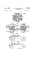
- FIG. 1 shows an elevation of a chain conveyor according to the invention.
- FIGS. 2 and 3 show an embodiment of a transport chain with store chains, FIG. 2 showing the transport chain from above and FIG. 3 illustrating a section through line III-III in FIG. 2.
- FIGS. 4 and 5 illustrate two alternative Ways of mounting the store chains on a transport chain of the type shown in FIGS. 2 and 3.
- FIGS. 6 and 7 show another embodiment of a transport chain with store chains, FIG. 6 illustrating the transport chain from above and FIG. 7 illustrating a section through line VII VII in FIG. 6.
- the device of FIG. 1 consists of two chain wheels 1 and 2. supporting an endless transport chain consisting of links 3 interconnected by axles 4.
- Store chains 5 are provided along the entire length of the transport chain, said store chains being mounted on the transport chain in a way described below, for instance.
- a stopping member consisting of a plate 6 mounted on a horizontal pivot 7 and movable up and down by a hydraulic or pneumatic cylinder 8.
- Iron articles 912 having T-profiles are being transported on the conveyor.
- the articles are placed upon the conveyor with a mutual distance equal to the distance between articles 11 and 12. If it is desired to stop temporarily the unloading of articles from the conveyor the stop plate 6 is lowered into the illustrated position while the transport chain is allowed to continue its movement in the direction of the arrow.
- the store chains passing temporarily below profiles 9-11 will be moved relative to the transport chain so that their upper portions will be stationary relative to the articles 9-11. Consequently, there will be no friction between the articles and the transport chain.
- each transport chain is suflicient.
- This chain can be designed to have any desired width, and each link of said chain can be designed to support two or more store chains side by side.
- the transport chain shown in FIGS. 2 and 3 consists of links 13 and 14, interconnected by axles 15. Rollers 16 are pivoted on the ends of these axles and arranged to roll on supports 17 mounted below the upper portion of the transport chain and, if desired, also below the lower portion of the transport chain. Chain wheels 18-21 are pivoted on the axles 15, between the links. These chain wheels support store chains 2224 so that each store chain extends along one link, i.e., the store chain is mounted on two chain wheels belonging to two adjacent axles 15.
- FIG. 4 shows two chain wheels 25 and 26 which are mounted on a transport chain and which support a store chain 27.
- a support 28 is provided below the upper portion of the store chain and is fastened to one or both of the links of the transport chain. The support prevents the upper portion of the store chain from being bent down by the articles being conveyed.
- Rollers 29 are mounted on the axles of the store chain, for preventing friction between the store chain and the support.
- auxiliary links 30 are mounted between the axles 31 and 32 of the transport chain, parallel with the main links of the transport chain.
- the auxiliary link supports a store chain 44.
- the axles of said store chain are provided with rollers 33 engaging the auxiliary link.
- the transport chain of FIGS. 6 and 7 consist of links 3436 interconnected by axles 43 extending through the thickened end portions of the links. Two adjacent axles are connected by one link only. The ends of the axles are provided with rollers 37 arranged to roll on stationary supports 38.
- the links 34-36 also act as supports for store chains 39-41, one store chain being mounted on each link, in the same way as the store chains 32 are mounted on the auxiliary links 30 in the embodiment of FIG. 5.
- the axles of the store chains of FIGS. 6 and 7 are provided with rollers 42 designed to roll on the links for preventing friction, as also described with reference to FIG. 5.
- Chain conveyor comprising at least one endless transport chain arranged for continual operation, characterized in that movable means in the form of endless smaller chains, so-called store chains, are mounted on the transport chain, said store chains being arranged to support the articles being conveyed so that said articles can be moved relative to the conveyor in its longitudinal direction, a stopping member being provided above the conveyor so that it can be placed in the way of the articles being conveyed, the articles when thus stopped being collected at the stopping member while the transport chain continues moving.
- Chain conveyor as defined in claim 1 in which said endless transport chain consists of links connected by adjacent axles and in which one of said store chains is provided between each pair of said adjacent axles.
- Chain conveyor as defined in claim 1 in which said endless transport chain consists of links connected by adjacent axles and in which auxiliary links extend between and are mounted on said adjacent axles and in which one of said store chains is provided between each pair of adjacent axles, said store chains being supported by said auxiliary links.
Landscapes
- Engineering & Computer Science (AREA)
- Mechanical Engineering (AREA)
- Chain Conveyers (AREA)
Description
Dec. 7, 965 c. G. B. BERGLING ETAL 3,221,867
CHAIN CONVEYOR Filed Sept. 6, 1963 3 Sheets-Sheet 1 Fig 1 7 D 7, 1965 c. cs. B. BERGLING ETAL 3,221,367
CHAIN CONVEYOR 5 Sheets-Sheet 2 Filed Sept. 6, 1963 Dec. 7, 1965 c. G. B. BERGLING ETAL 3,221,867
I CHAIN CONVEYOR Filed Sept. 6, 1963 5 Sheets-Sheet 5 United States Patent 3,221,867 CHAIN CGNVEYOR Charles Gunnar Birger Bergling and Herman Nils Levin,
()rebro, Sweden, assignors to Ingenjorsfirma Hebe Aktiebolag, Orebro, Sweden, :1 company of Sweden Filed Sept. 6, 1963, Ser. No. 307,173 Claims priority, application Sweden, Sept. 7, 1962, 9,702/ 62 3 Claims. ((11. 198183) The invention relates to a chain conveyor on which the articles being conveyed can be temporarily stored while the conveyor is still moving. The chain conveyor of the invention comprises at least one endless chain arranged for continual operation, and is characterized in that movable means in the form of endless smaller chains, so-called store chains, are mounted on the transport chain, said store chains being arranged to support the articles being conveyed so that said articles can bemoved relative to the conveyor in its longitudinal direction, a stopping member being provided above the conveyor so that it can be placed in the way of the articles being conveyed, the articles when thus stopped being collected at the stopping member while the transport chain continues moving.
The movable means in the form of endless smaller chains will hereinbelow be referred to as store chains. At least one store chain is arranged between each pair of adjacent axles connecting the links of the transport chain. The upper portions of all store chains are situated in one plane. As the store chains overlap each other the upper surface of the transport chain consists entirely of a store chain. Therefore, articles of any shape can be transported on the chain conveyor.
The invention will be explained hereinbelow with reference to the accompanying drawings. FIG. 1 shows an elevation of a chain conveyor according to the invention. FIGS. 2 and 3 show an embodiment of a transport chain with store chains, FIG. 2 showing the transport chain from above and FIG. 3 illustrating a section through line III-III in FIG. 2. FIGS. 4 and 5 illustrate two alternative Ways of mounting the store chains on a transport chain of the type shown in FIGS. 2 and 3. FIGS. 6 and 7 show another embodiment of a transport chain with store chains, FIG. 6 illustrating the transport chain from above and FIG. 7 illustrating a section through line VII VII in FIG. 6.
The device of FIG. 1 consists of two chain wheels 1 and 2. supporting an endless transport chain consisting of links 3 interconnected by axles 4. Store chains 5 are provided along the entire length of the transport chain, said store chains being mounted on the transport chain in a way described below, for instance. Above the transport chain there is provided a stopping member consisting of a plate 6 mounted on a horizontal pivot 7 and movable up and down by a hydraulic or pneumatic cylinder 8.
Iron articles 912 having T-profiles are being transported on the conveyor. The articles are placed upon the conveyor with a mutual distance equal to the distance between articles 11 and 12. If it is desired to stop temporarily the unloading of articles from the conveyor the stop plate 6 is lowered into the illustrated position while the transport chain is allowed to continue its movement in the direction of the arrow. The articles having been stopped by the stopping member pack on the transport chain as illustrated by profiles 9-11. The store chains passing temporarily below profiles 9-11 will be moved relative to the transport chain so that their upper portions will be stationary relative to the articles 9-11. Consequently, there will be no friction between the articles and the transport chain.
For conveying small articles one transport chain is suflicient. This chain can be designed to have any desired width, and each link of said chain can be designed to support two or more store chains side by side. When conveying elongated articles, such as the illustrated articles, it is preferred to arrange two or more synchronously operated transport chains side by side at the desired distance.
The transport chain shown in FIGS. 2 and 3 consists of links 13 and 14, interconnected by axles 15. Rollers 16 are pivoted on the ends of these axles and arranged to roll on supports 17 mounted below the upper portion of the transport chain and, if desired, also below the lower portion of the transport chain. Chain wheels 18-21 are pivoted on the axles 15, between the links. These chain wheels support store chains 2224 so that each store chain extends along one link, i.e., the store chain is mounted on two chain wheels belonging to two adjacent axles 15.
FIG. 4 shows two chain wheels 25 and 26 which are mounted on a transport chain and which support a store chain 27. A support 28 is provided below the upper portion of the store chain and is fastened to one or both of the links of the transport chain. The support prevents the upper portion of the store chain from being bent down by the articles being conveyed. Rollers 29 are mounted on the axles of the store chain, for preventing friction between the store chain and the support.
As shown in FIG. 5 separate auxiliary links 30 are mounted between the axles 31 and 32 of the transport chain, parallel with the main links of the transport chain. The auxiliary link supports a store chain 44. The axles of said store chain are provided with rollers 33 engaging the auxiliary link.
The transport chain of FIGS. 6 and 7 consist of links 3436 interconnected by axles 43 extending through the thickened end portions of the links. Two adjacent axles are connected by one link only. The ends of the axles are provided with rollers 37 arranged to roll on stationary supports 38. The links 34-36 also act as supports for store chains 39-41, one store chain being mounted on each link, in the same way as the store chains 32 are mounted on the auxiliary links 30 in the embodiment of FIG. 5. The axles of the store chains of FIGS. 6 and 7 are provided with rollers 42 designed to roll on the links for preventing friction, as also described with reference to FIG. 5.
What is claimed is:
1. Chain conveyor, comprising at least one endless transport chain arranged for continual operation, characterized in that movable means in the form of endless smaller chains, so-called store chains, are mounted on the transport chain, said store chains being arranged to support the articles being conveyed so that said articles can be moved relative to the conveyor in its longitudinal direction, a stopping member being provided above the conveyor so that it can be placed in the way of the articles being conveyed, the articles when thus stopped being collected at the stopping member while the transport chain continues moving.
2. Chain conveyor as defined in claim 1 in which said endless transport chain consists of links connected by adjacent axles and in which one of said store chains is provided between each pair of said adjacent axles.
3. Chain conveyor as defined in claim 1 in which said endless transport chain consists of links connected by adjacent axles and in which auxiliary links extend between and are mounted on said adjacent axles and in which one of said store chains is provided between each pair of adjacent axles, said store chains being supported by said auxiliary links.
References Cited by the Examiner UNITED STATES PATENTS 2,154,844 4/1939 Harker et al 198183 2,257,230 9/1941 Drake 198183 2,829,762 4/1958 Oswald 198183 10 SAMUEL F. COLEMAN; Primary Examiner.
Claims (1)
1. CHAIN CONVEYOR, COMPRISING AT LEAST ONE ENDLESS TRANSPORT CHAIN ARRANGED FOR CONTINUAL OPERATION, CHARACTERIZED IN THAT MOVABLE MEANS IN THE FORM OF ENDLESS SMALLER CHAINS, SO-CALLED STORE CHAINS, ARE MOUNTED ON THE TRANSPORT CHAIN, SAID STORE CHAINS BEING ARRANGED TO SUPPORT THE ARTICLES BEING CONVEYED SO THAT SAID ARTICLES CAN BE MOVED RELATIVE TO THE CONVEYOR IN ITS LONGITUDINAL DIRECTION, A STOPPING MEMBER BEING PROVIDED ABOVE THE CONVEYOR SO THAT IT CAN BE PLACED IN THE WAY OF THE ARTICLES BEING CONVEYED, THE ARTICLES WHEN THUS STOPPED BEING COLLECTED AT THE STOPPING MEMBER WHILE THE TRANSPORT CHAIN CONTINUES MOVING.
Applications Claiming Priority (1)
| Application Number | Priority Date | Filing Date | Title |
|---|---|---|---|
| SE970262 | 1962-09-07 |
Publications (1)
| Publication Number | Publication Date |
|---|---|
| US3221867A true US3221867A (en) | 1965-12-07 |
Family
ID=20277333
Family Applications (1)
| Application Number | Title | Priority Date | Filing Date |
|---|---|---|---|
| US307173A Expired - Lifetime US3221867A (en) | 1962-09-07 | 1963-09-06 | Chain conveyor |
Country Status (2)
| Country | Link |
|---|---|
| US (1) | US3221867A (en) |
| GB (1) | GB995476A (en) |
Cited By (5)
| Publication number | Priority date | Publication date | Assignee | Title |
|---|---|---|---|---|
| DE3024993A1 (en) * | 1980-07-02 | 1982-01-21 | Karl Haist KG, 8000 München | Controlled conveyor for timber boards - moves boards to processing installation and stores them at stop for intervals determined by signals from installation |
| US4361221A (en) * | 1980-10-14 | 1982-11-30 | Eastman Kodak Company | Film transporting apparatus |
| DE4431902A1 (en) * | 1994-09-07 | 1996-03-14 | Franz Gaertner | Separating device |
| US6062378A (en) * | 1998-01-28 | 2000-05-16 | Tekno, Inc. | Accumulating conveyor chain with controlled friction |
| US6237755B1 (en) | 1997-06-19 | 2001-05-29 | Tekno, Inc. | Chain drive with adjustable friction |
Families Citing this family (1)
| Publication number | Priority date | Publication date | Assignee | Title |
|---|---|---|---|---|
| JPS50136191U (en) * | 1974-04-26 | 1975-11-10 |
Citations (3)
| Publication number | Priority date | Publication date | Assignee | Title |
|---|---|---|---|---|
| US2154844A (en) * | 1937-03-29 | 1939-04-18 | Kimble Glass Co | Conveyer chain |
| US2257230A (en) * | 1939-02-06 | 1941-09-30 | Libbey Owens Ford Glass Co | Glass inspection apparatus |
| US2829762A (en) * | 1956-01-16 | 1958-04-08 | Alvey Conveyor Mfg Company | Live conveyor |
-
1963
- 1963-09-06 GB GB35376/63A patent/GB995476A/en not_active Expired
- 1963-09-06 US US307173A patent/US3221867A/en not_active Expired - Lifetime
Patent Citations (3)
| Publication number | Priority date | Publication date | Assignee | Title |
|---|---|---|---|---|
| US2154844A (en) * | 1937-03-29 | 1939-04-18 | Kimble Glass Co | Conveyer chain |
| US2257230A (en) * | 1939-02-06 | 1941-09-30 | Libbey Owens Ford Glass Co | Glass inspection apparatus |
| US2829762A (en) * | 1956-01-16 | 1958-04-08 | Alvey Conveyor Mfg Company | Live conveyor |
Cited By (5)
| Publication number | Priority date | Publication date | Assignee | Title |
|---|---|---|---|---|
| DE3024993A1 (en) * | 1980-07-02 | 1982-01-21 | Karl Haist KG, 8000 München | Controlled conveyor for timber boards - moves boards to processing installation and stores them at stop for intervals determined by signals from installation |
| US4361221A (en) * | 1980-10-14 | 1982-11-30 | Eastman Kodak Company | Film transporting apparatus |
| DE4431902A1 (en) * | 1994-09-07 | 1996-03-14 | Franz Gaertner | Separating device |
| US6237755B1 (en) | 1997-06-19 | 2001-05-29 | Tekno, Inc. | Chain drive with adjustable friction |
| US6062378A (en) * | 1998-01-28 | 2000-05-16 | Tekno, Inc. | Accumulating conveyor chain with controlled friction |
Also Published As
| Publication number | Publication date |
|---|---|
| GB995476A (en) | 1965-06-16 |
Similar Documents
| Publication | Publication Date | Title |
|---|---|---|
| US3265186A (en) | Warehouse conveyor system | |
| US3370727A (en) | Laterally adjustable conveyor | |
| US3286811A (en) | Selective delivery tilting slat conveyor for mail bag handling systems | |
| US3184039A (en) | Heavy duty vertical lift conveyor | |
| US3221867A (en) | Chain conveyor | |
| US2489440A (en) | Conveyer | |
| US3190432A (en) | Conveyor switching device | |
| US1912898A (en) | Vertical conveyer | |
| US3612257A (en) | Equipment for shifting belt conveyor lines | |
| US2829762A (en) | Live conveyor | |
| US3805947A (en) | Coil conveyor | |
| US2990052A (en) | Conveyor | |
| US2866537A (en) | Device for the transport of containers | |
| US2103680A (en) | Conveyer | |
| US2593588A (en) | Workstand | |
| US3474894A (en) | Transporting arrangement for bottles or the like in a bottle cleaning apparatus | |
| US3547248A (en) | Feed and discharge for hydrostatic cooker conveyors | |
| US2701050A (en) | Conveyer belt adapted to move along a curved path | |
| US2958414A (en) | Apron conveyor | |
| US3260335A (en) | Conveyor transfer assembly | |
| US831495A (en) | Conveyer. | |
| US1984685A (en) | Conveyer mechanism | |
| US2670837A (en) | Flexible trough belt conveyer | |
| SU361085A1 (en) | DEVICE FOR TRANSPORTATION OF PRODUCTS | |
| US3604571A (en) | Apparatus for transferring logs to carrier therefor |