US3211069A - Flash gun for photoflash lamps and piezoelectric ignition energy generating apparatus for use therein - Google Patents
Flash gun for photoflash lamps and piezoelectric ignition energy generating apparatus for use therein Download PDFInfo
- Publication number
- US3211069A US3211069A US284704A US28470463A US3211069A US 3211069 A US3211069 A US 3211069A US 284704 A US284704 A US 284704A US 28470463 A US28470463 A US 28470463A US 3211069 A US3211069 A US 3211069A
- Authority
- US
- United States
- Prior art keywords
- lever
- capacitor
- piezoelectric
- body member
- piezoelectric element
- Prior art date
- Legal status (The legal status is an assumption and is not a legal conclusion. Google has not performed a legal analysis and makes no representation as to the accuracy of the status listed.)
- Expired - Lifetime
Links
Images

Classifications
-
- F—MECHANICAL ENGINEERING; LIGHTING; HEATING; WEAPONS; BLASTING
- F23—COMBUSTION APPARATUS; COMBUSTION PROCESSES
- F23Q—IGNITION; EXTINGUISHING-DEVICES
- F23Q2/00—Lighters containing fuel, e.g. for cigarettes
- F23Q2/28—Lighters characterised by electrical ignition of the fuel
- F23Q2/285—Lighters characterised by electrical ignition of the fuel with spark ignition
- F23Q2/287—Lighters characterised by electrical ignition of the fuel with spark ignition piezoelectric
-
- F—MECHANICAL ENGINEERING; LIGHTING; HEATING; WEAPONS; BLASTING
- F23—COMBUSTION APPARATUS; COMBUSTION PROCESSES
- F23Q—IGNITION; EXTINGUISHING-DEVICES
- F23Q3/00—Igniters using electrically-produced sparks
- F23Q3/002—Igniters using electrically-produced sparks using piezoelectric elements
-
- G—PHYSICS
- G03—PHOTOGRAPHY; CINEMATOGRAPHY; ANALOGOUS TECHNIQUES USING WAVES OTHER THAN OPTICAL WAVES; ELECTROGRAPHY; HOLOGRAPHY
- G03B—APPARATUS OR ARRANGEMENTS FOR TAKING PHOTOGRAPHS OR FOR PROJECTING OR VIEWING THEM; APPARATUS OR ARRANGEMENTS EMPLOYING ANALOGOUS TECHNIQUES USING WAVES OTHER THAN OPTICAL WAVES; ACCESSORIES THEREFOR
- G03B15/00—Special procedures for taking photographs; Apparatus therefor
- G03B15/02—Illuminating scene
- G03B15/03—Combinations of cameras with lighting apparatus; Flash units
- G03B15/04—Combinations of cameras with non-electronic flash apparatus; Non-electronic flash units
- G03B15/0452—Electrical ignition means connected to the shutter
- G03B15/0463—Piezoelectric ignition mechanisms
Definitions
- This invention relates to improvements in flash guns for flashing photoflash lamps, and more particularly to an improved flash gun having piezoelectric means for generating the energy utilized to ignite the ash lamp.
- my invention includes but is not limited to a hand operated lever to compress and stress one or more piezoelectric elements, the voltage or signal generated by the element as it is compressed being stored as a charge in a capacitor.
- the capacitor is connected by way of a normally open switch to the photoflash lamp, the operation of the switch being synchronized with the camera shutter so that at the instant the shutter is opened the switch is closed and the charge of the capacitor immediately fires the photoflash lamp at the proper instant. It should be noted that in my invention the capacitor is charged prior to the taking of the picture, eliminating movement, and eliminating the mechanical shock and blurring inherent in prior art apparatus employing a piezoelectric generator.
- a primary object of my invention is to provide a new and improved ash gun for photoflash lamps.
- a further object is to provide a new Iand improved gun for photoflash lamps employing a piezoelectric generator.
- a further object is to provide a new and improved ash gun for ashing photoash lamps employing a piezoelectric generator in which necessary mechanical movement to generate a voltage in the piezoelectric element results in no mechanical shock to the apparatus and no blurring of the picture.
- FIGURE 1 is a front elevational view of a flash gun and photoflash lamp according to my invention
- FIG. 2 is a cross-sectional view in a vertical plane through the apparatus of FIG. 1 after 90 degree rotation',
- FIG. 3 is a cross-sectional view in a horizontal plane along the lines III-III of FIG. 2;
- FIG. 4 is a cross-sectional view in a horizontal plane along lines IV-IV of FIG. 2;
- FIG. 5 is a cross-sectional view in a vertical plane of a portion of the apparatus of FIGS. 1 and 2;
- FIGS. 6 and 7 are cross-sectional views in a horizontal plane along the lines VI-VL with the lever-actuated shorting switch in opened and closed settings;
- FIG. 8 is an electrical schematic circuit diagram of the apparatus during the capacitor charging portion of the cycle of operation in which a voltage is generated by the piezoelectric elements as pressure is applied thereto;
- FIG. 9 is a schematic electrical circuit diagram of apparatus embodying my invention during the brief period that the photoash lamp is connected to the capacitor by way of a closed switch and is red as a result of the charge from the capacitor.
- a reector 10 having a photoilash bulb or lamp 11 mounted therein is mounted by way of a bracket, not shown in FIG. 1, upon a head portion 13 disposed upon and secured to a flash gun body generally designated 14.
- the gun body 14 may be generally cylindrical in shape and may be composed of preferably lightweight insulating material having the necessary mechanical strength, for example, a suitable plastic.
- the plastic case or body 14 has two olf-centered' longitudinally extending cavities designated 15 and 16 located therein, FIG. 2.
- the cavity 15 has disposed therein two piezoelectric elements which are electrically in parallel and mechanically in series, and which are adapted to be compressed together and released simultaneously 'by lever means hereinafter to be described in detail, the hand operated lever being shown at 17.
- Disposed in the lower cavity 16 is a capacitor and leads interconnecting the electrodes of the piezoelectric elements, the capacitor and cables which run to the photoflash lamp and to the switch on the camera apparatus, not shown in FIG. 2.
- the aforementioned head portion 13 is secured to body member 14 by screws 18 and 19, the frontportion of the head 13 having the cut away section at 20 for permitting free movement of the lever 17.
- the plastic case 14 At the bottom of the plastic case 14 as seen in FIG.
- the lever has been hand actuated, and retaining the lever in place until the latch 21 is pressed down, releasing the lever.
- the compressed piezoelectric elements tend to expand when latch 21 is released, and tend to restore the lever to the position shown in dashed outline in FIG. 2.
- Lever 17 has pivotally connected thereo, by any convenient pivot means, a link member 22, the pivoted end of which extends into slot 36 in the lever FIG. 1, and which is provided for purposes to be hereinafter more clearly apparent.
- FIG. 2 is a cross-sectional view through the apparatus of FIG. l.
- a bracket 12 is secured to the reflector 10, and is secured to head 13 by the bolt or rivet 23.
- the Hash bulb 11 is mounted in a socket 24 which has a two conductor insulated cable 25 connecting the socket of the flash bulb to a double socket or socket region generally designated 26 in the body I14, for purposes which will become hereinafter more clearly apparent.
- the heart of the electrical generator consists of a pair of piezoelectric elements which are electrically connected in parallel and are mechanically connected in series to be compressed at the same time and to have the pressures thereon released simultaneously.
- the aforementioned cavity in insulating body 14 is provided.
- Disposed in cavity 15 are two similar piezoelectric elements 34 and 35, separated from each other by metallic disc or contact member 33, the metallic disc or contact member 37fbeing disposed in cavity 15 at the lower end of element 35, and the metallic disc or contact member 40 being dispose-d in cavity 15 adjacent the upper end of piezoelectric element 34.
- the insulating body member 14 is seen, FIG. 5, to have bores 30 and 31 extending longitudinally thereof on either side of cavity 15 in the wall portion, the bores 30 and 31 having disposed therein electrical conductors or rods 29 and 32 respectively.
- the conductor 32 is electrically connected near the central portion thereof to the metallic contact member or electrode 33.
- Member 33 may be displaced slightly when the piezoelectric elements are compressed; accordingly, electrical connection between rod 32 and contact plate 33 is by way of spring biased ball 91, spring 88, and screw 90 in threaded bore 89 in rod 32. Screw 90 is inserted through wall aperture 92 covered by plug 93 which may be cemented in place.
- the metallic contact plate or electrode 37 does not move an appreciable amount when the piezoelectric elements -are compressed; accordingly the contact plate 37 is electrically connected to rod 29 by screw 102 in bore 101 in rod 29, screw 102 having been inserted through wall aperture 103 closed by plug 104.
- Disposed adjacent the upper end -of piezoelectric member 34 is the aforementioned metallic contact plate ⁇ or electrode 40; plate 40 is displaced downward when the piezoelectric elements are compressed by action of lever 17, and accordingly electrical connection between contact plate 40 and rod 29 is by way of spring biased ball ⁇ 97, spring 94, and screw 96 in threaded bore 95 in rod 29, screw 96 being inserted through wall aperture 98 sealed by plug 99 which may be cemented in place after the spring tension is adjusted.
- the purpose of the rod 29 is to electrically connect the plate or electrode 40 to the contact plate or electrode 37, so that the two piezoelectric elements 34 and 35 are electrically in parallel, the contact 'plate 33 forming one common connection thereto, and the plates or electrodes 37 and 40 connected together forming the other electrical connection thereto.
- Electrode 40 Disposed on top of electrode 40 is an insulating disc 43 of mica or other suitable insulating material, to electrically insulate electrode 40 from lever 17.
- Metallic disc 50 is provided to have pressure exerted thereagainst by the protruding hump 27 of lever 17.
- rods 29 and 32 extend downward in their respective bores 30 and 31 below the level of the lower contact plate 37. They are utilized to provide electrical connections to a storage capacitor located in the lower chamber 16, and in addition rods 29 and 32 are arranged to be short-circuited at a time corresponding to a predetermined position of lever 17 after it is released, to thereby dissipate the charge in the capacitor resulting from electrical energy generated by piezoelectric elements l34 and 35 as they expand when lever 17 is released from latch 21.
- rods 29 and 32 may be momentarily shortcircuited at the moment when, or shortly before, compressing the lever starts to compress the elements, but this momentary short circuit is removed from the capacitor so as not to interfere with the charging thereof.
- Two stifIr exposed ends 38 yand 41' of two insulated conductors 38 and 41 extend into two bores 39 and 42 connected with chamber 16, the bores 39 and 42 extending upwardly through the body 14 of insulating material, and being parallel to and spaced equally from bores 30 and 31 respectively.
- a bore 58 extends through the body 14 in a horizontal direction and transverse to bores 39 and 42, bore 58 having a member 59 of insulating material movably or slidably disposed therein for purposes to become more clearly apparent hereinafter.
- Lead or rod 38' is electrically connected to rod 29 by screw 107 in threaded bore 108 in rod 29, screw :107 being inserted through aperture 109 in the wall of body 14, aperture 109 being closed by plug 110 which may be cemented in place.
- Lead or rod 41 is electrically connected to rod 32 by screw 112 in threaded bore 113 in rod 32, ⁇ screw 112 being inserted through aperture 114 in the wall of body 14, aper-ture i114 being closed by plug 115 which may be cemented in place.
- the laforementioned cavity 16 is .seen :in FIG. 2 to have the lower end closed by a cover member 45 retained in position by ⁇ set screw 46 in threaded bore 67.
- the capacitor 47 which has two electrical terminals 48 and 49.
- the aforementioned socket portion 26 is seen to be adapted to receive the terminals of the plug of the aforementioned cable 25 which connects the apparatus to the llash bulb, yand also the two terminal plug of a cable 51 which is conne'cted to the camera and which is terminated in a normally open switch 87 shown in FIGS. 8 and 9, the closing operation of which is synchronized with the operation of the camera shutter by means, not shown.
- the two terminals of the plug 52 of cable 25 are designated 53 and 54, whereas the two terminals of the plug 55 of cable 51 are designated 56 and 57.
- the terminal 53 has the aforementioned lead or conductor 41 connected thereto, which connects the terminal 53 to the electr-ode or contact plate 33, and the aforementioned terminal '53 is also connected by way of the insulated portion of lead 41 to one terminal 48 of the aforementioned capacitor 47.
- the other terminal 54 of plug 52 is connected by way of a metallic portion "62 o'f the socket 26 to the upper terminal 56 of plug 55, completing a direct :connection between one lead of the cable 25 going to the photoflash lamp and one lead of the cable 51 connected to t-he camera switch, this portion 62 corresponding to the lead 62 of FIG. 8 hereinafter to be described in more detail.
- the Iother terminal 49 of capacitor 47 is connected inside the cavity 16 by way of lead 38 to the aforementioned terminal 57 of plug 55, and from lead 38 by way of rod 29 to electrodes 37 and 40.
- FIG. 4 a cross-sectional view along the line lV-IV of FIG. 2 is shown. It is seen again that the ball 91 is held against the contact member 33 by pressure of spring 88. After the pressure of spring 88 is adjusted to a desired and satisfactory value, aperture 92 is closed by plug 93, which may be cemented in place.
- FIG. 3 a crosssectional view looking downward through the line lII-III of FIG. 2.
- the lever 17 is seen to be pivotally mounted for rotary movement about the longitudinal axis of the pivot pin 68, the ends of which extend into bores 69 and 70 in the body portion 14.
- the lever 17, pivoted at 68 is seen to have th'e aforementioned downwardly extending hump or pressure portion 27 which is adapted upon clamping the lever 17 to the body 14 to apply pressure tothe top of the piezoelectric element 34 through the pressure plate 50, the insulating disc 43, and the electrode 40. Since both element 34 and electrodes 33 and 40 are freely mounted for longitudinal movement with respect to the axis of cavity 15, the pressure is also applied to piezoelectric elem'ent 35.
- the lever 17 may be composed of any suitable material.
- the lower portion ofthe cover member 45 includes two extended wall portions 75 and 76.
- a pivot pin 77 Mounted between these two extended wall portions 75 and 76 is a pivot pin 77, FIG. 2, upon which is rotatably mounted the spring biased lock 21.
- the right-hand end of the spring biased lock lever as shown in FIG. 2, has a small bore 78 therein to receive a pin 79 for holding in place a biasing spring 80, the upper end of the biasing spring 80 being mounted in a suitable bore 81 in the cover member 45.
- an adjustable set screw 83 Disposed on the other side of the pivot pin 77 in a threaded bore 82 is an adjustable set screw 83.
- the end 84 of lever 17 forces the left-hand end of the lock lever downward, as seen in FIG. 2, until the catch portion 85 is passed, whereupon the spring 80 forces the catch 21 into locking position.
- one purpose of the invention is to have a potential or charge readily available in the capacitor 47 to energize the Hash bulb 11 in synchronism with the shutter operation of a camera. It should also be recalled that the shutter-synchronized switch 8-7 shown in FIGS. 8 and 9 is normally open. Assume now by way of description that it is desired to charge the capacitor 47 prior to utilizing or igniting the tia-sh bulb.
- the lever 17 is grasped and pressed toward the body 14 of the device, causing the pressure portion 27 to press downwardly upon the pressure plate Si) and contact member or electrode 4t).
- the pressure exerted upon 40 changes the dimensions of the two piezoelectric elements 34 and 35, creating stresses therein, causing the generation of voltages or signals thereacross, as will be readily understood by those skilled in the art.
- the generation of a potential by ⁇ a piezoelectric substance upon the application of mechanical forces thereto is well understood and need not be described in detail.
- the use of two piezoelectric elements electrically connected in parallel and disposed in series mechanically provides an ecient arrangement for increasing the energy available for charging the capacitor 47.
- the lever upon reaching the locking position shown in FIG. 2, exerts no additional force thereafter on the piezoelectric members 34- and 35, which remain in their compressed conditions while the lever is latched adjacent the body 14.
- the signal energy from the two parallel-connected piezoelectric devices 34 and 35 charges the aforementioned capacitor 47, and since no subsequent or immediate relaxation of the pressure on the piezoelectric elements take place, the capacitor does not discharge into the Ielements although the electrical connections thereto remain intact.
- FIGS. 8 ⁇ and 9 is closed and the charge from capacitor 47 owing through the switch 87 immediately ignites the lamp 11.
- the lever is released after the flash gun has been used, the two piezoelectric elements expand to their previous uncompressed conditions, and this expansion generates a voltage which may be stored momentarily at least in part in capacitor 47.
- FIGS. 6 and 7 where shorting switch means generally designated 44 and operatively connected to the lever 17 is shown for momentarily Shorting the capacitor 47 at a predetermined point in the movement of the lever away from the body, to discharge the capacitor.
- FIGS. 6 and 7 are cross-sectional views in a horizontal plane along the line VI-VI of FIG. 2, showing the lever and shorting mechanism or Shorting switch 44 linked thereto in unshorted and shorted positions respectively.
- lever 17 is seen to have pivotally connected thereto one end of the link 22, the link passing into the transverse bore 58 and having the other end thereof passing into a slot 119 in the adjacent end of slidable member 59, link 22 being pivotally connected to member 59 by pivot pin 120.
- Member 59 has a substantially horizontal bore 122 extending thereacross, in which are disposed metallic balls 123 and 124 normally pressed apart by metallic spring 125. As member 59 slides in bore 58, the balls 123 and 124 ride or slide along the adjacent walls of the insulating body 14.
- member 59 is shown moved to the left as a result of release of lever 17, and it is seen that bore 122 is now substantially aligned with rods or leads 38 and 41', so that an electrical short circuit exists at least momentarily between leads 38 and 41' by way of ball 123, spring 125, and ball 124. This discharges capacitor 47, the terminals of which are directly connected to leads 38 and 41.
- FIG. 9 shows the electrical circuit as the photoflash lamp is being ignited, and it will be seen that the capacitor 47 is directly connected across the photoilash lamp by way of the switch 87 in the camera, the operation of which is synchronized with the shutter mechanism.
- the electrical connections between the capacitor and electrodes of the piezoelectric ⁇ elements remain intact during this portion of the cycle of operation, it will be understood that the piezoelectric elements have a very high resistance, so that no substantial discharge of the capacitor takes place through the elements.
- ⁇ Shorting switch 44 is shown as being open. Shorting switch 44 is also open during the pressure-applying portion of the cycle of operation, and accordingly switch 44 is shown open in FIG. 8.
- the socket portion 26 may be moved to a position further up on the back of the housing 14 so as not to be directly back of the nger grip portion of the lever arm 17.
- a number of suitable piezoelectric materials may be employed at 34 and 35, one suitable material being a lead-zirconate-titanate ceramic known in the trade as PZT.
- Other suitable materials are barium titanate and quartz.
- a voltage of several hundred to several thousand volts may be developed between the electrodes depending upon the material employed and the pressure resulting from the lever action.
- the energy developed may be a fraction of a joule.
- a flash gun for phototlash apparatus comprising, in combination, a body member, lever means pivotally connected to the body member, said lever means being adapted to be grasped by the fingers of one holding the body member and pressed toward the body member, latch means on the body member for latching the lever means adjacent the body member, at least one piezoelectric element disposed in said body member in predetermined position with respect to the lever means whereby pressure is applied to the piezoelectric element to create stress in said element when the lever means is forced toward the body member, electrical circuit means including capacitor means operatively connected to the piezoelectric means for storing the electrical energy generated by the piezoelectric element as a charge in said capacitor means, and other circuit means connected to said capacitor means and adapted to deliver the charge of the capacitor means to a photoflash lamp for igniting the same.
- a Flash gun according to claim 1 including in addition means operatively connected to the lever means for discharging the charge in the capacitor means resulting from expansion of the piezoelectric element after the latch means is released.
- Camera apparatus including in addition circuit means operatively connected to the lever and the capacitor means for discharging the charge in the capacitor means resulting from expansion of the piezoelectric element after the lever is released.
- insulating means including at least one insulating member disposed in said first cavity, said insulating member having a bore therein, a rst electrode disposed in said bore, a first piezoelectric element disposed in said bore with one end thereof adjacent the first electrode, a second electrode disposed in said bore adjacent the other end of said first piezoelectric element, a second piezoelectric element disposed in said bore with one end thereof adjacent said second electrode, a third electrode disposed in said bore adjacent the other end of the second piezoelectric element, a capacitor disposed in said second cavity, electrical circuit means interconnecting said first, second, and third electrodes for connecting said first and second piezoelectric elements in parallel across said capacitor, means adapted to have a force applied thereto for simultaneously applying pressure to the first and second piezoelectric elements to stress both elements for causing the generation of signals therein as the pressure is applied to said first and second pie
- a flash gun for a photoash apparatus comprising:
- electrical circuit means including capacitor means operatively connected to said piezoelectric means for storing the electrical energy generated by piezoelectric means as a charge in said capacitor means, and additional circuit means connected to said capacitor means and adapted to deliver the charge of said capacitor means to said photoflash lamp for igniting the same;
- a flash gun according to claim 6 in which said other circuit means is additionally characterized as including normally open switching means adapted to be closed in synchronism with a camera shutter.
- a fiash gun for use with a camera having a shutter comprising, in combination, a photoiiash lamp, reiector means for mounting the photoflash lamp, gun body means, means mounting the reflector means on said body means at one end thereof, lever means pivotally connected to the body means, a piezoelectric element disposed in the body means in predetermined position with respect to the lever means whereby operating lever means in a predetermined manner compresses the piezoelectric element and creates stresses therein, elecrode means for the piezoelectric element for deriving an electric signal from the piezoelectric element when the piezoelectric element is stressed, capacitor means in the body means, circuit means connecting the capacitor means to the electrode means whereby the signal energy generated by the piezoelectric element is stored as a charge in the capacitor means, and other electrical circuit means connecting the capacitor means to the photoash lamp, said other electrical circuit means including normally open switching means adapted to have the closing thereof synchronized with the operation of the camera shutter, said capacitor means delivering its charge to the photoiash lamp
Landscapes
- Engineering & Computer Science (AREA)
- Chemical & Material Sciences (AREA)
- Combustion & Propulsion (AREA)
- Mechanical Engineering (AREA)
- General Engineering & Computer Science (AREA)
- Physics & Mathematics (AREA)
- General Physics & Mathematics (AREA)
- Stroboscope Apparatuses (AREA)
Description
Oct. 12, 1965 F. H. RlxToN 39211069 FLASH GUN FOR PHoToFLAsH LAMPS AND PIEZOELECTRIC IGNITION ENERGY GENERATING APPARATUS FOR USR TREREIN Filed May 51, 1963 2 Sheets-Sheet l HUUB/wr Oct. 12, 1965 F. H. RlxToN 3,211,069 FLASH GUN FOR PHOTOFLASH LAMPS AND PIEZOELEGTRIC IGNITION ENERGY GENERATING APPARATUS FOR USE THEREIN Filed May 51, 1963 2 Sheets-Sheet 2 Fig. 3. Fig. 4.
United States Patent O 3,211,069 FLASH GUN FOR PHOTOFLASH LAMPS AND PIEZOELECTRIC IGNITION ENERGY GENERAT- ING APPARATUS FUR USE THEREIN Frederick H. Rixton, Livingston, NJ., assigner to Westinghouse Electric Corporation, East Pittsburgh, Pa., a `corporation of Pennsylvania Filed May 31, 1963, Ser. No. 284,704 8 Claims. (Cl. 95-11.5)
This invention relates to improvements in flash guns for flashing photoflash lamps, and more particularly to an improved flash gun having piezoelectric means for generating the energy utilized to ignite the ash lamp.
The need has long existed for obtaining a suitable and satisfactory substitute for a battery as .a means for igniting or firing a photoash lamp in portable photographic equipment. It has been proposed in one prior art patent to employ a hand crank generator to charge a capacitor and to utilize the charge from the capacitor to ignite the photoflash lamp. It has been proposed in another prior art patent to utilize a piezoelectric crystal with electrodes directly connected to the photoflash lamp and to have a hammer, the operation of which is synchronized with the shutter mechanism of the camera, apply a hard blow to the piezoelectric crystal at the instant the shutter is opened, to thereby provide a synchronized dashing of the lamp. This apparatus, however, has the disadvantage that the mechanical energy required for a trip hammer to activate the piezoelectric crystal produces considerable mechanical shock to the camera with resultant blurring of the picture, this blurring being an inevitable result of the hammer action occurring simultaneously with the opening of the shutter.
The apparatus of the instant invention overcomes these and other disadvantages of the prior art. In summary, my invention includes but is not limited to a hand operated lever to compress and stress one or more piezoelectric elements, the voltage or signal generated by the element as it is compressed being stored as a charge in a capacitor. The capacitor is connected by way of a normally open switch to the photoflash lamp, the operation of the switch being synchronized with the camera shutter so that at the instant the shutter is opened the switch is closed and the charge of the capacitor immediately fires the photoflash lamp at the proper instant. It should be noted that in my invention the capacitor is charged prior to the taking of the picture, eliminating movement, and eliminating the mechanical shock and blurring inherent in prior art apparatus employing a piezoelectric generator.
Accordingly, a primary object of my invention is to provide a new and improved ash gun for photoflash lamps.
A further object is to provide a new Iand improved gun for photoflash lamps employing a piezoelectric generator.
A further object is to provide a new and improved ash gun for ashing photoash lamps employing a piezoelectric generator in which necessary mechanical movement to generate a voltage in the piezoelectric element results in no mechanical shock to the apparatus and no blurring of the picture. A
These and other objects will be more clearly apparent hereinafter after a study of the following specification when read in connection with the accompanying drawing, in which:
FIGURE 1 is a front elevational view of a flash gun and photoflash lamp according to my invention;
FIG. 2 is a cross-sectional view in a vertical plane through the apparatus of FIG. 1 after 90 degree rotation',
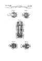
FIG. 3 is a cross-sectional view in a horizontal plane along the lines III-III of FIG. 2;
FIG. 4 is a cross-sectional view in a horizontal plane along lines IV-IV of FIG. 2;
FIG. 5 is a cross-sectional view in a vertical plane of a portion of the apparatus of FIGS. 1 and 2;
FIGS. 6 and 7 are cross-sectional views in a horizontal plane along the lines VI-VL with the lever-actuated shorting switch in opened and closed settings;
FIG. 8 is an electrical schematic circuit diagram of the apparatus during the capacitor charging portion of the cycle of operation in which a voltage is generated by the piezoelectric elements as pressure is applied thereto; and
FIG. 9 is a schematic electrical circuit diagram of apparatus embodying my invention during the brief period that the photoash lamp is connected to the capacitor by way of a closed switch and is red as a result of the charge from the capacitor.
Particular reference is made now to the drawings, in which like reference numerals are used throughout to designate like parts, for a more detailed understanding of the'invention, and in particular to FIG. 1 thereof. A reector 10 having a photoilash bulb or lamp 11 mounted therein is mounted by way of a bracket, not shown in FIG. 1, upon a head portion 13 disposed upon and secured to a flash gun body generally designated 14. The gun body 14 may be generally cylindrical in shape and may be composed of preferably lightweight insulating material having the necessary mechanical strength, for example, a suitable plastic. The plastic case or body 14 has two olf-centered' longitudinally extending cavities designated 15 and 16 located therein, FIG. 2. The cavity 15, as will become more fully apparent hereinafter, has disposed therein two piezoelectric elements which are electrically in parallel and mechanically in series, and which are adapted to be compressed together and released simultaneously 'by lever means hereinafter to be described in detail, the hand operated lever being shown at 17. Disposed in the lower cavity 16 is a capacitor and leads interconnecting the electrodes of the piezoelectric elements, the capacitor and cables which run to the photoflash lamp and to the switch on the camera apparatus, not shown in FIG. 2. The aforementioned head portion 13 is secured to body member 14 by screws 18 and 19, the frontportion of the head 13 having the cut away section at 20 for permitting free movement of the lever 17. At the bottom of the plastic case 14 as seen in FIG. 1 there is a latch member 21, adaped to be hand released, for securing the lever 17 adjacent the body 14 .after the lever has been hand actuated, and retaining the lever in place until the latch 21 is pressed down, releasing the lever. As will appear more fully hereinafter, the compressed piezoelectric elements tend to expand when latch 21 is released, and tend to restore the lever to the position shown in dashed outline in FIG. 2.
As previously stated, FIG. 2 is a cross-sectional view through the apparatus of FIG. l. A bracket 12 is secured to the reflector 10, and is secured to head 13 by the bolt or rivet 23. The Hash bulb 11 is mounted in a socket 24 which has a two conductor insulated cable 25 connecting the socket of the flash bulb to a double socket or socket region generally designated 26 in the body I14, for purposes which will become hereinafter more clearly apparent.
The heart of the electrical generator consists of a pair of piezoelectric elements which are electrically connected in parallel and are mechanically connected in series to be compressed at the same time and to have the pressures thereon released simultaneously. To this end the aforementioned cavity in insulating body 14 is provided. Disposed in cavity 15 are two similar piezoelectric elements 34 and 35, separated from each other by metallic disc or contact member 33, the metallic disc or contact member 37fbeing disposed in cavity 15 at the lower end of element 35, and the metallic disc or contact member 40 being dispose-d in cavity 15 adjacent the upper end of piezoelectric element 34.
The insulating body member 14 lis seen, FIG. 5, to have bores 30 and 31 extending longitudinally thereof on either side of cavity 15 in the wall portion, the bores 30 and 31 having disposed therein electrical conductors or rods 29 and 32 respectively. The conductor 32 is electrically connected near the central portion thereof to the metallic contact member or electrode 33. Member 33 may be displaced slightly when the piezoelectric elements are compressed; accordingly, electrical connection between rod 32 and contact plate 33 is by way of spring biased ball 91, spring 88, and screw 90 in threaded bore 89 in rod 32. Screw 90 is inserted through wall aperture 92 covered by plug 93 which may be cemented in place.
The metallic contact plate or electrode 37 does not move an appreciable amount when the piezoelectric elements -are compressed; accordingly the contact plate 37 is electrically connected to rod 29 by screw 102 in bore 101 in rod 29, screw 102 having been inserted through wall aperture 103 closed by plug 104. Disposed adjacent the upper end -of piezoelectric member 34 is the aforementioned metallic contact plate `or electrode 40; plate 40 is displaced downward when the piezoelectric elements are compressed by action of lever 17, and accordingly electrical connection between contact plate 40 and rod 29 is by way of spring biased ball `97, spring 94, and screw 96 in threaded bore 95 in rod 29, screw 96 being inserted through wall aperture 98 sealed by plug 99 which may be cemented in place after the spring tension is adjusted. The purpose of the rod 29 is to electrically connect the plate or electrode 40 to the contact plate or electrode 37, so that the two piezoelectric elements 34 and 35 are electrically in parallel, the contact 'plate 33 forming one common connection thereto, and the plates or electrodes 37 and 40 connected together forming the other electrical connection thereto.
Disposed on top of electrode 40 is an insulating disc 43 of mica or other suitable insulating material, to electrically insulate electrode 40 from lever 17. Metallic disc 50 is provided to have pressure exerted thereagainst by the protruding hump 27 of lever 17.
As seen in FIG. 5, rods 29 and 32 extend downward in their respective bores 30 and 31 below the level of the lower contact plate 37. They are utilized to provide electrical connections to a storage capacitor located in the lower chamber 16, and in addition rods 29 and 32 are arranged to be short-circuited at a time corresponding to a predetermined position of lever 17 after it is released, to thereby dissipate the charge in the capacitor resulting from electrical energy generated by piezoelectric elements l34 and 35 as they expand when lever 17 is released from latch 21. Depending upon the extent of movement of lever 17, rods 29 and 32 may be momentarily shortcircuited at the moment when, or shortly before, compressing the lever starts to compress the elements, but this momentary short circuit is removed from the capacitor so as not to interfere with the charging thereof.
Two stifIr exposed ends 38 yand 41' of two insulated conductors 38 and 41 extend into two bores 39 and 42 connected with chamber 16, the bores 39 and 42 extending upwardly through the body 14 of insulating material, and being parallel to and spaced equally from bores 30 and 31 respectively. A bore 58 extends through the body 14 in a horizontal direction and transverse to bores 39 and 42, bore 58 having a member 59 of insulating material movably or slidably disposed therein for purposes to become more clearly apparent hereinafter.
Lead or rod 38' is electrically connected to rod 29 by screw 107 in threaded bore 108 in rod 29, screw :107 being inserted through aperture 109 in the wall of body 14, aperture 109 being closed by plug 110 which may be cemented in place. Lead or rod 41 is electrically connected to rod 32 by screw 112 in threaded bore 113 in rod 32, `screw 112 being inserted through aperture 114 in the wall of body 14, aper-ture i114 being closed by plug 115 which may be cemented in place.
.The laforementioned cavity 16 is .seen :in FIG. 2 to have the lower end closed by a cover member 45 retained in position by `set screw 46 in threaded bore 67. In chamber .16 is disposed the capacitor 47, which has two electrical terminals 48 and 49. The aforementioned socket portion 26 is seen to be adapted to receive the terminals of the plug of the aforementioned cable 25 which connects the apparatus to the llash bulb, yand also the two terminal plug of a cable 51 which is conne'cted to the camera and which is terminated in a normally open switch 87 shown in FIGS. 8 and 9, the closing operation of which is synchronized with the operation of the camera shutter by means, not shown. The two terminals of the plug 52 of cable 25 are designated 53 and 54, whereas the two terminals of the plug 55 of cable 51 are designated 56 and 57. Inside the cavity or chamber 16, the terminal 53 has the aforementioned lead or conductor 41 connected thereto, which connects the terminal 53 to the electr-ode or contact plate 33, and the aforementioned terminal '53 is also connected by way of the insulated portion of lead 41 to one terminal 48 of the aforementioned capacitor 47. The other terminal 54 of plug 52 is connected by way of a metallic portion "62 o'f the socket 26 to the upper terminal 56 of plug 55, completing a direct :connection between one lead of the cable 25 going to the photoflash lamp and one lead of the cable 51 connected to t-he camera switch, this portion 62 corresponding to the lead 62 of FIG. 8 hereinafter to be described in more detail. The Iother terminal 49 of capacitor 47 is connected inside the cavity 16 by way of lead 38 to the aforementioned terminal 57 of plug 55, and from lead 38 by way of rod 29 to electrodes 37 and 40.
Particular reference is made now to FIG. 4, in which a cross-sectional view along the line lV-IV of FIG. 2 is shown. It is seen again that the ball 91 is held against the contact member 33 by pressure of spring 88. After the pressure of spring 88 is adjusted to a desired and satisfactory value, aperture 92 is closed by plug 93, which may be cemented in place.
Particular reference is made now to FIG. 3, a crosssectional view looking downward through the line lII-III of FIG. 2. The lever 17 is seen to be pivotally mounted for rotary movement about the longitudinal axis of the pivot pin 68, the ends of which extend into bores 69 and 70 in the body portion 14.
In FIG. 2, the lever 17, pivoted at 68, is seen to have th'e aforementioned downwardly extending hump or pressure portion 27 which is adapted upon clamping the lever 17 to the body 14 to apply pressure tothe top of the piezoelectric element 34 through the pressure plate 50, the insulating disc 43, and the electrode 40. Since both element 34 and electrodes 33 and 40 are freely mounted for longitudinal movement with respect to the axis of cavity 15, the pressure is also applied to piezoelectric elem'ent 35. The lever 17 may be composed of any suitable material.
Particular reference is made again to FIG. l, where it is seen that the lower portion ofthe cover member 45 includes two extended wall portions 75 and 76. Mounted between these two extended wall portions 75 and 76 is a pivot pin 77, FIG. 2, upon which is rotatably mounted the spring biased lock 21. The right-hand end of the spring biased lock lever, as shown in FIG. 2, has a small bore 78 therein to receive a pin 79 for holding in place a biasing spring 80, the upper end of the biasing spring 80 being mounted in a suitable bore 81 in the cover member 45. Disposed on the other side of the pivot pin 77 in a threaded bore 82 is an adjustable set screw 83. In the operation of the locking mechanism, the end 84 of lever 17 forces the left-hand end of the lock lever downward, as seen in FIG. 2, until the catch portion 85 is passed, whereupon the spring 80 forces the catch 21 into locking position.
In understanding the operation of the apparaus, it should be borne in mind that one purpose of the invention is to have a potential or charge readily available in the capacitor 47 to energize the Hash bulb 11 in synchronism with the shutter operation of a camera. It should also be recalled that the shutter-synchronized switch 8-7 shown in FIGS. 8 and 9 is normally open. Assume now by way of description that it is desired to charge the capacitor 47 prior to utilizing or igniting the tia-sh bulb. The lever 17 is grasped and pressed toward the body 14 of the device, causing the pressure portion 27 to press downwardly upon the pressure plate Si) and contact member or electrode 4t). The pressure exerted upon 40 changes the dimensions of the two piezoelectric elements 34 and 35, creating stresses therein, causing the generation of voltages or signals thereacross, as will be readily understood by those skilled in the art. The generation of a potential by `a piezoelectric substance upon the application of mechanical forces thereto is well understood and need not be described in detail. The use of two piezoelectric elements electrically connected in parallel and disposed in series mechanically provides an ecient arrangement for increasing the energy available for charging the capacitor 47. For a further discussion of such an arrangement, reference may be had to an article entitled Piezoelectric Ignition Developed for Small Engines, by Edwin Crankshaw and R. Arnold, appearing in the S.A.E. Journal, vol. 69, August 1961, pages 46-50. The lever, upon reaching the locking position shown in FIG. 2, exerts no additional force thereafter on the piezoelectric members 34- and 35, which remain in their compressed conditions while the lever is latched adjacent the body 14. The signal energy from the two parallel-connected piezoelectric devices 34 and 35 charges the aforementioned capacitor 47, and since no subsequent or immediate relaxation of the pressure on the piezoelectric elements take place, the capacitor does not discharge into the Ielements although the electrical connections thereto remain intact.
At a suitable time the switch 87, FIGS. 8 `and 9 is closed and the charge from capacitor 47 owing through the switch 87 immediately ignites the lamp 11. When the lever is released after the flash gun has been used, the two piezoelectric elements expand to their previous uncompressed conditions, and this expansion generates a voltage which may be stored momentarily at least in part in capacitor 47. Particular reference is made now to FIGS. 6 and 7 where shorting switch means generally designated 44 and operatively connected to the lever 17 is shown for momentarily Shorting the capacitor 47 at a predetermined point in the movement of the lever away from the body, to discharge the capacitor.
FIGS. 6 and 7 are cross-sectional views in a horizontal plane along the line VI-VI of FIG. 2, showing the lever and shorting mechanism or Shorting switch 44 linked thereto in unshorted and shorted positions respectively. In FIG. 6, lever 17 is seen to have pivotally connected thereto one end of the link 22, the link passing into the transverse bore 58 and having the other end thereof passing into a slot 119 in the adjacent end of slidable member 59, link 22 being pivotally connected to member 59 by pivot pin 120. Member 59 has a substantially horizontal bore 122 extending thereacross, in which are disposed metallic balls 123 and 124 normally pressed apart by metallic spring 125. As member 59 slides in bore 58, the balls 123 and 124 ride or slide along the adjacent walls of the insulating body 14.
In FIG. 7, to which particular attention is directed; member 59 is shown moved to the left as a result of release of lever 17, and it is seen that bore 122 is now substantially aligned with rods or leads 38 and 41', so that an electrical short circuit exists at least momentarily between leads 38 and 41' by way of ball 123, spring 125, and ball 124. This discharges capacitor 47, the terminals of which are directly connected to leads 38 and 41.
Particular reference is made now to FIG. 9, which shows the electrical circuit as the photoflash lamp is being ignited, and it will be seen that the capacitor 47 is directly connected across the photoilash lamp by way of the switch 87 in the camera, the operation of which is synchronized with the shutter mechanism. Whereas the electrical connections between the capacitor and electrodes of the piezoelectric `elements remain intact during this portion of the cycle of operation, it will be understood that the piezoelectric elements have a very high resistance, so that no substantial discharge of the capacitor takes place through the elements. In FIG. 9, `Shorting switch 44 is shown as being open. Shorting switch 44 is also open during the pressure-applying portion of the cycle of operation, and accordingly switch 44 is shown open in FIG. 8.
There has been provided then apparatus well suited to accomplish the aforedescribed objects of the invention, which are to provide a ash gun for igniting a photoash lamp, in which the necessity for batteries is dispensed with, and in which piezoelectric generating means are employed while avoiding any mechanical shock to the apparatus at the moment of taking the picture which would result in blurring of the picture.
If desired, the socket portion 26 may be moved to a position further up on the back of the housing 14 so as not to be directly back of the nger grip portion of the lever arm 17.
A number of suitable piezoelectric materials may be employed at 34 and 35, one suitable material being a lead-zirconate-titanate ceramic known in the trade as PZT. Other suitable materials are barium titanate and quartz.
A voltage of several hundred to several thousand volts may be developed between the electrodes depending upon the material employed and the pressure resulting from the lever action. The energy developed may be a fraction of a joule.
Whereas the invention has been shown and described with respect to an exemplary embodiment thereof which gives satisfactory results, it should be understood that changes may be made and equivalents substituted without departing from the spirit and scope of the invention.
I claim as my invention:
1. A flash gun for phototlash apparatus comprising, in combination, a body member, lever means pivotally connected to the body member, said lever means being adapted to be grasped by the fingers of one holding the body member and pressed toward the body member, latch means on the body member for latching the lever means adjacent the body member, at least one piezoelectric element disposed in said body member in predetermined position with respect to the lever means whereby pressure is applied to the piezoelectric element to create stress in said element when the lever means is forced toward the body member, electrical circuit means including capacitor means operatively connected to the piezoelectric means for storing the electrical energy generated by the piezoelectric element as a charge in said capacitor means, and other circuit means connected to said capacitor means and adapted to deliver the charge of the capacitor means to a photoflash lamp for igniting the same.
2. A Flash gun according to claim 1 including in addition means operatively connected to the lever means for discharging the charge in the capacitor means resulting from expansion of the piezoelectric element after the latch means is released.
3. In camera apparatus having a shutter for taking photoash pictures, in combination, an elongated body member, a photoash lamp, socket means including a reflector for said photoash lamp, means mounting the socket means on said body member near one end thereof, a hand-actuated lever pivotally connected to said body member, a piezoelectric element disposed in said body member in predetermined position with respect to said lever whereby the actuation of the lever to move the lever closer to and farther from said body member compresses and releases the piezoelectric element thereby changing the internal stresses of the element, electrode means connected to the piezoelectric element, the compressing of the piezoelectric element generating an electrical signal, capacitor means in said body member, circuit means connecting the capacitor means to the electrode means whereby the signal generated by the piezoelectric element as the piezoelectric element is compressed is stored as a charge in the capacitor means, switching means, and cable means connecting the switching means and the capacitor means in series to the photoflash lamp, said switching means being normally open, the closing of the switching means causing the charge from the capacitor means to flow through said photoash lamp igniting the same, said switching means being adapted to be closed in synchronism with the camera shutter.
4. Camera apparatus according to claim 3 including in addition circuit means operatively connected to the lever and the capacitor means for discharging the charge in the capacitor means resulting from expansion of the piezoelectric element after the lever is released.
5. In flash gun apparatus for energizing a photoflash lamp, in combination, a housing having first and second cavities therein, insulating means including at least one insulating member disposed in said first cavity, said insulating member having a bore therein, a rst electrode disposed in said bore, a first piezoelectric element disposed in said bore with one end thereof adjacent the first electrode, a second electrode disposed in said bore adjacent the other end of said first piezoelectric element, a second piezoelectric element disposed in said bore with one end thereof adjacent said second electrode, a third electrode disposed in said bore adjacent the other end of the second piezoelectric element, a capacitor disposed in said second cavity, electrical circuit means interconnecting said first, second, and third electrodes for connecting said first and second piezoelectric elements in parallel across said capacitor, means adapted to have a force applied thereto for simultaneously applying pressure to the first and second piezoelectric elements to stress both elements for causing the generation of signals therein as the pressure is applied to said first and second piezoelectric elements, said signals being stored as a charge in said capacitor, and circuit means connected to the capacitor and the lamp for utilizing the charge in the capacitor to ignite the lamp.
6. A flash gun for a photoash apparatus comprising:
(a) a ash gun body member;
(b) at least one piezoelectric means disposed in said body member;
(c) manually operable means connected to said body member and contacting said piezoelectric means and operable both to apply a stress to said piezoelectric means and to relieve a stress applied to said piezoelectric means, and said piezoelectric means operable to generate an electric charge both when stress is applied thereto and relieved therefrom;
(d) a photoiiash lampholder and a reflector secured to said body member, said photoflash lampholder adapted to retain a photoflash lamp in operative position with respect to said reflector;
(e) electrical circuit means including capacitor means operatively connected to said piezoelectric means for storing the electrical energy generated by piezoelectric means as a charge in said capacitor means, and additional circuit means connected to said capacitor means and adapted to deliver the charge of said capacitor means to said photoflash lamp for igniting the same; and
(f) means operatively connected to said manually operable means to short out any charge from said capacitor means resulting from relief of stress in said piezoelectric means.
7. A flash gun according to claim 6 in which said other circuit means is additionally characterized as including normally open switching means adapted to be closed in synchronism with a camera shutter.
8. A fiash gun for use with a camera having a shutter comprising, in combination, a photoiiash lamp, reiector means for mounting the photoflash lamp, gun body means, means mounting the reflector means on said body means at one end thereof, lever means pivotally connected to the body means, a piezoelectric element disposed in the body means in predetermined position with respect to the lever means whereby operating lever means in a predetermined manner compresses the piezoelectric element and creates stresses therein, elecrode means for the piezoelectric element for deriving an electric signal from the piezoelectric element when the piezoelectric element is stressed, capacitor means in the body means, circuit means connecting the capacitor means to the electrode means whereby the signal energy generated by the piezoelectric element is stored as a charge in the capacitor means, and other electrical circuit means connecting the capacitor means to the photoash lamp, said other electrical circuit means including normally open switching means adapted to have the closing thereof synchronized with the operation of the camera shutter, said capacitor means delivering its charge to the photoiash lamp upon the closing of the switching means thereby igniting the photoflash lamp, and means operatively connected to the lever means for discharging the charge in the capacitor means resulting from expansion of the piezoelectric element after the lever means is released.
References Cited by the Examiner UNITED STATES PATENTS r2,614,409 l0/52 Malone 95-1l.5 X 2,972,937 2/61 Suits 95--l1.5
JOHN M. HORAN, Primary Examiner.
Claims (1)
1. A FLASH GUN FOR PHOTOFLASH APPARATUS COMPRISING, IN COMBINATION, A BODY MEMBER, LEVER MEANS PIVOTALLY CONNECTED TO THE BODY MEMBER, SAID LEVER MEANS BEING ADAPTED TO BE GRASPED BY THE FINGERS OF ONE HOLDING THE BODY MEMBER AND PRESSED TOWARD THE BODY MEMBER, LATCH MEANS ON THE BODY MEMBER FOR LATCHING THE LEVER MEANS ADJACENT THE BODY MEMBER, AT LEAST ONE PIEZOELECTRIC ELEMENT DISPOSED IN SAID BODY MEMBER IN PREDETERMINED POSITION WITH RESPECT TO THE LEVER MEANS WHEREBY PRESSURE IS APPLIED TO THE PIEZOELECTRIC ELEMENT TO CREATE STRESS IN SAID ELEMENT WHEN THE LEVER MEANS IS FORCED TOWARD THE
Priority Applications (1)
| Application Number | Priority Date | Filing Date | Title |
|---|---|---|---|
| US284704A US3211069A (en) | 1963-05-31 | 1963-05-31 | Flash gun for photoflash lamps and piezoelectric ignition energy generating apparatus for use therein |
Applications Claiming Priority (1)
| Application Number | Priority Date | Filing Date | Title |
|---|---|---|---|
| US284704A US3211069A (en) | 1963-05-31 | 1963-05-31 | Flash gun for photoflash lamps and piezoelectric ignition energy generating apparatus for use therein |
Publications (1)
| Publication Number | Publication Date |
|---|---|
| US3211069A true US3211069A (en) | 1965-10-12 |
Family
ID=23091212
Family Applications (1)
| Application Number | Title | Priority Date | Filing Date |
|---|---|---|---|
| US284704A Expired - Lifetime US3211069A (en) | 1963-05-31 | 1963-05-31 | Flash gun for photoflash lamps and piezoelectric ignition energy generating apparatus for use therein |
Country Status (1)
| Country | Link |
|---|---|
| US (1) | US3211069A (en) |
Cited By (23)
| Publication number | Priority date | Publication date | Assignee | Title |
|---|---|---|---|---|
| US3430080A (en) * | 1965-10-20 | 1969-02-25 | John J Horan | Piezo electric high-voltage alternators and generators |
| US3463943A (en) * | 1968-12-23 | 1969-08-26 | Clevite Corp | Piezoelectric voltage source |
| US3469119A (en) * | 1966-04-11 | 1969-09-23 | Clevite Corp | Rolling cam actuated piezoelectric voltage source |
| US3500451A (en) * | 1967-06-29 | 1970-03-10 | Gen Telephone & Elect | Piezoelectric voltage generator |
| US3558903A (en) * | 1966-06-25 | 1971-01-26 | Rion Co | Mechanically activated piezoelectric voltage source |
| US3558938A (en) * | 1967-09-25 | 1971-01-26 | Robertshaw Controls Co | Piezoelectric voltage source for ignition means |
| US3598030A (en) * | 1969-09-29 | 1971-08-10 | Eastman Kodak Co | Electric generator drive mechanism |
| US3703132A (en) * | 1969-09-29 | 1972-11-21 | Eastman Kodak Co | Electric generator drive mechanism |
| US3726195A (en) * | 1969-11-12 | 1973-04-10 | Agfa Gevaert Ag | Photoflashunit for photographic apparatus |
| US3774511A (en) * | 1969-10-27 | 1973-11-27 | Gen Electric | Contact-less initiation of light emission from photo lamps synchronized with camera operation |
| US3782258A (en) * | 1971-12-03 | 1974-01-01 | Philips Corp | Ignition arrangement for a discharge tube |
| US3808418A (en) * | 1973-04-02 | 1974-04-30 | A Conard | Light flashing apparatus |
| US3958258A (en) * | 1975-04-10 | 1976-05-18 | Eastman Kodak Company | Flash shorting mechanism |
| US3967141A (en) * | 1970-12-01 | 1976-06-29 | Dynamit Nobel Aktiengesellschaft | Piezoelectric energy source |
| US4199245A (en) * | 1977-08-19 | 1980-04-22 | Minolta Camera Kabushiki Kaisha | Power source switch for cameras |
| US4206990A (en) * | 1977-10-05 | 1980-06-10 | Minolta Camera Kabushiki Kaisha | Power supplying system for use in an automatic focusing camera |
| US4523261A (en) * | 1982-08-05 | 1985-06-11 | West Philip G | Light source, manually operated |
| US4719534A (en) * | 1986-05-14 | 1988-01-12 | Ward Gary S | Electric shock safety device |
| US5065067A (en) * | 1988-09-08 | 1991-11-12 | Todd Philip A | Piezoelectric circuit |
| WO1997021974A1 (en) | 1995-12-13 | 1997-06-19 | Ealovega George D | Combined mechanical and electro-mechanical firing mechanism for a firearm |
| US6198205B1 (en) * | 1997-12-31 | 2001-03-06 | Richard P. Oberlin | One-shot high-output piezoid power supply |
| US6291900B1 (en) | 1997-09-15 | 2001-09-18 | General Electric Company | Electrical energy management for manually powered devices |
| US6655035B2 (en) | 2000-10-20 | 2003-12-02 | Continuum Photonics, Inc. | Piezoelectric generator |
Citations (2)
| Publication number | Priority date | Publication date | Assignee | Title |
|---|---|---|---|---|
| US2614409A (en) * | 1951-08-09 | 1952-10-21 | Eastman Kodak Co | Flash lamp firing circuit |
| US2972937A (en) * | 1958-03-14 | 1961-02-28 | Gen Electric | Flash apparatus |
-
1963
- 1963-05-31 US US284704A patent/US3211069A/en not_active Expired - Lifetime
Patent Citations (2)
| Publication number | Priority date | Publication date | Assignee | Title |
|---|---|---|---|---|
| US2614409A (en) * | 1951-08-09 | 1952-10-21 | Eastman Kodak Co | Flash lamp firing circuit |
| US2972937A (en) * | 1958-03-14 | 1961-02-28 | Gen Electric | Flash apparatus |
Cited By (26)
| Publication number | Priority date | Publication date | Assignee | Title |
|---|---|---|---|---|
| US3430080A (en) * | 1965-10-20 | 1969-02-25 | John J Horan | Piezo electric high-voltage alternators and generators |
| US3469119A (en) * | 1966-04-11 | 1969-09-23 | Clevite Corp | Rolling cam actuated piezoelectric voltage source |
| US3558903A (en) * | 1966-06-25 | 1971-01-26 | Rion Co | Mechanically activated piezoelectric voltage source |
| US3500451A (en) * | 1967-06-29 | 1970-03-10 | Gen Telephone & Elect | Piezoelectric voltage generator |
| US3558938A (en) * | 1967-09-25 | 1971-01-26 | Robertshaw Controls Co | Piezoelectric voltage source for ignition means |
| US3463943A (en) * | 1968-12-23 | 1969-08-26 | Clevite Corp | Piezoelectric voltage source |
| US3598030A (en) * | 1969-09-29 | 1971-08-10 | Eastman Kodak Co | Electric generator drive mechanism |
| US3703132A (en) * | 1969-09-29 | 1972-11-21 | Eastman Kodak Co | Electric generator drive mechanism |
| US3774511A (en) * | 1969-10-27 | 1973-11-27 | Gen Electric | Contact-less initiation of light emission from photo lamps synchronized with camera operation |
| US3726195A (en) * | 1969-11-12 | 1973-04-10 | Agfa Gevaert Ag | Photoflashunit for photographic apparatus |
| US3967141A (en) * | 1970-12-01 | 1976-06-29 | Dynamit Nobel Aktiengesellschaft | Piezoelectric energy source |
| US3782258A (en) * | 1971-12-03 | 1974-01-01 | Philips Corp | Ignition arrangement for a discharge tube |
| US3808418A (en) * | 1973-04-02 | 1974-04-30 | A Conard | Light flashing apparatus |
| US3958258A (en) * | 1975-04-10 | 1976-05-18 | Eastman Kodak Company | Flash shorting mechanism |
| US4199245A (en) * | 1977-08-19 | 1980-04-22 | Minolta Camera Kabushiki Kaisha | Power source switch for cameras |
| US4206990A (en) * | 1977-10-05 | 1980-06-10 | Minolta Camera Kabushiki Kaisha | Power supplying system for use in an automatic focusing camera |
| US4523261A (en) * | 1982-08-05 | 1985-06-11 | West Philip G | Light source, manually operated |
| US4719534A (en) * | 1986-05-14 | 1988-01-12 | Ward Gary S | Electric shock safety device |
| US5065067A (en) * | 1988-09-08 | 1991-11-12 | Todd Philip A | Piezoelectric circuit |
| WO1997021974A1 (en) | 1995-12-13 | 1997-06-19 | Ealovega George D | Combined mechanical and electro-mechanical firing mechanism for a firearm |
| US5713150A (en) * | 1995-12-13 | 1998-02-03 | Defense Technologies, Llc | Combined mechanical and Electro-mechanical firing mechanism for a firearm |
| US6291900B1 (en) | 1997-09-15 | 2001-09-18 | General Electric Company | Electrical energy management for manually powered devices |
| US6198205B1 (en) * | 1997-12-31 | 2001-03-06 | Richard P. Oberlin | One-shot high-output piezoid power supply |
| US6655035B2 (en) | 2000-10-20 | 2003-12-02 | Continuum Photonics, Inc. | Piezoelectric generator |
| US20040108724A1 (en) * | 2000-10-20 | 2004-06-10 | Continuum Control Corporation, A Massachusetts Corporation | Piezoelectric generator |
| US6909224B2 (en) | 2000-10-20 | 2005-06-21 | Continuum Photonics, Inc. | Piezoelectric generator |
Similar Documents
| Publication | Publication Date | Title |
|---|---|---|
| US3211069A (en) | Flash gun for photoflash lamps and piezoelectric ignition energy generating apparatus for use therein | |
| US3782258A (en) | Ignition arrangement for a discharge tube | |
| US2972937A (en) | Flash apparatus | |
| US4523261A (en) | Light source, manually operated | |
| SE8001048L (en) | ELECTRIC RELEASING DEVICE FOR FIREARMS | |
| US3127112A (en) | Photographic flash tube and reflector | |
| DE1246390B (en) | Camera with attachable flash unit | |
| US2447832A (en) | Photographic flash apparatus | |
| US4242616A (en) | Photographic flash apparatus | |
| CA1090409A (en) | Piezo-electrically actuated electronic flash l.c. ignition circuit | |
| US3521540A (en) | Electronic flash unit for cameras adapted to receive flashcubes | |
| US3846806A (en) | Automatic flash device for a photographic camera | |
| US4095245A (en) | Adapter for electronic flash apparatus | |
| US2740339A (en) | Photo-flash unit | |
| US3781602A (en) | Electronic flash circuits | |
| US2480122A (en) | Electron discharge apparatus | |
| US3344314A (en) | Igniter employing a piezoelectric voltage source | |
| US3742298A (en) | Arc gap circuits for flashing high voltage photoflash lamps | |
| US571909A (en) | Charles e | |
| US3880572A (en) | Piezoelectric flash lamp ignition | |
| US4059387A (en) | Flash lamp unit | |
| US2295071A (en) | Photoflash unit | |
| US3106080A (en) | Flash apparatus | |
| US1869158A (en) | Photographer's flash light apparatus | |
| US4245279A (en) | Photoflash unit with inverted flashlamps |