US3209204A - Phase to ground protective systems - Google Patents
Phase to ground protective systems Download PDFInfo
- Publication number
- US3209204A US3209204A US170991A US17099162A US3209204A US 3209204 A US3209204 A US 3209204A US 170991 A US170991 A US 170991A US 17099162 A US17099162 A US 17099162A US 3209204 A US3209204 A US 3209204A
- Authority
- US
- United States
- Prior art keywords
- voltage
- line
- phase
- relaying
- terminals
- Prior art date
- Legal status (The legal status is an assumption and is not a legal conclusion. Google has not performed a legal analysis and makes no representation as to the accuracy of the status listed.)
- Expired - Lifetime
Links
Images
Classifications
-
- H—ELECTRICITY
- H02—GENERATION; CONVERSION OR DISTRIBUTION OF ELECTRIC POWER
- H02H—EMERGENCY PROTECTIVE CIRCUIT ARRANGEMENTS
- H02H3/00—Emergency protective circuit arrangements for automatic disconnection directly responsive to an undesired change from normal electric working condition with or without subsequent reconnection ; integrated protection
- H02H3/40—Emergency protective circuit arrangements for automatic disconnection directly responsive to an undesired change from normal electric working condition with or without subsequent reconnection ; integrated protection responsive to ratio of voltage and current
- H02H3/402—Emergency protective circuit arrangements for automatic disconnection directly responsive to an undesired change from normal electric working condition with or without subsequent reconnection ; integrated protection responsive to ratio of voltage and current using homopolar quantities
Definitions
- Alternating electric systems may be resistance-grounded or solidly-grounded.
- solidly-grounded systems are in the majority in this country.
- the invention is particularly suitable for the solidly-grounded systems.
- a distance relaying assembly is located at a relaying station on a polyphase electric system to be protected.
- Polyphase voltages derived at the relaying station are compensated by series compensators for the purpose of producing a set of compensated polyphase relaying voltages which represent the voltages present at a predetermined point on the electric system which is substantially displaced from the relaying station. This point will be referred to as the balance point or reach of the relaying assembly.
- a voltage is derived which represents the zero-sequence voltage at the balance point if the fault is at that point or beyond. If a line-to-ground fault occurs on the electric system at the balance point it will be found that the derived zero sequence voltage is equal in magnitude and opposite in phase to the line-to-neutral voltage at the balance point of the grounded line. Line-to-neutral voltage is defined as the sum of the positive-and-negative sequence voltages.
- the relaying assembly is responsive to the difference between this derived zero-sequence voltage and the derived line-to-neutral voltage of the grounded line.
- the derived zero-sequence voltage becomes larger than the line-to-neutral voltage of the grounded line and the relaying assembly trips an associated breaker.
- the response of the relaying assembly is inherently directional. This means that the relaying assembly does not respond to a ground fault if the relaying station is located between such a ground fault and the balance point. Such a fault may be said to be behind the relaying assembly. In some cases the relaying assembly may respond to a ground fault which is slightly behind the relaying station. Under certain conditions this may provide back-up protection for such close-in faults.
- the relaying assembly may overreach slightly in response to two-line-to-ground faults.
- the relaying assemblies When the relaying assemblies are employed for protecting the conventional zones 1, 2 and 3 of an electric system the slight tendency to over reach for tWo-line-to-ground faults when a moderate amount of fault resistance is present between the phases would not be objectionable for the zones 2 and 3 applications.
- the overreach may not be desirable for a Zone 1 application where accuracy of reach is of greater importance.
- the invention further contemplates that a two-lineto-ground fault in the vicinity of the balance point will block or restrain operation of the relaying assembly.
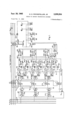
- FIGURE 1 is a schematic view of a polyphase electric system protected by a relaying assembly embodying the invention
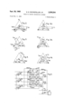
- FIGS. 2, 2A, 3, 3A, 4 and 4A are vector diagrams showing vector relationships which may occur in the system of FIGURE 1;
- FIG. 5 is a schematic view showing modified circuits which may be employed for responding to the presence of a two-line-to-ground fault on the system of FIG- URE 1.
- FIG. 1 shows a three-phase line section 11 which is to be protected.
- This line section has lines or phase conductors A, B and C.
- the line section is connected at a relaying station to a three phase bus 12 through a circuit breaker CB.
- a set of line-current transformers CT derive the currents I I and I and the star-point current 31 for relaying purposes wherein I is the zero sequence component of the line currents.
- a set of potential transformers PT is employed for deriving the lineor bus-voltagesto-neutral respectively V V and V for relaying purposes. It will be noted that the potential transformers have three primary windings PTA, PTB and PTC connected in star with a grounded neutral.
- Each of the primary windings has two secondary windings associated therewith.
- One set of the secondary windings is connected in star with a grounded neutral to provide the secondary line-to-neutral voltages V V and V (T o simplify the presentation a one-to-one transformer ratio is assumed.)
- the remaining set of secondary windings is connected in a closed series circuit with a resistor R which serves as a voltage divider.
- the output of the voltage divider is a voltage V which represents the zero-sequence-component of the line voltages.
- FIG. 1 conventional polarity markings are applied to the various transformer windings.
- FIG. 2A shows the corresponding voltages at bus 12, some distance from the fault point.
- V V and V are derived which correspond to the three line-toneutral voltages of the associated bus.
- the transformers may have any desired transformation ratio, for present purposes it will be assumed that the transformers have a one-to-one transformer ratio.
- the voltages V V and V across the secondary windings of the potential transformer PT are applied through three compensators CP respectively across the primary windings APTA, APTB and APTC of an auxiliary potential transformer APT. These primary windings are connected in star but with the neutral point ungrounded.
- the compensator CP associated with the voltage V has it primary winding T energized in accordance with the current I If the impedance introduced by the compensator CP is made equal to the positive-sequence impedance from the relaying station to the point of fault F the difference between the voltage V and the drop across the compensator is a voltage V which is applied across the primary winding APTA of the auxiliary potential transformers associated therewith.
- the voltage V corresponds to the voltage V of FIG. 2.
- Each of the compensators CP preferably is provided with a tapped primary winding T having a small number of turns and a secondary winding having a larger number of turns, the two windings being interlinked to an airgapped core 16 so that the compensator voltage which is generated in the secondary winding 15 will be substantially 90 or less out of phase with the current which flows through the primary winding T.
- the compensator may be similar in construction to that shown in Patent 2,973,- 459 of W. K. Sonnemann and in patent application Serial No. 91,394 filed February 24, 1961, by William K. Sonnemann. As shown in the aforesaid patent, resistance may be connected across a portion of the secondary winding of the compensator to control the phase relationship between the compensator voltage and the primary current.
- the air-gap compensator provides an effective transient shunt which tends to remove any direct-current transient from the energy supplied to the relays. It should be noted that no conductive connection exists between the circuits of the current and potential transformers.
- the voltage V is associated with a compensator CP which has its primary Winding energized by the current I to provide a voltage V which corresponds to the voltage V of FIG. 2.
- the voltage V is associated with a compensator having its primary Winding energized by a current corresponding to the current 1 to produce a voltage V which corresponds to the voltage V of FIG. 2.
- Each primary winding of the auxiliary potential transformers has two secondary windings associated therewith.
- the primary winding associated with the voltage V has two secondary windings 17 and 18. It will be assumed that the transformer ratio in each case is a one-to-one ratio, and the reference character V will be employed for the-voltage across each of the windings.
- the voltage V across the secondary winding 18 is applied to the input terminals of a full wave rectifier PR4.
- the output terminals of the rectifier are connected across a load resistor R8 which has a filter capacitor C4 shunted thereacross.
- a direct voltage appears across the resistor R8 which corresponds to the voltage V
- a direct voltage is applied across a resistor R9 which corresponds to the voltage V
- a direct voltage is applied across a resistor R10 which corresponds to the voltage V
- the voltage V is associated with a compensator CP which is similar in construction to the compensators CP previously discussed but which provides an impedance equal to one-third of the zero-sequence impedance of the line section from the relaying station to the point of fault F
- the primary winding of the com pensator CP is energized by the residual current compon-ent 31
- the sum of voltage V and the voltage generated by the compensator CP corresponds to the voltage V of FIG. 2 and is applied across the input terminals of a full wave rectifier PR7.
- the direct voltage output V of the rectifier is applied across a filter capacitor C7.
- the voltage V across the capacitor C7 is compared with the smallest of the voltages across or derived from the resistors R8, R9 and R10.
- a terminal 23 is connected to a tap on each of the resistors R8, R9 and R10 through a separate rectifier BRIS, BR14 or BR15.
- the taps provide voltages V V and V respectively.
- a terminal 21 is connected to the negative end of each of the resistors R8, R9 and R10 and to the negative output terminal of the rectifier PR7.
- the positive output terminal of the rectifier PR7 is connected to the terminal 23 through a resistor R7, and a resistor R12.
- the voltage V across the output part of the resistor R8 is less than the output voltage of the rectifier PR7 and that the latter is smaller than the voltages V and V across the output parts of the resistors R9 and R10.
- the rectifiers BR14 and BRIE block the flow of current from the resistors R9 and R10 through the rectifier BR13 and the resistor R8 to the common terminal of the resistors.
- current can flow from the positive terminal of the rectifier PR7 through the resistors R7 and R12, the rectifier BR13, the lower part of the resistor R8 and the terminal 21 to the negative terminal of the rectifier PR7.
- a system may be so designed that the voltage across the resistor R12 is employed directly for tripping the circuit breaker CB.
- the circuit breaker CB is provided with a trip coil TC and an auxiliary switch Ba.
- the auxiliary switch is closed when the circuit breaker is closed and is open when the circuit breaker is open.
- the trip coil is connected through the auxiliary switch across the make contacts of a relay GF-l.
- the operating coil of the relay GP-l is energized in accordance with the voltage across the resistor R12 through a suitable amplifier 25.
- zones 1, 2 and 3 In the application of distance-relaying protection to line sections it is common practice to divide the line section to be protected into three overlapping Zones which are referred to as zones 1, 2 and 3. It will be assumed that the relay GP-I and its energizing circuits are designed to provide zone 1 protection for the line section 11 against single-line-to-ground faults. The operation of the portion of FIGURE 1 which has been described in detail above now will be reviewed.
- Each of the compensators CP has an impedance Z which is defined as the ratio of secondary induced voltage to primary current.
- Z is defined as the ratio of secondary induced voltage to primary current.
- the impedance of the compensator is selected in accordance with the zone for which it is designed or on the distance of the balance point from the relaying station. It will be assumed that the compensator impedance is equal to the positive-sequence impedance of the line section from the relaying station to the desired balance point.
- the impedance of the compensator CP is made equal to one-third the impedance Z multiplied by the ratio of the zero-sequence impedance to the positive-sequence impedance from the relaying station to the desired balance point.
- the impedance Z is assumed to be equal to the positive-sequence impedance it follows that for the assumed conditions the impedance of the compensator CP is equal to one-third the zero-sequence im pedance from the relaying station to the balance point.
- the relaying assembly thus far described in detail inherently is essentially directional.
- the relaying assembly will respond to a single-line-to-ground fault occurring between the relaying station and the balance point.
- the relaying assembly will not respond to a single-line-toground fault occurring behind the relaying station or to the left as viewed in FIG. 1 except under certain extreme conditions which do not occur in most applications. In a few applications a fault immediately behind the relaying station involving one line and ground may trip the circuit breaker CB. Such applications occasionally may be encountered if the relaying assembly is set for third zone operation but are not likely to be encountered for relaying assemblies set for second zone operation and would not be encountered for relays set for first zone operation.
- the relaying assembly When the relaying assembly is employed for third zone operation it would be provided with a substantial time delay in operation.
- the extension of the zone to include a small portion of the lines immediately behind the relaying station would provide a desirable backup protection for adjacent single-line-to-ground faults in such areas.
- FIGS. 3, 3A, 4 and 4A Voltage conditions existing in the presence of two-lineto-ground faults are shown in FIGS. 3, 3A, 4 and 4A.
- FIG. 3 shows vector relationships for voltages at the balance point when faults to ground occur on both of the lines A and B. It will be noted that the zero sequence voltage V is equal in magnitude and opposite in direction to each of the line-to-neutral voltages V and V The zero-sequence voltage V is in phase with the voltage V but has only half the magnitude of the latter voltage.
- FIGURE 3A shows the corresponding voltages at the relaying station.
- FIG. 4 vector relationships are shown for the voltages at the balance point when the lines A and C are grounded at the balance point. It will be noted that the zero-sequence voltage V in FIG. 4 is equal in magnitude but opposite in phase relative to the voltages V and V FIG. 4A shows the corresponding voltage relationships at the relaying station.
- FIG. 1 The portion of FIG. 1 which thus far has been described in detail responds to two-line-to-ground faults occurring within the reach of the relaying assembly.
- the relaying assembly may over-reach slightly on two-line-to-ground faults when a moderate amount of fault resistance is present between the faulted lines. This slight over-reach would not be objectionable in relaying assemblies for zone 2 or zone 3 operation.
- accuracy of reach is of greater importance in zone 1 applications the small over-reach on two-line-to-ground faults probably would be acceptable in a number of zone 1 applications.
- the input circuit for the amplifier 25 includes a resistor R7.
- a direct voltage is developed across the resistor R7 having a polarity represented by conventional polarity marks for positive and for negative. It will be noted that this voltage is in a direction opposing the voltage V
- the voltage across the resistor R7 may be made large enough to completely block operation of the amplifier 25 or it may be made merely large enough to prevent operation of the amplifier 25 in response to two-line-to-ground faults occurring beyond the rated reach of the relaying assembly.
- a constant bias voltage is developed by connecting a constant voltage device such as a Zener diode DZI across the resistor R7. When the voltage of the resistor R7 tends to exceed the breakdown voltage of the Zener diode DZl the diode breaks down to maintain a constant voltage thereacross.
- a detector for detecting the presence of a two-line-to-ground fault.
- one phase quantity differs from the corresponding quantities of the other two phases.
- the currents in the two faulted lines are larger than the current in the nonfaulted lines.
- the voltages-to-neutral of the two faulted lines are smaller than the voltage-to-neutral of the unfaulted line.
- the detector can sense that one of the line currents is substantially smaller than each of the remaining line currents or that one of the line-to-neutral voltages is substantially larger than each of the remaining line-to' -neutral voltages the two-line-to-ground fault conditions can be detected.
- the line-toneutral voltages V V and V are compared. If any of these voltages is substantially larger than each of the remaining voltages, current is supplied to the resistors R7 to develop a restraining or blocking voltage.
- each primary winding of the auxiliary potential transformers APT is provided with two secondary windings.
- the three secondary windings 17 supply voltages V V and V respectively to three full-wave rectifiers, PR1, PR2 and PR3.
- the outputs of the rectifiers are applied respectively across the resistors R1, R2 and R3 each of which is provided with a filter capacitor C1, C2 and C3 respectively.
- Each of the resistors is provided with an adjustable tap which is connected through a rectifier respectively BR4, BRS and BR6 to the positive terminal of the resistor R7.
- the output of the full-wave rectifier PR1 develops a direct voltage V between the tap on the resistor R1 and the negative terminal of the rectifier which is dependent on the alternating voltage V
- the output of the rectifier PR1 also is applied through a rectifier BR7 across a resistor R4 and through a rectifier BRIZ across a resistor R6 to produce across each of the resistors at least a direct voltage V which is dependent on the voltage V
- the rectifier PR2 develops between the tap on the resistor R2 and the negative terminal of the rectifier a direct voltage V which is dependent on the voltage V N.
- the output of the rectifier RPZ is applied through a rectifier BRS across a resistor R5 and through a rectifier BRIO across the resistor R4 to develop across each of these resistors at least a voltage V which is dependent on the voltage V
- the rectifier PR3 develops between the tap on the resistor R3 and the negative terminal of the rectifier a direct voltage V which is dependent on the voltage V
- the rectifier PR3 is connected through a rectifier BR9 across the resistor R6 and through the rectifier BR11 across the resistor R5 to develop across each of these resistors at least a direct voltage V which is dependent on the voltage V
- the negative terminal of the resistor R7 is connected to the left hand terminals of the resistors R4, R5 and R6 respectively through the rectifiers BRl, BR2 and BR3.
- the relay GF-l is controlled to provide zone 1 protection for the line section 11. If zone 2 protection is desired for single-line-to-ground faults a relay GF-Z may be provided which has a control similar to that of relay GF-l except that it is provided with a longer reach suitable for zone 2 protection. The only other difference is that the relay GP-2 is provided with a substantial time delay which is conventional for zone 2 protection. The time delay may be provided in a manner similar to that shown in the aforesaid Sonnemann patent.
- a relay GF-3 may be provided which has a control similar to that provided for the relay GF-ll except that the relay control is provided with a reach suitable for zone 3 protection.
- the relay GP-3 is designed to operate with a time delay which is greater than that that provided for the relay GP2.
- the trip coil TC also may be connected for operation in response to phase-to-phase faults and three phase faults.
- a relay -1 is provided which is responsive to phase-to-phase faults.
- This relay may be similar to the relay bearing the same reference character shown in the aforesaid Sonnemann patent.
- the relay is assumed to provide zone 1 protection.
- Three-phase fault protection is provided by a relay 31 which may be similar to the relay having the same reference character in the aforesaid Sonnemann patent.
- This relay again is assumed to provide zone 1 protection against threephase faults. If zone 2 and zone 3 protection against phase-to-phase and three-phase faults are desired similar phase-to-phase and three-phase fault relays may be provided for zone 2 and zone 3 protection in the manner discussed in the aforesaid Sonnemann patent.
- the additional relays assure full protection in certain extreme cases which are unlikely to be encountered. For example consider the rare system wherein the zerosequence-component of current is substantially zero for a close-in-line-to-ground fault condition. Even though the relay GF-l should fail to respond to this condition it can be shown that such a condition would cause the relay 5 5-1 to operate to protect the system.
- FIG. 1 Provision is made in FIG. 1 for restraining or blocking operation of the relay GF-l in the presence of two-lineto-ground faults adjacent the balance point. As previous.- ly pointed out such restraint or blocking generally is not required for zone 2 and zone 3 operations. For this reason such restraint may be omitted for the relays GF-2 and GF3.
- the taps on the resistors R1, R2 :and R3 may be adjusted to provide any desired ratio of voltages necessary to produce a restraining or blocking operation. As representative of suitable parameters the taps may be adjusted to provide the restraining or blocking operation whenever one of the voltages V V or V is greater than 1.4 times each of the remaining voltages. For a close-in single-line-to-ground fault one of voltages V V or V may be somewhat larger than the remainder of the voltages because of the compensator action.
- the Zener diode DZ1 is selected to limit the restraining voltage thereacross to a small value compared to that of the voltage V
- the maximum voltage across the Zener diode DZ1 may be of the order of fifteen volts as against a voltage of the order of 97 volts for the voltage V for a single-line-to-ground fault. Under such circumstances the voltage V exceeds the minimum of the voltages V V and V by an amount sufficient to ensure operation of the circuit breaker for close-in single-line-to-ground faults despite the presence of the voltage across the Zener diode.
- FIG- URE 1 lends itself admirably to zone packaging.
- all equipment associated with the relay GF-1 may be packaged in a single casing to provide zone 1 protection.
- a separate casing may be employed for the equipment associated with each of the relays GF-2 and GF-3 to provide respectively zone 2 and Zone 3 protection.
- FIG. 1 the outputs of the rectifiers FR1, FR2 and of the resistor R1 through a rectifier BRZl for energization in accordance with the voltage V A resistor R16 is connected through a rectifier BR22 across the lower portion of the resistor R2 for energization in accordance with the voltage V A resistor R17 is connected through the rectifier BR23 for energization across a lower portion of the resistor R3 to produce a voltage V across the resistor R17.
- the upper terminals of the resistors R19, R20 and R21 are connected respectively through rectifiers BR24, BR25 and BR26 to the negative terminal of the resistor R7.
- the positive terminal of the resistor R7 is connected through the rectifiers BR27, BR28 and BR29, respectively, to the lower terminals of the resistors R19, R20 and R21. Consequently, a biasing voltage appears across the resistor R7 which depends on the largest voltage appearing across the resistors R19, R20 and R21.
- a relaying assembly for protecting a polyphase transmission line, a first set of input terminals suitable for energization by polyphase voltages, a second set of terminals suitable for energization by polyphase currents, means for deriving from said first set of input terminals a first quantity dependent on the zero-sequence component of polyphase voltages applied to said terminals, impedance means energized by a zero-sequence current derived from the second set of terminals when the lastnamed terminals are energized by polyphase currents for subtracting from said first quantity a second quantity dependent on a predetermined zero-sequence impedance drop to produce a compensated third quantity, impedance means including a plurality of impedances energized from the second set of terminals for producing a set of phase impedance voltage drops each corresponding to the flow of a separate one of a plurality of phase currents applied to the second set of terminals through one of said impedances, means for subtracting each of said phase im
- a relaying assembly for protecting a polyphase transmission line, a first set of input terminals suitable for energization by polyphase voltages, a second set of terminals suitable for energization by polyphase currents, means for deriving from said first set of input terminals a first quantity dependent on the zero-sequence component of polyphase voltages applied to said terminals, impedance means energized by a zero-sequence current derived from the second set of terminals when the last-named terminals are energized by polyphase currents for subtracting from said first quantity a second quantity dependent on a predetermined zero-sequence impedance drop to produce a compensated third quantity, impedance means including a plurality of impedance energized from the second set of terminals for producing a set of phase impedance voltage drops each corresponding to the flow of a separate one of a plurality of phase currents applied to the second set of terminals through one of said impedances, means for subtracting each of said phase im
- a relaying assembly for protecting a polyphase transmission line, a first set of input terminals suitable for energization by polyphase voltages, a second set of terminals suitable for energization by polyphase currents, means for deriving from said first set of input terminals a first alternating quantity dependent on the zero-sequence component of polyphase voltages applied to said terminals, impedance means energized by a zero-sequence current derived from the second set of terminals when the lastnamed terminals are energized by polyphase currents for subtracting from said first alternating quantity a second alternating quantity dependent on a predetermined zerosequence impedance drop to produce a compensated third alternating quantity, rectifying means for converting said third alternating quantity into a first direct quantity, impedance means including a plurality of impedances energized from the second set of terminals for producing a set of phase impedance alternating voltage drops each corresponding to the flow of a separate one of a plurality of phase current
- a relaying assembly for protecting a polyphase transmission line, a first set of input terminals suitable for energization by polyphase voltages, a second set of terminals suitable for energization by polyphase currents,
- impedance means energized by a zero-sequence cur-rent derived from the second set of terminals when the last-named terminals are energized by polyphase currents for subtracting from said first quantity a second quantity dependent on a predetermined zero-sequence impedance drop to produce a compensated third quantity
- impedance means including a plurality of impedances energized from the second set of terminals for producing a set of phase impedance voltage drops each corresponding to the flow of a separate one of a plurality of phase currents applied to the second set of terminals through one of said impedances, means for subtracting each of said phase impedance voltage drops from a corresponding phase voltage derived from the first set of terminals to produce a set of compensated fourth quantities, and output means for producing an output when said third quantity bears a predetermined relation to said fourth
- impedance means energized by a zero-sequence current derived from the second set of terminals when the last-named terminals are energized by polyphase currents for subtracting from said first quantity a second quantity dependent on a predetermined zero-sequence impedance drop to produce a compensated third quantity
- impedance means including a plurality of impedances energized from the second set of terminals for producing a set of phase impedance voltage drops each corresponding to the flow of a separate one of a plurality of phase currents applied to the second set of terminals through one of said impedances, means for subtracting each of said phase impedance voltage drops from a corresponding phase voltage voltage
- a protective relaying combination for responding to certain faults on a three-phase transmission line, including: means energized from the line voltage at a relaying station for producing a derived three phase voltage for relaying purposes; a line drop compensating means connected in series circuit relation to the first-named means for energization by said derived three phase voltage for reproducing some aspect of the three-phase line voltage at some predetermined fault location in the transmission line to produce a three-phase compensated relaying voltage, means for deriving a quantity dependent on the zero-sequence component of said three-phase compensated relaying voltage, and translating means responsive to the difference between said quantity and the smallest phase voltage of said three-phase compensated relaying voltage.
- a protective relaying combination for responding to certain faults on a three-phase transmission line including: means energized from the line voltage at a relaying station for producing a derived three-phase voltage for relaying purposes; a line-drop compensating means connected in series circuit relation to the first-named means for energization by said derived three-phase voltage for reproducing some aspect of the three-phase line voltage at some predetermined fault location in the transmission line to produce a three-phase compensated relaying voltage, means for deriving a direct first quantity dependent on the zero-sequence component of said threephase compensated relaying voltage, rectifying means for deriving from said three-phase compensated relaying voltage a set of direct second quantities each dependent on a separate phase voltage of said three phase compensated relaying voltage, and translating means responsive to the difference between said direct first quantity and the smallest of the second quantities.
- a protective-relaying combination for responding to certain faults on a three-phase transmission line including: means energized from the line voltage at a relaying station for producing a derived three-phase voltage for relaying purposes; a set of three line drop compensators connected in series circuit relation to the respective phases of said derived three phase voltages, and energized proportionately to the respective line currents in the corresponding line Wires of the transmission line, each of the compensators having an impedance equal to the line imped ance to a predetermined fault location to produce a threephase compensated relaying voltage, zero-sequence dependent means energized from the three-phase line voltage at the relaying station for producing an alternating quantity dependent on the zero-sequence compononet of the threephase line voltage, line drop compensating means connected in series circuit relation to said zero-sequence dependent means for energization by said alternating quantity, and energized proportionately to the zero-sequence component of the line currents of the transmission line, the last-named
- a protective-relaying combination for responding to certain faults on a three-phase transmission line including: means energized from the line voltage at a relaying station for producing a derived three-phase voltage for relaying purposes; a set of three line drop compensators connected in series circuit relation to the respective phases of said derived three phase voltages, and energized proportionately to the respective line currents in the corresponding line wires of the transmission line, each of the compensators having an impedance equal to the line impedance to a predetermined fault location to produce a three-phase compensated relaying voltage, means energized from the three-phase line voltage at the relaying station for producing an alternating quantity dependent on the zero-sequence component of the three-phase line voltage, line drop compensating means connected in series circuit relation to said alternating quantity, and energized proportionately to the zero-sequence component of the line currents of the transmission line, the last-named compensator having an impedance equal to the corresponding line impedance to the predetermined fault location to produce a
- a protective-relaying combination for responding to certain faults on a three-phase transmission line having a relaying station including: means located at said relaying station for producing quantities dependent on the zero-sequence voltage present at a predetermined point on the transmission line substantially displaced from the relaying station, means located at said relaying station for producing quantities dependent on the phase voltages of said transmission line at such predetermined point, and translating means located at the relaying station and energized by said quantities for response to the difference between the zero-sequence voltage and the smallest of said phase voltages.
- a protective-relaying combination for responding to certain faults on a three-phase transmission line having a relaying station including: means located at said relaying station for producing quantities dependent on the zero-sequence voltage present at a predetermined point on the transmission line substantially displaced from the relaying station, means located at said relaying station for producing quantities dependent on the phase voltages of said transmission line at such predetermined point, and translating means located at the relaying station and energized by said quantities for response to the difference between the zero-sequence voltage and the smallest of said phase voltages, and means responsive to conditions present when a two-line-to-ground fault occurs on the transmission line for modifying the response of said translating means to the energization by said quantities.
- a protective-relaying combination for responding to certain faults on a three-phase transmission line having a relaying station including: means located at said relaying station for producing quantities dependent on the zero-sequence voltage present at a predetermined point on the transmission line substantially displaced from the relaying station, means located at said relaying station for producing quantities dependent on the phase voltages of said transmission line at such predetermined point, and translating means located at the relaying station and energized by said quantities for response to the difference between the zero-sequence voltage and the smallest of said phase voltages, said transmission line upon occurrence of a two-line-to-ground fault thereon having voltage and current values for the unfaulted line which differ from the voltage and current values for the faulted lines, and means responsive to the difference between one of said values for 'one of the lines and the corresponding values for both of the remaining lines for restraining said response of the translating means.
- a relaying assembly for protecting a polyphase transmission line, a first set of input terminals suitable for energization by polyphase voltages, a second set of terminals suitable for energization by polyphase currents, means for deriving from said first set of input terminals a first alternating quantity dependent on the zero-sequence component of polyphase voltages applied to said terminals, impedance means energized by a zero-sequence current derived from the second set of terminals when the last-named terminals are energized by polyphase currents for subtracting from said first alternating quantity a sec 'ond alternating quantity dependent on a predetermined zero-sequence impedance drop to produce a compensated third alternating quantity, rectifying means for converting said third alternating quantity into a first direct quanuty, impedance means including a plurality of impedances energized from the second set of terminals for producing a set of phase impedance alternating voltage drops each corresponding to the flow of a separate
Landscapes
- Emergency Protection Circuit Devices (AREA)
Priority Applications (2)
| Application Number | Priority Date | Filing Date | Title |
|---|---|---|---|
| US170991A US3209204A (en) | 1962-02-05 | 1962-02-05 | Phase to ground protective systems |
| JP463963A JPS4020295B1 (mo) | 1962-02-05 | 1963-02-05 |
Applications Claiming Priority (1)
| Application Number | Priority Date | Filing Date | Title |
|---|---|---|---|
| US170991A US3209204A (en) | 1962-02-05 | 1962-02-05 | Phase to ground protective systems |
Publications (1)
| Publication Number | Publication Date |
|---|---|
| US3209204A true US3209204A (en) | 1965-09-28 |
Family
ID=22622090
Family Applications (1)
| Application Number | Title | Priority Date | Filing Date |
|---|---|---|---|
| US170991A Expired - Lifetime US3209204A (en) | 1962-02-05 | 1962-02-05 | Phase to ground protective systems |
Country Status (2)
| Country | Link |
|---|---|
| US (1) | US3209204A (mo) |
| JP (1) | JPS4020295B1 (mo) |
Cited By (8)
| Publication number | Priority date | Publication date | Assignee | Title |
|---|---|---|---|---|
| US3378728A (en) * | 1964-04-28 | 1968-04-16 | English Electric Co Ltd | Electrical protective relay employing phase angle comparators |
| US3401307A (en) * | 1965-03-22 | 1968-09-10 | English Electric Co Ltd | Electrical protective relay arrangement |
| US3405320A (en) * | 1966-05-10 | 1968-10-08 | Westinghouse Electric Corp | Network protector with static and circuit |
| US3430103A (en) * | 1966-10-27 | 1969-02-25 | Westinghouse Electric Corp | Mutual impedance compensation for distance relaying |
| US4024439A (en) * | 1975-05-22 | 1977-05-17 | Esco Manufacturing Company | Protection of polyphase equipment |
| USRE30134E (en) * | 1975-05-22 | 1979-10-30 | Esco Manufacturing Company | Protection of polyphase equipment |
| US4441135A (en) * | 1982-08-06 | 1984-04-03 | The Montana Power Company | Three-phase power transmission line phase-to-ground fault responder |
| EP1104070A3 (en) * | 1999-11-29 | 2004-05-26 | Canon Kabushiki Kaisha | Power generation system, and method for installing the same |
Citations (2)
| Publication number | Priority date | Publication date | Assignee | Title |
|---|---|---|---|---|
| US2408208A (en) * | 1944-02-10 | 1946-09-24 | Westinghouse Electric Corp | Simplified ground relay |
| US2445429A (en) * | 1945-04-06 | 1948-07-20 | Westinghouse Electric Corp | Ground-fault protective relaying system |
-
1962
- 1962-02-05 US US170991A patent/US3209204A/en not_active Expired - Lifetime
-
1963
- 1963-02-05 JP JP463963A patent/JPS4020295B1/ja active Pending
Patent Citations (2)
| Publication number | Priority date | Publication date | Assignee | Title |
|---|---|---|---|---|
| US2408208A (en) * | 1944-02-10 | 1946-09-24 | Westinghouse Electric Corp | Simplified ground relay |
| US2445429A (en) * | 1945-04-06 | 1948-07-20 | Westinghouse Electric Corp | Ground-fault protective relaying system |
Cited By (8)
| Publication number | Priority date | Publication date | Assignee | Title |
|---|---|---|---|---|
| US3378728A (en) * | 1964-04-28 | 1968-04-16 | English Electric Co Ltd | Electrical protective relay employing phase angle comparators |
| US3401307A (en) * | 1965-03-22 | 1968-09-10 | English Electric Co Ltd | Electrical protective relay arrangement |
| US3405320A (en) * | 1966-05-10 | 1968-10-08 | Westinghouse Electric Corp | Network protector with static and circuit |
| US3430103A (en) * | 1966-10-27 | 1969-02-25 | Westinghouse Electric Corp | Mutual impedance compensation for distance relaying |
| US4024439A (en) * | 1975-05-22 | 1977-05-17 | Esco Manufacturing Company | Protection of polyphase equipment |
| USRE30134E (en) * | 1975-05-22 | 1979-10-30 | Esco Manufacturing Company | Protection of polyphase equipment |
| US4441135A (en) * | 1982-08-06 | 1984-04-03 | The Montana Power Company | Three-phase power transmission line phase-to-ground fault responder |
| EP1104070A3 (en) * | 1999-11-29 | 2004-05-26 | Canon Kabushiki Kaisha | Power generation system, and method for installing the same |
Also Published As
| Publication number | Publication date |
|---|---|
| JPS4020295B1 (mo) | 1965-09-09 |
Similar Documents
| Publication | Publication Date | Title |
|---|---|---|
| US4502086A (en) | Differential protective relay | |
| US2384375A (en) | Protection of electric systems | |
| US3209204A (en) | Phase to ground protective systems | |
| US3683199A (en) | Over-{11 and underexcitation protection circuit for alternating current power systems | |
| US3558981A (en) | Ground relay system for multiple substation protection | |
| US2508198A (en) | Bus-differential relay | |
| US4279007A (en) | Single-phase fault detecting circuit breaker | |
| US2408208A (en) | Simplified ground relay | |
| US3210606A (en) | Protective relaying systems | |
| US2201829A (en) | Protective apparatus | |
| US2295398A (en) | Electrical protective device | |
| US2883561A (en) | Protective system for alternating current generators | |
| US2315470A (en) | Protective system | |
| US2376808A (en) | Transformer differential relay | |
| US3414772A (en) | Differential relay with restraining means responsive to transformer bank voltage | |
| US2272991A (en) | Protective system | |
| US2363895A (en) | Protective system | |
| US2406411A (en) | Universal sequence-current relaying means | |
| US1774944A (en) | Electric-current-transforming means | |
| US2162516A (en) | Automatic network protector | |
| US2809330A (en) | Self-trip circuit breaker | |
| US3160787A (en) | Restraint operation relay employing zener diode | |
| US2240699A (en) | Differential protective relaying | |
| US2974257A (en) | Protective apparatus for power systems | |
| US1953108A (en) | Differential relaying system |