US3208317A - Driving handle for rotary tools - Google Patents
Driving handle for rotary tools Download PDFInfo
- Publication number
- US3208317A US3208317A US346794A US34679464A US3208317A US 3208317 A US3208317 A US 3208317A US 346794 A US346794 A US 346794A US 34679464 A US34679464 A US 34679464A US 3208317 A US3208317 A US 3208317A
- Authority
- US
- United States
- Prior art keywords
- pinions
- central shaft
- shaft
- crown gear
- handle
- Prior art date
- Legal status (The legal status is an assumption and is not a legal conclusion. Google has not performed a legal analysis and makes no representation as to the accuracy of the status listed.)
- Expired - Lifetime
Links
- 230000002093 peripheral effect Effects 0.000 claims description 3
- 230000008878 coupling Effects 0.000 description 11
- 238000010168 coupling process Methods 0.000 description 11
- 238000005859 coupling reaction Methods 0.000 description 11
- 210000002105 tongue Anatomy 0.000 description 11
- 238000010276 construction Methods 0.000 description 3
- 238000006073 displacement reaction Methods 0.000 description 2
- 239000000463 material Substances 0.000 description 2
- 230000000712 assembly Effects 0.000 description 1
- 238000000429 assembly Methods 0.000 description 1
- 230000005540 biological transmission Effects 0.000 description 1
- 238000006243 chemical reaction Methods 0.000 description 1
- 239000003795 chemical substances by application Substances 0.000 description 1
- 230000003247 decreasing effect Effects 0.000 description 1
- 230000000694 effects Effects 0.000 description 1
- 230000004048 modification Effects 0.000 description 1
- 238000012986 modification Methods 0.000 description 1
- 239000011343 solid material Substances 0.000 description 1
- 125000006850 spacer group Chemical group 0.000 description 1
Images
Classifications
-
- B—PERFORMING OPERATIONS; TRANSPORTING
- B25—HAND TOOLS; PORTABLE POWER-DRIVEN TOOLS; MANIPULATORS
- B25B—TOOLS OR BENCH DEVICES NOT OTHERWISE PROVIDED FOR, FOR FASTENING, CONNECTING, DISENGAGING OR HOLDING
- B25B17/00—Hand-driven gear-operated wrenches or screwdrivers
Definitions
- the main object of the present invention resides in the provision of a handle for rotary tools which incorporates gearing to change the speed of rotation of the tool itself with respect to that part of the handle rotated by the hand.
- Yet another important object of the present invention resides in the provision of a driving handle of the character described, in which the tool may be removably attached to either end of the handle for either increasing or decreasing the speed of rotation of the tool with respect to the handle, or for attaching different types of tools.
- Yet another object of the present invention resides in the provision of a handle of the character described, in which the gears are arranged in a symmetrical manner and the transmission torque is equally balanced, resulting in smooth operation of the tool with a minimum of friction in the gearing assembly.
- Yet another important object of the present invention resides in a driving handle of the character described, which is of relatively simple, inexpensive and yet very sturdy construction.
- FIGURE 1 is a longitudinal section of the driving handle, some of the parts being shown in elevation;
- FIGURE 2 is a complete longitudinal section of the driving handle
- FIGURE 3 is a cross-section.
- the driving handle is designed for obtaining a greater torque on the rotary tool than the torque imparted to that part of the handle rotated by hand, the tool rotating at a lower speed.
- the driving handle of the present invention comprises identical first and second half parts 60, of substantially cylindrical shape and made of solid material, such as plastic or the like, and provided with longitudinal flutes on the outside for facilitating grasping of the handle.
- Half parts 60 are arranged in end-to-end relationship, but spaced apart by means of an intermediate annular sleeve 61, which slidably fits over the adjacent ends of half parts 60.
- a shaft 62 extends freely within an axial bore 63 of each half part 60.
- the outer end of each half part 60 is provided with a central recess 64, in which the outer ends of shaft 62 protrude.
- Each outer end of shaft 62 is provided with an annular groove in which removably fits a lock washer 65, which abuts against a flat washer 66, in turn abutting against bottom of recess 64, thereby preventing disassembly of the two half parts 60 and longitudinal displacement of shaft 62 with respect to said half parts and to sleeve 61.
- One end of shaft 62 has an extension 67 of square cross-section adapted to removably fit within a square bore of a tool adapted to be rotated by the handle of the present invention.
- shaft 62 is provided with a square "ice recess 68, or blind bore, adapted to removably receive the square end of a rotary tool adapted to be driven by the handle.
- These tools are normally provided with a spring pressed ball to engage extension 67 or recess 68 to prevent accidental detachment of the tool from the handle.
- a bevelled crown gear 6% is secured to the inner end of each half part 66, each crown gear 69 freely surrounding the shaft 62 and being embedded in the material of the associated half part 60.
- the cylindrical face of the crown gear has corrugations 69' embedded in the plastic of the half part.
- a cross shaft 70 extends through the centre of shaft 62 and is secured thereto.
- Bevelled pinions 71 are freely rotatably mounted on the two ends of cross shaft 70 and extend between the two crown gears 69 and are in meshing engagement therewith.
- the outer face of each pinion 71 is preferably convex so as to abut against sleeve 61, which retains the pinions on cross shaft 70, while allowing movement of the cross shaft and the pinions in a circular path relative to sleeve 61.
- the material of the half part 60 forms lips '72, of annular shape, protruding from the outer edge of the crown gear 69 and slightly overlapping the adjacent pinions 71.
- Sleeve 61 surrounds and is secured to a coupling member 73, of cylindrical shape, and provided with two opposed series of coupling tongues 74 and 75, tongues 75 being longer than tongues 74, tongues 74 and 75 being adapted to engage slots 76 and 77 respectively, made in the external surface of half parts 60 adjacent the inner ends thereof.
- tongues 75 are always in engagement with the notches 77 of one half part 60.
- tongues 74 clear slots 76, while tongue 75 fully engages slots 77.
- the square end of the stem of a nail driver, socket wrench, or the like is fitted within square hole 68 at one end of shaft 62, or the square socket of the stem of such a rotary tool is fitted over the square extension 67 at the opposite end of shaft 62.
- the handle is grasped with one hand at the half part adjacent the tool, said half part is held stationary while the opposite half part 60 is rotated by the other hand, coupling member 73 being in retracted unlocking position.
- Crown gear 69 secured to the half part 60 being rotated, will effect rotation of pinions 71 against the reaction member constituted by the crown gear 69 secured to the half part held stationary.
- the pinions 71 will rotate shaft 62 through cross shaft 70 and, consequently, the tool is directly secured to shaft 62. During this movement, a demultiplication of the rotational speed will take place; that is, the tool will rotate at a lower speed than half part 66 being rotated by hand, thus obtaining a greater torque at the tool itself.
- the two half parts 60 can be locked, as previously mentioned, by moving coupling member 73 into coupling position and, thus, the handle is used as a rigid unit, as an ordinary rotary tool handle, and no demultiplication of the rotation speed will take place.
- the handle is of simple and relatively inexpensive construction because the two half-part assemblies, each consisting of half part 641 and crown gear 69, are of identical construction and shape.
- the operators driving hand may grasp continuously the driving half part 68 and is counterrotated with said half part at the end of its active stroke, the half part 60 being simply released and allowed to rotate during said counterrotation.
- a driving handle for rotary tools comprising a cylindrical body made of at least first and second parts of substantially equal diameter and in end-to-end relationship, a central shaft coaxial with said body and mounted tl1erein, a cross shaft secured to said central shaft and extending on opposite sides of the latter, pinions freely rotatably mounted on said cross shaft on opposite sides of said central shaft, a first crown gear freely rotatably mounted on said central shaft and meshing with said pinions, means connecting said first crown gear wth said first body part, a second crown gear freely rotatably mounted on said central shaft and meshing with said pinions, means connecting said second body part to said second crown gear, whereby rotation of said second body part relative to said first body part will cause rotation of said central shaft at a reduced speed, means at the ends of said handle for removably connecting a rotary tool, said pinions being removable from said cross shaft, and a sleeve surrounding said pinions and slidably inserted within peripheral recesses at the adjacent end faces of
- a driving handle for rotary tools comprising a cylindrical body made of at least first and second parts of substantially equal diameter and end-to-end relationship, a central shaft coaxial with said body and mounted therein, a cross shaft secured to said central shaft and extending on opposite sides of the latter, pinions freely rotatably mounted on said cross shaft on opposite sides of said central shaft, a first crown gear freely rotatably mounted on said central shaft and meshing with said pinions, means connecting said first crown gear with said first body part, a second crown gear freely rotatably mounted on said central shaft and meshing with said pinions, means connecting said second body part to said second crown gear, whereby rotation of said second body part relative to said first body part will cause rotation of said central shaft at a reduced speed, means at the ends of said handle for removably connecting a rotary tool, the outer ends of said body parts being provided with central recesses, in which the outer ends of said central shaft protrude, and detachable retainer means mounted on said ends of said central shaft and overlapping the bottom
- a driving handle for rotary tools comprising a cylindrical body made of at least first and second parts of substantially equal diameter and in end-to-end relationship, a central shaft coaxial with said body and mounted therein, a cross shaft secured to said central shaft and extending on opposite sides of the latter, pinions freely rotatably mounted on said cross shaft on opposite sides of said central shaft, a first crown gear freely rotatably mounted on said central shaft and meshing with said pinions, means connecting said first crown gear with said first body part, a second crown gear freely rotatably mounted on said central shaft and meshing with said pinions, means connecting said second body part to said second crown gear, whereby rotation of said second body part relative to said first body part will cause rotation of said central shaft at a reduced speed, means at the ends of said handle for removably connecting a rotary tool, a sleeve member surrounding the adjacent end portions of said first and second body parts and slidable with respect to the same, a cylindrical coupling member disposed between the adjacent ends of said first and second
Landscapes
- Engineering & Computer Science (AREA)
- Mechanical Engineering (AREA)
- Details Of Spanners, Wrenches, And Screw Drivers And Accessories (AREA)
Description
Sept. 28, 1965 N. DUCHESNE DRIVING HANDLE FOR ROTARY TOOLS Filed Feb. 24, 1964 IN VEN 70/? Ivar/wand DUCl/ES/VE PATENT AGENT United States Patent 3,208,317 DRIVING HANDLE FUR ROTARY TQOLS Normand Duchesne, La Tuque, Quebec, Canada, assignmof forty-nine percent to Richard Davidson, La Tuque, Quebec, tjanada Filed Feb. 24, 1964, Ser. No. 346,794 3 Claims. (Cl. 81-477) The present invention relates to rotary tools such as screw driver, socket wrench, and the like, and more particularly to manually operated driving means for such tools.
The main object of the present invention resides in the provision of a handle for rotary tools which incorporates gearing to change the speed of rotation of the tool itself with respect to that part of the handle rotated by the hand.
Yet another important object of the present invention resides in the provision of a driving handle of the character described, in which the tool may be removably attached to either end of the handle for either increasing or decreasing the speed of rotation of the tool with respect to the handle, or for attaching different types of tools.
Yet another object of the present invention resides in the provision of a handle of the character described, in which the gears are arranged in a symmetrical manner and the transmission torque is equally balanced, resulting in smooth operation of the tool with a minimum of friction in the gearing assembly.
Yet another important object of the present invention resides in a driving handle of the character described, which is of relatively simple, inexpensive and yet very sturdy construction.
The foregoing and other important objects of the present invention will become more apparent during the following disclosure and by referring to the drawings, in which:
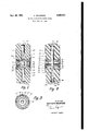
FIGURE 1 is a longitudinal section of the driving handle, some of the parts being shown in elevation;
FIGURE 2 is a complete longitudinal section of the driving handle; and
FIGURE 3 is a cross-section.
In the drawing, like reference characters indicate like elements throughout.
The driving handle is designed for obtaining a greater torque on the rotary tool than the torque imparted to that part of the handle rotated by hand, the tool rotating at a lower speed.
The driving handle of the present invention comprises identical first and second half parts 60, of substantially cylindrical shape and made of solid material, such as plastic or the like, and provided with longitudinal flutes on the outside for facilitating grasping of the handle. Half parts 60 are arranged in end-to-end relationship, but spaced apart by means of an intermediate annular sleeve 61, which slidably fits over the adjacent ends of half parts 60.
A shaft 62 extends freely within an axial bore 63 of each half part 60. The outer end of each half part 60 is provided with a central recess 64, in which the outer ends of shaft 62 protrude. Each outer end of shaft 62 is provided with an annular groove in which removably fits a lock washer 65, which abuts against a flat washer 66, in turn abutting against bottom of recess 64, thereby preventing disassembly of the two half parts 60 and longitudinal displacement of shaft 62 with respect to said half parts and to sleeve 61.
One end of shaft 62 has an extension 67 of square cross-section adapted to removably fit within a square bore of a tool adapted to be rotated by the handle of the present invention.
The opposite end of shaft 62 is provided with a square "ice recess 68, or blind bore, adapted to removably receive the square end of a rotary tool adapted to be driven by the handle. These tools are normally provided with a spring pressed ball to engage extension 67 or recess 68 to prevent accidental detachment of the tool from the handle.
A bevelled crown gear 6% is secured to the inner end of each half part 66, each crown gear 69 freely surrounding the shaft 62 and being embedded in the material of the associated half part 60. To obtain a better adhesion between the half part and the crown gear, the cylindrical face of the crown gear has corrugations 69' embedded in the plastic of the half part.
A cross shaft 70 extends through the centre of shaft 62 and is secured thereto. Bevelled pinions 71 are freely rotatably mounted on the two ends of cross shaft 70 and extend between the two crown gears 69 and are in meshing engagement therewith. The outer face of each pinion 71 is preferably convex so as to abut against sleeve 61, which retains the pinions on cross shaft 70, while allowing movement of the cross shaft and the pinions in a circular path relative to sleeve 61. Preferably, the material of the half part 60 forms lips '72, of annular shape, protruding from the outer edge of the crown gear 69 and slightly overlapping the adjacent pinions 71.
Sleeve 61 surrounds and is secured to a coupling member 73, of cylindrical shape, and provided with two opposed series of coupling tongues 74 and 75, tongues 75 being longer than tongues 74, tongues 74 and 75 being adapted to engage slots 76 and 77 respectively, made in the external surface of half parts 60 adjacent the inner ends thereof.
The longer tongues 75 are always in engagement with the notches 77 of one half part 60. In the retracted position of sleeve 61 and coupling member 73, as shown in FIGURE 1, tongues 74 clear slots 76, while tongue 75 fully engages slots 77.
As shown in FIGURE 1, upon longitudinal displacement of the sleeve 61 and coupling member 73 and by having previously rotated half part 60 provided with slots 76, so as to bring said notches in alignment with tongues 74, the latter, upon engaging slots 76, will lock the two half parts 60 to each other.
In the use of the handle in accordance with the inven tion, the square end of the stem of a nail driver, socket wrench, or the like, is fitted within square hole 68 at one end of shaft 62, or the square socket of the stem of such a rotary tool is fitted over the square extension 67 at the opposite end of shaft 62.
The handle is grasped with one hand at the half part adjacent the tool, said half part is held stationary while the opposite half part 60 is rotated by the other hand, coupling member 73 being in retracted unlocking position. Crown gear 69, secured to the half part 60 being rotated, will effect rotation of pinions 71 against the reaction member constituted by the crown gear 69 secured to the half part held stationary.
The pinions 71 will rotate shaft 62 through cross shaft 70 and, consequently, the tool is directly secured to shaft 62. During this movement, a demultiplication of the rotational speed will take place; that is, the tool will rotate at a lower speed than half part 66 being rotated by hand, thus obtaining a greater torque at the tool itself.
The two half parts 60 can be locked, as previously mentioned, by moving coupling member 73 into coupling position and, thus, the handle is used as a rigid unit, as an ordinary rotary tool handle, and no demultiplication of the rotation speed will take place.
The handle is of simple and relatively inexpensive construction because the two half-part assemblies, each consisting of half part 641 and crown gear 69, are of identical construction and shape.
The handle can be easily assembled and disassembled; for these operations, only one of the lock washers 65 needs to be inserted and removed. The handle is adaptable to several types of standard rotary tools on the market.
In the use of the handle, the operators driving hand may grasp continuously the driving half part 68 and is counterrotated with said half part at the end of its active stroke, the half part 60 being simply released and allowed to rotate during said counterrotation.
While a preferred embodiment in accordance with the present invention has been illustrated and described, it is understood that various modifications may be resorted to without departing from the spirit and scope of the appended claims.
What I claim is:
1. A driving handle for rotary tools comprising a cylindrical body made of at least first and second parts of substantially equal diameter and in end-to-end relationship, a central shaft coaxial with said body and mounted tl1erein, a cross shaft secured to said central shaft and extending on opposite sides of the latter, pinions freely rotatably mounted on said cross shaft on opposite sides of said central shaft, a first crown gear freely rotatably mounted on said central shaft and meshing with said pinions, means connecting said first crown gear wth said first body part, a second crown gear freely rotatably mounted on said central shaft and meshing with said pinions, means connecting said second body part to said second crown gear, whereby rotation of said second body part relative to said first body part will cause rotation of said central shaft at a reduced speed, means at the ends of said handle for removably connecting a rotary tool, said pinions being removable from said cross shaft, and a sleeve surrounding said pinions and slidably inserted within peripheral recesses at the adjacent end faces of said body parts, to prevent disengagement of said pinions from said cross shaft and serve as a spacer for said body parts.
2. A driving handle for rotary tools comprising a cylindrical body made of at least first and second parts of substantially equal diameter and end-to-end relationship, a central shaft coaxial with said body and mounted therein, a cross shaft secured to said central shaft and extending on opposite sides of the latter, pinions freely rotatably mounted on said cross shaft on opposite sides of said central shaft, a first crown gear freely rotatably mounted on said central shaft and meshing with said pinions, means connecting said first crown gear with said first body part, a second crown gear freely rotatably mounted on said central shaft and meshing with said pinions, means connecting said second body part to said second crown gear, whereby rotation of said second body part relative to said first body part will cause rotation of said central shaft at a reduced speed, means at the ends of said handle for removably connecting a rotary tool, the outer ends of said body parts being provided with central recesses, in which the outer ends of said central shaft protrude, and detachable retainer means mounted on said ends of said central shaft and overlapping the bottoms of the recesses of said body parts to prevent removal of said central shaft from said body parts and to retain said body parts and shaft in assembled position.
3. A driving handle for rotary tools comprising a cylindrical body made of at least first and second parts of substantially equal diameter and in end-to-end relationship, a central shaft coaxial with said body and mounted therein, a cross shaft secured to said central shaft and extending on opposite sides of the latter, pinions freely rotatably mounted on said cross shaft on opposite sides of said central shaft, a first crown gear freely rotatably mounted on said central shaft and meshing with said pinions, means connecting said first crown gear with said first body part, a second crown gear freely rotatably mounted on said central shaft and meshing with said pinions, means connecting said second body part to said second crown gear, whereby rotation of said second body part relative to said first body part will cause rotation of said central shaft at a reduced speed, means at the ends of said handle for removably connecting a rotary tool, a sleeve member surrounding the adjacent end portions of said first and second body parts and slidable with respect to the same, a cylindrical coupling member disposed between the adjacent ends of said first and second body parts, and secured to and surrounded by said sleeve member, said coupling member having oppositely directed tongues, notches made in the peripheral face of said first and second body parts at the inner ends thereof for slidably receiving said tongues to thereby lock said two body parts one to another against relative rotation, longitudinal retracting movement of said coupling member towards one of said body parts, causing the tongues of said coupling member to disengage the other body part and permit relative rotation of said other body part with respect to the first body part.
References Cited by the Examiner UNITED STATES PATENTS 2,478,935 8/49 Moritz et a1. 8l57 2,707,893 5/55 Bohnet 81-583 2,756,792 7/56 Hirschman 8l-57 X 2,879,091 3/59 Baker 287-87 3,088,338 5/63 Duchesne 8l57 X WILLIAM FELDMAN, Primary Examiner.
MILTON S. MEHR, Examiner.
Claims (1)
1. A DRIVING HANDLE FOR ROTARY TOOLS COMPRISING A CYLINDRICAL BODY MADE OF AT LEAST FIRST AND SECOND PARTS OF SUBSTANTIALLY EQUAL DIAMETER AND IN END-TO-END RELATIONSHIP, A CENTRAL SHAFT COAXIAL WITH SAID BODY AND MOUNTED THEREIN, A CROSS SHAFT SECURED TO SAID CENTRAL SHAFT AND EXTENDING A OPPOSITE SIDES OF THE LATTER, PINIONS FREELY ROTATABLE MOUNTED ON SAID CROSS SHAFT ON OPPOSITE SIDES OF SAID CENTRAL SHAFT, A FIRST CROWN GEAR FREELY ROTATABLY MOUNTED ON SAID CENTRAL SHAFT AND MESHING WITH SAID PINIONS, MEANS CONNECTING SAID FIRST CROWN GEAR WITH SAID FIRST BODY PART, A SECOND CROWN GEAR FREELY ROTATABLY MOUNTED ON SAID CENTRAL SHAFT AND MESHING WITH SAIDPINIONS, MEANS CONNECTING SAID SECOND BODY PART OF SAID SECOND CROWN GEAR, WHEREBY ROTATION OF SAID SECOND BODY PART RELATIVE TO SAID FIRST BODY PART WILL CAUSE ROTATION OF SAID CENTRAL SHAFT AT A REDUCED SPEED, MEANS AT THE ENDS OF SAID HANDLE FOR REMOVABLY CONNECTING A ROTARY TOOL, SAID PINIONS BEING REMOVABLE FROM SAID CROSS SHAFT, AND A SLEEVE SURROUNDING SAID PINIONS AND SLIDABLY INSERTED WITHIN PERIPHERAL RECESSES AT THE ADJACENT END FACES OF SAID BODY PARTS, TO PREVENT DISENGAGEMENT OF SAID PINIONS FROM SAID CROSS SHAFT AND SERVE AS A SPACER FOR SAID BODY PARTS.
Priority Applications (1)
| Application Number | Priority Date | Filing Date | Title |
|---|---|---|---|
| US346794A US3208317A (en) | 1964-02-24 | 1964-02-24 | Driving handle for rotary tools |
Applications Claiming Priority (1)
| Application Number | Priority Date | Filing Date | Title |
|---|---|---|---|
| US346794A US3208317A (en) | 1964-02-24 | 1964-02-24 | Driving handle for rotary tools |
Publications (1)
| Publication Number | Publication Date |
|---|---|
| US3208317A true US3208317A (en) | 1965-09-28 |
Family
ID=23361075
Family Applications (1)
| Application Number | Title | Priority Date | Filing Date |
|---|---|---|---|
| US346794A Expired - Lifetime US3208317A (en) | 1964-02-24 | 1964-02-24 | Driving handle for rotary tools |
Country Status (1)
| Country | Link |
|---|---|
| US (1) | US3208317A (en) |
Cited By (3)
| Publication number | Priority date | Publication date | Assignee | Title |
|---|---|---|---|---|
| DE3400116A1 (en) * | 1984-01-04 | 1985-07-11 | Erwin 7473 Straßberg Faller | ANGLE SCREW DEVICE |
| US20130239756A1 (en) * | 2012-03-15 | 2013-09-19 | Dentcraft Tools Limited Partnership | Indexable tool |
| US10022762B2 (en) | 2014-11-14 | 2018-07-17 | Dentcraft Tools Limited Partnership | Dent repair system |
Citations (5)
| Publication number | Priority date | Publication date | Assignee | Title |
|---|---|---|---|---|
| US2478935A (en) * | 1944-05-27 | 1949-08-16 | B K Sweeney Electrical Company | Gear-operated wrench |
| US2707893A (en) * | 1952-11-18 | 1955-05-10 | Bohnet Emil | Hand tool with axially movable clutch means for connecting the handle to the tool shank |
| US2756792A (en) * | 1954-07-26 | 1956-07-31 | Hirschman Jerold | Tool with speeding gear |
| US2879091A (en) * | 1955-02-15 | 1959-03-24 | Gen Motors Corp | Ball joint assembly |
| US3088338A (en) * | 1960-08-15 | 1963-05-07 | Duchesne Normand | Driver for rotary tools |
-
1964
- 1964-02-24 US US346794A patent/US3208317A/en not_active Expired - Lifetime
Patent Citations (5)
| Publication number | Priority date | Publication date | Assignee | Title |
|---|---|---|---|---|
| US2478935A (en) * | 1944-05-27 | 1949-08-16 | B K Sweeney Electrical Company | Gear-operated wrench |
| US2707893A (en) * | 1952-11-18 | 1955-05-10 | Bohnet Emil | Hand tool with axially movable clutch means for connecting the handle to the tool shank |
| US2756792A (en) * | 1954-07-26 | 1956-07-31 | Hirschman Jerold | Tool with speeding gear |
| US2879091A (en) * | 1955-02-15 | 1959-03-24 | Gen Motors Corp | Ball joint assembly |
| US3088338A (en) * | 1960-08-15 | 1963-05-07 | Duchesne Normand | Driver for rotary tools |
Cited By (4)
| Publication number | Priority date | Publication date | Assignee | Title |
|---|---|---|---|---|
| DE3400116A1 (en) * | 1984-01-04 | 1985-07-11 | Erwin 7473 Straßberg Faller | ANGLE SCREW DEVICE |
| US20130239756A1 (en) * | 2012-03-15 | 2013-09-19 | Dentcraft Tools Limited Partnership | Indexable tool |
| US8776643B2 (en) * | 2012-03-15 | 2014-07-15 | Dentcraft Tools Limited Partnership | Indexable tool |
| US10022762B2 (en) | 2014-11-14 | 2018-07-17 | Dentcraft Tools Limited Partnership | Dent repair system |
Similar Documents
| Publication | Publication Date | Title |
|---|---|---|
| TWI661909B (en) | Penetrating electric ratchet wrench and using method thereof | |
| US6070499A (en) | Ratchet wrench having two modes of reciprocating manual input | |
| US3707893A (en) | Mechanical speed ratchet | |
| US6516688B2 (en) | Hand tool | |
| US2576069A (en) | Torque-limiting wrench | |
| US9511484B2 (en) | Ratcheting screwdriver | |
| DE102011084495A1 (en) | tool attachment | |
| US10265837B2 (en) | Hand tool adapter capable of increasing output torque or rotational speed | |
| CS227006B2 (en) | Dental holder | |
| US10751860B2 (en) | Electric rapid ratchet wrench and method of using the same | |
| EP0437716B1 (en) | Electrically driven handtool | |
| US3208317A (en) | Driving handle for rotary tools | |
| US3533315A (en) | Ratchet spanner | |
| US6732613B2 (en) | Screwdriver with changeable operation modes | |
| US2989881A (en) | Multiple use hand tool having a ratchet handle | |
| AU2013374087B2 (en) | Bidirectional wrench | |
| US4265148A (en) | Ratchet tool | |
| US2477528A (en) | Variable-speed hand tool | |
| US3580097A (en) | Screw and nut driver | |
| US2607253A (en) | Clutched driving means for tools | |
| US4620459A (en) | Speed socket wrench | |
| US10974371B2 (en) | Hand tool | |
| US3214992A (en) | Tool driver attachment | |
| US2682823A (en) | Rotary cutterhead for motor cultivators | |
| US5620073A (en) | Rollerless slide switch selectable ratchet |