US3194346A - Bumper floor lock for wheeled vehicles - Google Patents
Bumper floor lock for wheeled vehicles Download PDFInfo
- Publication number
- US3194346A US3194346A US301128A US30112863A US3194346A US 3194346 A US3194346 A US 3194346A US 301128 A US301128 A US 301128A US 30112863 A US30112863 A US 30112863A US 3194346 A US3194346 A US 3194346A
- Authority
- US
- United States
- Prior art keywords
- bumper
- bar
- floor lock
- lock
- food
- Prior art date
- Legal status (The legal status is an assumption and is not a legal conclusion. Google has not performed a legal analysis and makes no representation as to the accuracy of the status listed.)
- Expired - Lifetime
Links
Images

Classifications
-
- B—PERFORMING OPERATIONS; TRANSPORTING
- B62—LAND VEHICLES FOR TRAVELLING OTHERWISE THAN ON RAILS
- B62B—HAND-PROPELLED VEHICLES, e.g. HAND CARTS OR PERAMBULATORS; SLEDGES
- B62B5/00—Accessories or details specially adapted for hand carts
- B62B5/04—Braking mechanisms; Locking devices against movement
- B62B5/049—Braking mechanisms; Locking devices against movement locking against movement by contacting the floor or a wall
Definitions
- This invention relates to a bumper floor lock and, more particularly, to a bumper floor lock for use on a wheeled vehicle such as a food service cart.
- Another object of this invention is to provide an extended bumper for the protection of the body of a vehicle, such as a food servioe cart, which bumper may be swung out of the way to provide for close positioning of two of such vehicles and, when so swung away, functions as a tioor lock to hold the vehicle in the selected location.
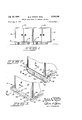
- FIG. 1 is a front elevational view, showing a pair of carts, each having a bumper embodying the invention, positioned in close end-to-end relationship, and illustrating how the bumper also functions as a floor lock;
- FIG. 2 is a fragmentary, front quarter view in perspective showing a bumper floor lock according to the instant invention in locked position;
- FIG. 3 is a fragmentary, front quarter view in perspective, similar to FIG. 2, but showing a bumper floor lock according to the instant invention in bumper position;
- FIG. 4 is a fragmentary, vertical sectional view taken along the line 44 of FIG. 3 and shown on an enlarged scale;
- FIG. 5 is a fragmentary, vertical sectional view taken along the line 5-5 of FIG. 2 and shown on an enlarged scale;
- FIG. 6 is a fragmentary, vertical sectional view taken along the line 6t5 of FIG. 4 and shown on a further enlarged scale.
- the present invention is a bumper floor lock for use on a wheeled vehicle.
- the bumper floor lock comprises a laterally extending, horizontal bumper bar.
- the bumper bar is mounted on the vehicle by a connecting structure which is fastened at one end to the bar and the other end is pivotally mounted on the vehicle for rotation between a first, or bumper position, and a second, or locked position, around an axis parallel to the bumper bar.
- Releasable means are provided for securing the bumper bar in either the locked position, as shown in FIGS. 2 and 5 or in the bumper position, as shown in FIGS. 3 and 4.
- FIG. 1 An embodiment of the invention is shown in the drawings with a bumper floor lock being generally indicated at it).
- the bumper floor lock it is illustrated as being designed for use on food service carts 11a and lib, which may be identical, as illustrated, or may be carts of different characteristics.
- the bumper floor lock can be used equally well on other types of wheeled vehicles.
- Each of the food service carts 11a and 11b has a body 12 mounted on a frame 13. Wheels 14 support the body 12 upon a surface 15, for example, a hospital corridor or factory door, or the like. A horizontal laterally extending, bumper bar 16 protrudes from the body 12 when the bumper floor lock it is in the first or bumper posi tion as shown in FIG. 3.
- the bumper bar 116 is preferably constructed with outwardly directing ribs 17 between which a resilient bumper 18 is retained.
- the bumper 18 is formed from a compressible material such as rubber, for example, by extrusion, so that any impact stresses received when the food service cart 11 collides with another object will be absorbed by the bumper 18, thereby preventing injury to the vehicle body 12 or to the other object.
- a pair of dowels 25 and 26 is secured to each of the pivot plates 23 and 2d and, in the instant embodiment, to an end portion 27 or 28 of the bumper bar 16.
- the rearward dowel 26 extends through an elongated hole 29 in a hinge plate 3i
- Each of the hinge Plates 30 is secured to a side member of the frame 13 by rivets 32.
- the connecting structure 19 is therefore pivotally mounted for rotation around a laterally extending horizontal axis.
- the axis of rotation is parallel to a main portion 33 of the bumper bar 16.
- the axis of rotation extends transversely across the body 12 and in the instant embodiment is located by the elongated holes 29.
- the hinge plates 3% lie between the pivot plates 23 or 24 and the end portions 27 or 23 of the bumper bar 16.
- Each of the hinge plates 3t? has a dowel-engaging recess 34 formed in one end.
- the end of the hinge plate 3t? also has a dowel stop 35.
- each of the tension springs 36 is secured to an eye-bolt 37 which is fastened to the transverse support bar 20 and the other end is connected to an eye-bolt 38 which is secured to a horizontal, transversely-extending reinforcing bar 39 which is an integral part of the frame 13.
- the springs 36 retain the dowels 25 against the dowel stops 35 at the ends of the plates 30.
- V bumper bar 16 reaches the second or l-ocked position
- the dowels 25 engage the dowel stops 35 to prevent further counterclockwise rotation.
- Tension of. the springs 36 swings the bar 16 and connecting structure 19 so that the dowels 26 shift to thetouter ends of the elongated holes 29 carrying the structure over center.
- the length of the connecting structure 19 is suchthat the distance from the longitudinal axis of rotation to the food service cart 11 from moving under the force ofgravity or under the force of an accidental bumping.
- the tension spring's'36 restrain the bumper bar 16 against movement in a clockwise direction from its 'locked, over-center position.
- the tension springs 36 retain the bumper floor lock 7 It) in thisposition which is the first or bumper posit-ion, 1 i
- a bumperfioor'lock for use on a wheeled vehicle. having a vehicle body and a set of wheels for'supportingsaid body on a surface, said necting structure, fastened at a first endto said bumper bar, means for pivotally mounting a second end of said connecting structure for rotation, between ta'first position and a second position around an axisparallel to. said bumper bar, said' axis being so positioned relativetto said body and thelength of-said connecting structurebeing such: 7 that said bumper bar protrudes horizontallybeyond said, vehicle bodywhen insaid firstaposition, and the distance from said axis t'olthe outer edge of said bumper bar being greater than the distance from said axis to said surface,
- said pivotallymountingTmeans comprising, a hinge plate extending from said vehicle? body and'defin' ing on its outer edge an/engaging recess'and a spaced apart stop, said second end of said connecting-structure being pivotally mounted to said hingeplateand having an engaging member which is releasably seatedin'said engaging recess when said bumper bar is in saidrfirst position a and is adjacent'said stop when said bumper bar isinlsaid first and second positions.
- a bumper bar floor lock' according to claim 1 Whichrsaid releasable means includes a tension spring operably connected at opposite ends to said vehicle body and said connecting structure, whereby said, bumper-bar and connecting structures are releasably secured undertonsion when said bum-per bar andconnec'ting structures are located. in eithen of said first and second positions.
- bumpenfloor lock gcornp'risw mg a laterally extending, horizontal bumperbar, a coni
Description
BUMPER FLOOR LOCK FOR WHEELED VEHICLES Filed Aug. 9, 1963 2 Sheets-Sheet 1 INVENTORS. BLAuz E. STENTZ AMES VAUGHT BY E faxh
y 1965 B. E. STENTZ ETAL 3,194,346
BUMPER FLOOR LOOK FOR WHEELED VEHICLES Filed Aug. 9, 1963 2 Sheets-Sheet 2 1 VENTORS. BLAJR E. TENTZ. .JAMEs E. VAUGHT 51 EM QM ATTORNEYS United States Patent FLOGFL LOCK FUR WHEELED VEHlCLES Blair E. Stentz and lenses E. Vaught, Murfreeshoro,
Tenn, assignors to United Service Equipment Co., Inc,
Palmer, Mass, a corporation of Delaware Filed Aug. 9, 1963, Ser. No. 301,128 3 Claims. (Cl. 188-5) This invention relates to a bumper floor lock and, more particularly, to a bumper floor lock for use on a wheeled vehicle such as a food service cart.
When food service car-ts are used in a large food handling and serving operation, for example, at a factory, several food service carts are normally used in the operation. For example, one cart is loaded with utensils, another with food trays, another with beverage containers, and one or more with bulk food. Of course, the number of food service carts involved depends upon the size of the food serving operation. The food service carts are transported to a central area or cafeteria area of the factory and placed in their respective locations in the food service operation.
If no braking device is provided on the individual food service car-t, an accidental bumping of the cart will move the cart from its stationary position in the food serving operation thereby disrupting said operation. Also, when the utensils or food items are being removed from the individual food service carts, it is important that the cart remain in a stationary position.
Another problem encountered in a food handling operation is that the service carts, which are often constructed of stainless steel or aluminum, become marred or dented upon impact with, for example, a wall of a factory corridor or another service cart.
in order to protect such a cart from impact, it is conventional to provide a bumper which protrudes beyond the body of the cart and which usually has a resilient or shock absorbing surface. Such protruding bumpers prevent such carts from being positioned in close adjacency as would be preferable in a cafeteria arrangement, as earlier described;
It is the object of the present invention to provide a bumper for a wheeled vehicle, for example a food service cart, which can be swung out of the way to provide for positioning two such vehicles in close end-to-end adjacency.
Another object of this invention is to provide an extended bumper for the protection of the body of a vehicle, such as a food servioe cart, which bumper may be swung out of the way to provide for close positioning of two of such vehicles and, when so swung away, functions as a tioor lock to hold the vehicle in the selected location.
Further objects of this invention will become apparent from the following specification and drawings, in which:
FIG. 1 is a front elevational view, showing a pair of carts, each having a bumper embodying the invention, positioned in close end-to-end relationship, and illustrating how the bumper also functions as a floor lock;
FIG. 2 is a fragmentary, front quarter view in perspective showing a bumper floor lock according to the instant invention in locked position;
FIG. 3 is a fragmentary, front quarter view in perspective, similar to FIG. 2, but showing a bumper floor lock according to the instant invention in bumper position;
FIG. 4 is a fragmentary, vertical sectional view taken along the line 44 of FIG. 3 and shown on an enlarged scale;
FIG. 5 is a fragmentary, vertical sectional view taken along the line 5-5 of FIG. 2 and shown on an enlarged scale; and
Biddfidfi Patented duly 13, 1965 "ice FIG. 6 is a fragmentary, vertical sectional view taken along the line 6t5 of FIG. 4 and shown on a further enlarged scale.
Briefly, the present invention is a bumper floor lock for use on a wheeled vehicle. The bumper floor lock comprises a laterally extending, horizontal bumper bar. The bumper bar is mounted on the vehicle by a connecting structure which is fastened at one end to the bar and the other end is pivotally mounted on the vehicle for rotation between a first, or bumper position, and a second, or locked position, around an axis parallel to the bumper bar. Releasable means are provided for securing the bumper bar in either the locked position, as shown in FIGS. 2 and 5 or in the bumper position, as shown in FIGS. 3 and 4.
An embodiment of the invention is shown in the drawings with a bumper floor lock being generally indicated at it). In FIG. 1, the bumper floor lock it) is illustrated as being designed for use on food service carts 11a and lib, which may be identical, as illustrated, or may be carts of different characteristics. Of course, the bumper floor lock can be used equally well on other types of wheeled vehicles.
Each of the food service carts 11a and 11b has a body 12 mounted on a frame 13. Wheels 14 support the body 12 upon a surface 15, for example, a hospital corridor or factory door, or the like. A horizontal laterally extending, bumper bar 16 protrudes from the body 12 when the bumper floor lock it is in the first or bumper posi tion as shown in FIG. 3.
As shown in FIG. 6, the bumper bar 116 is preferably constructed with outwardly directing ribs 17 between which a resilient bumper 18 is retained. The bumper 18 is formed from a compressible material such as rubber, for example, by extrusion, so that any impact stresses received when the food service cart 11 collides with another object will be absorbed by the bumper 18, thereby preventing injury to the vehicle body 12 or to the other object.
A connecting structure generally indicated at 19 and comprising a transverse support bar 2%), reinforcing bars 21 and Z2, and pivot plates 23 and 24, is welded, or otherwise suitably fastened to the bumper bar 16.
Referring to FIGS. 4 and 6, a pair of dowels 25 and 26 is secured to each of the pivot plates 23 and 2d and, in the instant embodiment, to an end portion 27 or 28 of the bumper bar 16. The rearward dowel 26 extends through an elongated hole 29 in a hinge plate 3i Each of the hinge Plates 30 is secured to a side member of the frame 13 by rivets 32.
The connecting structure 19 is therefore pivotally mounted for rotation around a laterally extending horizontal axis. The axis of rotation is parallel to a main portion 33 of the bumper bar 16. The axis of rotation extends transversely across the body 12 and in the instant embodiment is located by the elongated holes 29.
As shown in FIGS. 4, 5 and 6, the hinge plates 3% lie between the pivot plates 23 or 24 and the end portions 27 or 23 of the bumper bar 16. Each of the hinge plates 3t? has a dowel-engaging recess 34 formed in one end. The end of the hinge plate 3t? also has a dowel stop 35. When the bumper lock 10 is in the first or bumper position, the dowels 25 are releasably retained in the recesses 34 by means of a pair of tension springs 36. One end of each of the tension springs 36 is secured to an eye-bolt 37 which is fastened to the transverse support bar 20 and the other end is connected to an eye-bolt 38 which is secured to a horizontal, transversely-extending reinforcing bar 39 which is an integral part of the frame 13. When the bumper floor lock 10 is in the second or locked position, the springs 36 retain the dowels 25 against the dowel stops 35 at the ends of the plates 30.
When it is desired to move the bumper floor lock 10 from the bumper position (FIG. 4) to thesecond or locked position (FIG. 5), a downward pressure is applied by the operator, for example with his foot, on the bumper bar 16, at approximately point P in FIG. 4. When the force applied at point P exceeds that of the tension springs 36, the dowels 25 are moved out of the dowelengaging recesses 34 and the bumper bar 16 is rotated.
downwardly in a counterclockwisedirection. 'When the" V bumper bar 16 reaches the second or l-ocked position,
shown in FIG. 5, the dowels 25 engage the dowel stops 35 to prevent further counterclockwise rotation. Tension of. the springs 36 swings the bar 16 and connecting structure 19 so that the dowels 26 shift to thetouter ends of the elongated holes 29 carrying the structure over center.
The length of the connecting structure 19 is suchthat the distance from the longitudinal axis of rotation to the food service cart 11 from moving under the force ofgravity or under the force of an accidental bumping.
The tension spring's'36 restrain the bumper bar 16 against movement in a clockwise direction from its 'locked, over-center position.
When it is desired to move the food service cart 11, V and the bumper fi-oor lock 10 is in the second or locked position shown in FIG. 5, the operator applies pressure with his foot, or otherwise, on the bumper bar 16, for 7 example at point P as. shown in FIG. '5. The dowels 261 are shifted tothe rear of the elongated holes 29, and the dowels 25 moved from their positions against the dowel stops 35 and slide up into the dowel-engaging recesses;
' second position, and releasablefmeans for biasing said bumper barand said connecting structure in eitherof said 34. The tension springs 36 retain the bumper floor lock 7 It) in thisposition which is the first or bumper posit-ion, 1 i
While the invention'has been disclosed; in conjunction with a specific form and disposition of the parts, it should be expressly understood that numerous modifications and changes may be made without departing fronr the spirit and scope of the appended claims.
What we claim is:
:1. A bumperfioor'lock, for use on a wheeled vehicle. having a vehicle body and a set of wheels for'supportingsaid body on a surface, said necting structure, fastened at a first endto said bumper bar, means for pivotally mounting a second end of said connecting structure for rotation, between ta'first position and a second position around an axisparallel to. said bumper bar, said' axis being so positioned relativetto said body and thelength of-said connecting structurebeing such: 7 that said bumper bar protrudes horizontallybeyond said, vehicle bodywhen insaid firstaposition, and the distance from said axis t'olthe outer edge of said bumper bar being greater than the distance from said axis to said surface,
whereby :at least one of said wheels iselevated from said surface when said bumper, bar ,is rotat'eddownwardly into said'second positiont and into engagement with said surface, said pivotallymountingTmeans, comprising, a hinge plate extending from said vehicle? body and'defin' ing on its outer edge an/engaging recess'and a spaced apart stop, said second end of said connecting-structure being pivotally mounted to said hingeplateand having an engaging member which is releasably seatedin'said engaging recess when said bumper bar is in saidrfirst position a and is adjacent'said stop when said bumper bar isinlsaid first and second positions.
2. A bumper bar floor lock' according to claim 1 Whichrsaid releasable means includes a tension spring operably connected at opposite ends to said vehicle body and said connecting structure, whereby said, bumper-bar and connecting structures are releasably secured undertonsion when said bum-per bar andconnec'ting structures are located. in eithen of said first and second positions.
3. A bumper floor lock according to ,claimfl wherein said hinge plate defines a horizontally elongate ;pivot opening and a pivot dowelon said second endfof said connecting structure slidablyiand pivotally mounted with in such opening. V V 7 References Cited by. 'theEXaminer,
UNITED STATES PATENTS ARTHUR L. LA POINT, Primary Ex'antine DUANE A. REGER, Examiner. I
bumpenfloor lock gcornp'risw, mg a laterally extending, horizontal bumperbar, a coni
Priority Applications (1)
| Application Number | Priority Date | Filing Date | Title |
|---|---|---|---|
| US301128A US3194346A (en) | 1963-08-09 | 1963-08-09 | Bumper floor lock for wheeled vehicles |
Applications Claiming Priority (1)
| Application Number | Priority Date | Filing Date | Title |
|---|---|---|---|
| US301128A US3194346A (en) | 1963-08-09 | 1963-08-09 | Bumper floor lock for wheeled vehicles |
Publications (1)
| Publication Number | Publication Date |
|---|---|
| US3194346A true US3194346A (en) | 1965-07-13 |
Family
ID=23162071
Family Applications (1)
| Application Number | Title | Priority Date | Filing Date |
|---|---|---|---|
| US301128A Expired - Lifetime US3194346A (en) | 1963-08-09 | 1963-08-09 | Bumper floor lock for wheeled vehicles |
Country Status (1)
| Country | Link |
|---|---|
| US (1) | US3194346A (en) |
Cited By (5)
| Publication number | Priority date | Publication date | Assignee | Title |
|---|---|---|---|---|
| US3664464A (en) * | 1970-06-24 | 1972-05-23 | Lockheed Aircraft Corp | Antiskid device |
| US5417300A (en) * | 1991-06-27 | 1995-05-23 | Shultz; Richard E. | Compact stackable vehicle |
| WO2007028194A1 (en) | 2005-09-05 | 2007-03-15 | Checkmate International Pty Ltd | Apparatus for transporting products in crates or containers |
| AU2006289649B2 (en) * | 2005-09-05 | 2011-02-10 | Checkmate International Pty Ltd | Apparatus for transporting products in crates or containers |
| US20210370839A1 (en) * | 2020-02-07 | 2021-12-02 | Richard Mellick Zock | Adjustable grab bar for utility vehicles and associable carrying rack |
Citations (4)
| Publication number | Priority date | Publication date | Assignee | Title |
|---|---|---|---|---|
| US2054838A (en) * | 1934-06-23 | 1936-09-22 | Gen Spring Bumper Corp | Bead construction for bumpers |
| US2789854A (en) * | 1952-03-10 | 1957-04-23 | Hope James | Swing-jack space-guard |
| US2812041A (en) * | 1953-08-10 | 1957-11-05 | Rol Fol Table Inc | Roller brake |
| US2886139A (en) * | 1957-08-01 | 1959-05-12 | Reid F Wilson | Auxiliary vehicle brake |
-
1963
- 1963-08-09 US US301128A patent/US3194346A/en not_active Expired - Lifetime
Patent Citations (4)
| Publication number | Priority date | Publication date | Assignee | Title |
|---|---|---|---|---|
| US2054838A (en) * | 1934-06-23 | 1936-09-22 | Gen Spring Bumper Corp | Bead construction for bumpers |
| US2789854A (en) * | 1952-03-10 | 1957-04-23 | Hope James | Swing-jack space-guard |
| US2812041A (en) * | 1953-08-10 | 1957-11-05 | Rol Fol Table Inc | Roller brake |
| US2886139A (en) * | 1957-08-01 | 1959-05-12 | Reid F Wilson | Auxiliary vehicle brake |
Cited By (10)
| Publication number | Priority date | Publication date | Assignee | Title |
|---|---|---|---|---|
| US3664464A (en) * | 1970-06-24 | 1972-05-23 | Lockheed Aircraft Corp | Antiskid device |
| US5417300A (en) * | 1991-06-27 | 1995-05-23 | Shultz; Richard E. | Compact stackable vehicle |
| WO2007028194A1 (en) | 2005-09-05 | 2007-03-15 | Checkmate International Pty Ltd | Apparatus for transporting products in crates or containers |
| EP1931552A1 (en) * | 2005-09-05 | 2008-06-18 | Checkmate International PTY LTD | Apparatus for transporting products in crates or containers |
| EP1931552A4 (en) * | 2005-09-05 | 2008-09-03 | Checkmate Internat Pty Ltd | Apparatus for transporting products in crates or containers |
| US20080315537A1 (en) * | 2005-09-05 | 2008-12-25 | Checkmate International Pty Ltd | Apparatus for Transporting Products in Crates or Containers |
| AU2006289649B2 (en) * | 2005-09-05 | 2011-02-10 | Checkmate International Pty Ltd | Apparatus for transporting products in crates or containers |
| US7891675B2 (en) | 2005-09-05 | 2011-02-22 | Checkmate International Pty Ltd. | Apparatus for transporting products in crates or containers |
| US20210370839A1 (en) * | 2020-02-07 | 2021-12-02 | Richard Mellick Zock | Adjustable grab bar for utility vehicles and associable carrying rack |
| US11618389B2 (en) * | 2020-02-07 | 2023-04-04 | Richard Mellick Zock | Adjustable grab bar for utility vehicles and associable carrying rack |
Similar Documents
| Publication | Publication Date | Title |
|---|---|---|
| US6099220A (en) | Cart lock | |
| US4772165A (en) | Load restraining apparatus for vehicles | |
| US2974931A (en) | Load holder | |
| US2094401A (en) | Deck loader and unloader | |
| US4203609A (en) | Transport vehicle | |
| US20170217358A1 (en) | Removable cart assembly for vehicles | |
| US6074143A (en) | Adjustable decking system for supporting freight | |
| US9969317B2 (en) | Multi-application vehicular retention system | |
| US3140850A (en) | Vehicle tie down apparatus | |
| US3194346A (en) | Bumper floor lock for wheeled vehicles | |
| US3307658A (en) | Brake apparatus for carts | |
| US3338423A (en) | Cargo transporting device | |
| US20060170234A1 (en) | Bed max | |
| US2593174A (en) | Permanent dunnage | |
| US2978993A (en) | Attachment for railroad flat car | |
| CA2076880C (en) | Pallet return pallet rack system | |
| US2895569A (en) | Safety car block | |
| US3193123A (en) | Utility truck | |
| US3224787A (en) | Nestable industrial cart | |
| US2809755A (en) | Saddle rack for horse trailers | |
| US3472332A (en) | Combination impact cushioning bumper and automatic roadway brake | |
| US3413932A (en) | Bulkhead | |
| US3472180A (en) | Side filler | |
| US2339646A (en) | Detachable handle for trucks | |
| US2894462A (en) | Longitudinally shiftable bulkheads for freight cars |