US3180666A - Door stop - Google Patents
Door stop Download PDFInfo
- Publication number
- US3180666A US3180666A US198051A US19805162A US3180666A US 3180666 A US3180666 A US 3180666A US 198051 A US198051 A US 198051A US 19805162 A US19805162 A US 19805162A US 3180666 A US3180666 A US 3180666A
- Authority
- US
- United States
- Prior art keywords
- door
- wall
- head
- ridges
- stop member
- Prior art date
- Legal status (The legal status is an assumption and is not a legal conclusion. Google has not performed a legal analysis and makes no representation as to the accuracy of the status listed.)
- Expired - Lifetime
Links
Images

Classifications
-
- E—FIXED CONSTRUCTIONS
- E05—LOCKS; KEYS; WINDOW OR DOOR FITTINGS; SAFES
- E05C—BOLTS OR FASTENING DEVICES FOR WINGS, SPECIALLY FOR DOORS OR WINDOWS
- E05C17/00—Devices for holding wings open; Devices for limiting opening of wings or for holding wings open by a movable member extending between frame and wing; Braking devices, stops or buffers, combined therewith
- E05C17/02—Devices for holding wings open; Devices for limiting opening of wings or for holding wings open by a movable member extending between frame and wing; Braking devices, stops or buffers, combined therewith by mechanical means
- E05C17/46—Devices for holding wings open; Devices for limiting opening of wings or for holding wings open by a movable member extending between frame and wing; Braking devices, stops or buffers, combined therewith by mechanical means in which the wing or a member fixed thereon is engaged by a movable fastening member in a fixed position; in which a movable fastening member mounted on the wing engages a stationary member
- E05C17/52—Devices for holding wings open; Devices for limiting opening of wings or for holding wings open by a movable member extending between frame and wing; Braking devices, stops or buffers, combined therewith by mechanical means in which the wing or a member fixed thereon is engaged by a movable fastening member in a fixed position; in which a movable fastening member mounted on the wing engages a stationary member comprising a snap, catch, or the like
-
- Y—GENERAL TAGGING OF NEW TECHNOLOGICAL DEVELOPMENTS; GENERAL TAGGING OF CROSS-SECTIONAL TECHNOLOGIES SPANNING OVER SEVERAL SECTIONS OF THE IPC; TECHNICAL SUBJECTS COVERED BY FORMER USPC CROSS-REFERENCE ART COLLECTIONS [XRACs] AND DIGESTS
- Y10—TECHNICAL SUBJECTS COVERED BY FORMER USPC
- Y10T—TECHNICAL SUBJECTS COVERED BY FORMER US CLASSIFICATION
- Y10T292/00—Closure fasteners
- Y10T292/08—Bolts
- Y10T292/0876—Double acting
-
- Y—GENERAL TAGGING OF NEW TECHNOLOGICAL DEVELOPMENTS; GENERAL TAGGING OF CROSS-SECTIONAL TECHNOLOGIES SPANNING OVER SEVERAL SECTIONS OF THE IPC; TECHNICAL SUBJECTS COVERED BY FORMER USPC CROSS-REFERENCE ART COLLECTIONS [XRACs] AND DIGESTS
- Y10—TECHNICAL SUBJECTS COVERED BY FORMER USPC
- Y10T—TECHNICAL SUBJECTS COVERED BY FORMER US CLASSIFICATION
- Y10T403/00—Joints and connections
- Y10T403/32—Articulated members
- Y10T403/32114—Articulated members including static joint
- Y10T403/32131—One member is plate or side
- Y10T403/32155—Bearing component clamped to plate or side, e.g., bolted, etc.
-
- Y—GENERAL TAGGING OF NEW TECHNOLOGICAL DEVELOPMENTS; GENERAL TAGGING OF CROSS-SECTIONAL TECHNOLOGIES SPANNING OVER SEVERAL SECTIONS OF THE IPC; TECHNICAL SUBJECTS COVERED BY FORMER USPC CROSS-REFERENCE ART COLLECTIONS [XRACs] AND DIGESTS
- Y10—TECHNICAL SUBJECTS COVERED BY FORMER USPC
- Y10T—TECHNICAL SUBJECTS COVERED BY FORMER US CLASSIFICATION
- Y10T403/00—Joints and connections
- Y10T403/32—Articulated members
- Y10T403/32254—Lockable at fixed position
- Y10T403/32262—At selected angle
- Y10T403/32311—Ball and socket
-
- Y—GENERAL TAGGING OF NEW TECHNOLOGICAL DEVELOPMENTS; GENERAL TAGGING OF CROSS-SECTIONAL TECHNOLOGIES SPANNING OVER SEVERAL SECTIONS OF THE IPC; TECHNICAL SUBJECTS COVERED BY FORMER USPC CROSS-REFERENCE ART COLLECTIONS [XRACs] AND DIGESTS
- Y10—TECHNICAL SUBJECTS COVERED BY FORMER USPC
- Y10T—TECHNICAL SUBJECTS COVERED BY FORMER US CLASSIFICATION
- Y10T403/00—Joints and connections
- Y10T403/49—Member deformed in situ
- Y10T403/4966—Deformation occurs simultaneously with assembly
Definitions
- This invention relates to door stops and to combined door stopping and holding means, one object of the invention being to provide an improved device of this character comprising a laterally flexible coiled spring means for engagement between a door and wall, with means for adjusting and securing the angle of incidence between such spring means and the door or wall into engagement with which it is moved, to thereby insure properly aligned coincident engagement of the parts.
- Door hinge axes are oifset at varying distances from their frames and so occupy varying angular relations with an adjacent wall when moved to open position. Furthermore, the baseboard of such wall is commonly curved or inclined to the vertical.
- a further object, more specifically stated, is to provide a swiveling mounting for the spring means of the door stop, to secure its perpendicular incidence with the door or wall into engagement with which it is moved and accurate registry of the respective holding parts which may be employed.
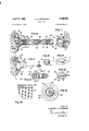
- FIG. 1 is a top plan view of parts of a door stop means for mounting 011 a wall or door, illustrating the flexibility of the same;
- FIG. 2 is a fragmentary view of parts shown in FIG. 1 as adjusted for marking the position of a cooperating part on a door or wall;
- FIG. 3 is an end view of parts shown in FIG. 1 as viewed from the left;
- FIG. 4 is a top plan view of a holding part for attachment to a door or wall for cooperating with the parts of FIG. 1;
- FIG. 5 is an end view of the parts shown in MG. 4 viewed from the left; I
- PEG. 6 is a sectional view of the parts shown in FIG. 1 on the line tZ-d in FIG. 3;
- FIG. 7 is a sectional view on the line 7-7 in FIG. 5;
- FIG. 8 is an end view of parts shown in FIG. 6 for limitin extension of the s rin means thereof;
- FIG. 12 is an enlarged end view of parts shown in FIG. 11 as viewed from the left;
- FIG. 13 is an enlarged, sectional view of parts shown in FIG. 11, and I FIG. 14 is an enlarged, fragmentary view of part of the spring means shown in FIG. 6.
- the present invention provides a door stop comprising a flexible, coiled wire spring means for attachment to a door or Wall and to the combination thereof with means for attachment to a door or wall for releasably holding a door in open position.
- the embodiment of the invention shown in FlGS. l to 6, inclusive comprises a mounting part 26 having wings or ends 22 formed with openings, as 24-, for the reception of screws in for securing a flat base of the part to a wall or door, it being understood that the door stop is adapted for mounting on either one of a wall or door for cooperation with the other.
- Mounting part 2% may be molded of plastic or metal and formed through its base with a recess 23 having an arcuate shape extending endwise of base 2%, as shown, the other sides 39 of the recess being perpendicular to the plane of the base.
- the recess is formed at its bottom with an opening 32 for the extension therethrough of the spring means of the stop and the arcuate walls of the recess are preferably formed with small grippingv ridges 34 for a purpose hereafter described.
- the laterally flexible coiled spring means comprises a coiled portion 36 wound under tension with adjacent coils in contact with each other. One end of this coil is tightly fitted, as by rotation in the direction of winding, to the outside of the reduced portion 38 of a mounting element tl having arcuate ends 42, this element having a shape conforming to that of the recess in part 2%, so that it has a horizontal swiveling or pivotal adjustment in such recess.
- Element 4% has a substantially arcuate enlargement 44 formed with small transverse gripping ridges, as shown, for engagement with the wall or door, to lock the part do in adjusted position in the recess of part 20 when its screws as are tightened home.
- Enlargement 44 is formed centrally with an opening or bore 46 extending in varying shape through the other end of part The outer end of bore as is cylindrical and a sleeve 48 is inserted therein for a purpose hereafter described.
- Fart 4a is formed inwardly of bore as with a portion fill of hexagonal shape for the sliding reception of a hexagonal head 52 (FIGS. 8, 9 and 10).
- Head 52 is formed with a slotted end 54 and with a central opening 56 for the reception of one end of a flexible anchoring wire 53 having its extremity looped, as at so, to lit in slot 54 and hold the wire against turning.
- Sleeve has an internal diameter smaller than the head and is driven and frictionally secured in the opening 46 of part so, to limit the movement of head 52 in one direction.
- the other end of head 52 bears against a short coiled spring as between it and an inwardly shouldered portion at the inner end of part at, to allow a limited movement of the head in its bore and of wire 58, as hereafter referred to.
- Wire 58 extends from head 52 through spring 62 and an opening in the inner end of part as, with its other end fixed in a threaded plug 64, hereafter referred to.
- the outer end of coil as has molded or threaded thereon a plastic or metal sleeve 76 (FIG. 6) with an enlarged and cone-shaped end 72 for engagement with a cooperating holding part on a door or wall.
- a stud "74 has a threaded end 76 adjustably threaded in and with the coils of rigid coil es.
- the outer end of stud 74 is slotted, as shown, for engagement by a screwdriver to turn it in coil 66 and so adjust its degree of projection beyond the outer end of sleeve to, to limit the degree of entry of sleeve cone '72 into the coacting holding part (FIG. 7) on the door or wall.
- the inner end of stud 74 is also formed with a small central point '73 adapted to be posiits bottom for reception of a screw 84 for securing its fiat base against the surface of a door or wall.
- the part 8% is thus formed with a relatively thin rim indented by With the stud in this spaced slots 85 to afford some yielding expansion during 7 entry of the cone 72 of sleeve 70 of the spring means.
- Cone 72 terminates at its larger end in a shoulder 86 which engages within the rim of part 8%) to releasably hold these parts in engagement with each other and hold the door in open position.
- part 26 for attachment to the wall or door described above is replaced by a part 953 of circular shape having a plurality of openings for screws 92 for securing its fiat bottom to the surface of the Wall or door.
- Part fill is formed with a recess Q4 which, instead of being arcuate as above, is of spherical shape, with a plurality of low circular gripping ridges 96.
- An opening 93 through the bottom of the recess loosely receives the reduced portion 16b of a mounting element 1'82 of spherical shape conform.- ing to and fitting in the recess of part 90.
- Element 152 and its portion res have a central opening therethrough enlarged at one end to receive and frictionally retain a button 194 having a projecting outer end formed with small concentric gripping ridges 1% adapted to slightly indent and frictionally grip the surface of the Wall or door when the screws 92 are turned home to tighten part 90 against the wall or door surface, thus securing body ms in adjusted angular position in the recess of part an, assisted by the frictional resistance afforded by the ridges 96.
- the central opening through element 162 is formed adjacent its other end with a hexagonal shape in which a hexagonal head 1% is slidably received and held against parts being thesarne as described above in connection with the first modification, including a plug similar to stud 74 of the first modification.
- the invention thus provides a stop of flexible coil spring type, adapted to yield under contact with a foot or other object.
- Such spring means is mounted for swiveling adjustment ofv its position, laterally in the modification of FIG. 6'or universally in the modification of FIG. 11, as desirable, to accommodate mounting on curved base parts of Walls or varying distances of door hinge axes from their frames, thus introducing angular variance between a door and the base part of a wall.
- the spring means With the spring means adjusted for perpendicular incidence with the door, the latter is. conveniently marked for location of the cooperating holding part, and plug 74 provides adjustment of the degree of releasing resistance of cone 72 With the recess of part 8-23.
- the invention thus provides a stop or stop and holding mechanism convenient to mount for use andconveniently adjustable in its several'parts for adaptation to the particular conditions ofits installation, as well as for varying the force desired for door holding and release.
- a door stop assembly for attachment to a substantially planiform mounting surface of Wood material or the like comprising a door stop member including an axially elongated, laterally flexible, coiled wire spring having outer and rear ends to be respectively disposed remote from and adjacent to said surface, a buffer head on said outer end for contacting .a relatively movable object to be stopped, and a swivel base formation fixed to the rear end of said springincluding surface portions of convex arcuatecross-section substantiallycentered about the longitudinal axis of said spring facing generally toward said outer'end and a rearwardly projecting locking head of substantially semicircular cross-section to engage 'said surface when said door stop member is mounted thereon, said locking head having a plurality of surface penetrating sharp ridges projecting rearwardly therefrom at positions spaced different radial distances from an extension of said axis, said ridges being formed of a material of sufficient hardness to bite into said surface, a mounting base member having an apertured socket receiving said swivel base
Landscapes
- Engineering & Computer Science (AREA)
- Mechanical Engineering (AREA)
- Closing And Opening Devices For Wings, And Checks For Wings (AREA)
Description
April 27, 1965 Filed ma 28, 1962 III] FIG. I
C. H. JORGENSEN DOOR STOP 2 Sheets-Sheet 1 FIG. 4
INVENTOR. CLARENCE H. JORGENSEN BY W4 9 ATTORNEYS P" 1965 c. H. JORGENSEN 3,180,666
DOOR STOP Filed May 28, 1962 2 SheetsShe et..2
FIG. l4'
INVENTOR.
CLARENCE H. JORGENSEN ATTORNEYS United States Patent 3,l%@,% Patented Apr. 2?, i965 This invention relates to door stops and to combined door stopping and holding means, one object of the invention being to provide an improved device of this character comprising a laterally flexible coiled spring means for engagement between a door and wall, with means for adjusting and securing the angle of incidence between such spring means and the door or wall into engagement with which it is moved, to thereby insure properly aligned coincident engagement of the parts.
Door hinge axes are oifset at varying distances from their frames and so occupy varying angular relations with an adjacent wall when moved to open position. Furthermore, the baseboard of such wall is commonly curved or inclined to the vertical. A further object, more specifically stated, is to provide a swiveling mounting for the spring means of the door stop, to secure its perpendicular incidence with the door or wall into engagement with which it is moved and accurate registry of the respective holding parts which may be employed.
To these and other ends the invention resides in certain improvements and combinations of parts, all as will be hereinafter more fully described, the novel features being pointed out in the claims at the end of the specification.
In the drawings:
- FIG. 1 is a top plan view of parts of a door stop means for mounting 011 a wall or door, illustrating the flexibility of the same;
FIG. 2 is a fragmentary view of parts shown in FIG. 1 as adjusted for marking the position of a cooperating part on a door or wall;
FIG. 3 is an end view of parts shown in FIG. 1 as viewed from the left;
FIG. 4 is a top plan view of a holding part for attachment to a door or wall for cooperating with the parts of FIG. 1;
FIG. 5 is an end view of the parts shown in MG. 4 viewed from the left; I
PEG. 6 is a sectional view of the parts shown in FIG. 1 on the line tZ-d in FIG. 3;
FIG. 7 is a sectional view on the line 7-7 in FIG. 5;
FIG. 8 is an end view of parts shown in FIG. 6 for limitin extension of the s rin means thereof;
of parts shown in PEG. 6;
FIG. 12 is an enlarged end view of parts shown in FIG. 11 as viewed from the left;
PEG. 13 is an enlarged, sectional view of parts shown in FIG. 11, and I FIG. 14 is an enlarged, fragmentary view of part of the spring means shown in FIG. 6.
The present invention provides a door stop comprising a flexible, coiled wire spring means for attachment to a door or Wall and to the combination thereof with means for attachment to a door or wall for releasably holding a door in open position. The embodiment of the invention shown in FlGS. l to 6, inclusive, comprises a mounting part 26 having wings or ends 22 formed with openings, as 24-, for the reception of screws in for securing a flat base of the part to a wall or door, it being understood that the door stop is adapted for mounting on either one of a wall or door for cooperation with the other. I
Mounting part 2% may be molded of plastic or metal and formed through its base with a recess 23 having an arcuate shape extending endwise of base 2%, as shown, the other sides 39 of the recess being perpendicular to the plane of the base. The recess is formed at its bottom with an opening 32 for the extension therethrough of the spring means of the stop and the arcuate walls of the recess are preferably formed with small grippingv ridges 34 for a purpose hereafter described.
The laterally flexible coiled spring means comprises a coiled portion 36 wound under tension with adjacent coils in contact with each other. One end of this coil is tightly fitted, as by rotation in the direction of winding, to the outside of the reduced portion 38 of a mounting element tl having arcuate ends 42, this element having a shape conforming to that of the recess in part 2%, so that it has a horizontal swiveling or pivotal adjustment in such recess. Element 4% has a substantially arcuate enlargement 44 formed with small transverse gripping ridges, as shown, for engagement with the wall or door, to lock the part do in adjusted position in the recess of part 20 when its screws as are tightened home. Enlargement 44; is formed centrally with an opening or bore 46 extending in varying shape through the other end of part The outer end of bore as is cylindrical and a sleeve 48 is inserted therein for a purpose hereafter described.
Fart 4a is formed inwardly of bore as with a portion fill of hexagonal shape for the sliding reception of a hexagonal head 52 (FIGS. 8, 9 and 10). Head 52 is formed with a slotted end 54 and with a central opening 56 for the reception of one end of a flexible anchoring wire 53 having its extremity looped, as at so, to lit in slot 54 and hold the wire against turning. Sleeve has an internal diameter smaller than the head and is driven and frictionally secured in the opening 46 of part so, to limit the movement of head 52 in one direction. The other end of head 52 bears against a short coiled spring as between it and an inwardly shouldered portion at the inner end of part at, to allow a limited movement of the head in its bore and of wire 58, as hereafter referred to. Wire 58 extends from head 52 through spring 62 and an opening in the inner end of part as, with its other end fixed in a threaded plug 64, hereafter referred to.
The other end of flexible spring 36 is threadedly engaged with a rigid wire coil es, similarly wound under found satisfactory for this purpose. Plug 64 is threadedly engaged in and with the coil es for the purpose of limiting the extension of flexible coil 36 under tension produced by pulling or disengagement of its other end from cooperating holding means on a door or Wall, as hereafter described.
The outer end of coil as has molded or threaded thereon a plastic or metal sleeve 76 (FIG. 6) with an enlarged and cone-shaped end 72 for engagement with a cooperating holding part on a door or wall. A stud "74 has a threaded end 76 adjustably threaded in and with the coils of rigid coil es. The outer end of stud 74 is slotted, as shown, for engagement by a screwdriver to turn it in coil 66 and so adjust its degree of projection beyond the outer end of sleeve to, to limit the degree of entry of sleeve cone '72 into the coacting holding part (FIG. 7) on the door or wall. The inner end of stud 74 is also formed with a small central point '73 adapted to be posiits bottom for reception of a screw 84 for securing its fiat base against the surface of a door or wall. The part 8% is thus formed with a relatively thin rim indented by With the stud in this spaced slots 85 to afford some yielding expansion during 7 entry of the cone 72 of sleeve 70 of the spring means. Cone 72 terminates at its larger end in a shoulder 86 which engages within the rim of part 8%) to releasably hold these parts in engagement with each other and hold the door in open position.
In operation, with one or more of screws 26 loosened to release element 40 from the engagement of its projection 44 with the surface of the wall or door, the parts of the spring means are pivotally adjusted in part Zli to locate the same in horizontal position. Screws 26 are then turned home to engage projection 44 with the surface of the wall or door and thus secure or look the spring means in such adjusted position. Plug 74 is reversed (FIG. 2) and, a slight dent made by engagement with the surface of the door or wall to locate the cooperating part 80.
With the part 89 thus accurately located in mating rela tion andwith plug 74 reversed (FIGV6), movement of the door brings cone 72 of the spring means into engagement in the recess of part $9 and so holds the door in open position. On movement of the door, to release it for closing, cone 72 is pulled free of part 84}, but without extension of spring 36 which is held by anchoring engagement of head 64 in rigid coil 66, except for such yieldin of the small Spring 62 as desirable to accommodate any bending of coil 36.
In the modification of FIGS. 11 and 12 the part 26 for attachment to the wall or door described above is replaced by a part 953 of circular shape having a plurality of openings for screws 92 for securing its fiat bottom to the surface of the Wall or door. Part fill is formed with a recess Q4 which, instead of being arcuate as above, is of spherical shape, with a plurality of low circular gripping ridges 96. An opening 93 through the bottom of the recess loosely receives the reduced portion 16b of a mounting element 1'82 of spherical shape conform.- ing to and fitting in the recess of part 90. Element 152 and its portion res have a central opening therethrough enlarged at one end to receive and frictionally retain a button 194 having a projecting outer end formed with small concentric gripping ridges 1% adapted to slightly indent and frictionally grip the surface of the Wall or door when the screws 92 are turned home to tighten part 90 against the wall or door surface, thus securing body ms in adjusted angular position in the recess of part an, assisted by the frictional resistance afforded by the ridges 96.
The central opening through element 162 is formed adjacent its other end with a hexagonal shape in which a hexagonal head 1% is slidably received and held against parts being thesarne as described above in connection with the first modification, including a plug similar to stud 74 of the first modification.
In both modifications, the adjoining wire turns of the rigid Coil are fixed together by a coating es of copper d or other metal (FIG. l4) fused by the known hydrogen braze process so as to form, in effect, a rigid sleeve with screw threaded inner and outer surfaces as shown. Both modifications'rnay be employed either as a stop, or, in conjunction with a holding part such as part (FIG. 7
The invention thus provides a stop of flexible coil spring type, adapted to yield under contact with a foot or other object. Such spring means is mounted for swiveling adjustment ofv its position, laterally in the modification of FIG. 6'or universally in the modification of FIG. 11, as desirable, to accommodate mounting on curved base parts of Walls or varying distances of door hinge axes from their frames, thus introducing angular variance between a door and the base part of a wall. With the spring means adjusted for perpendicular incidence with the door, the latter is. conveniently marked for location of the cooperating holding part, and plug 74 provides adjustment of the degree of releasing resistance of cone 72 With the recess of part 8-23.
The invention thus provides a stop or stop and holding mechanism convenient to mount for use andconveniently adjustable in its several'parts for adaptation to the particular conditions ofits installation, as well as for varying the force desired for door holding and release.
it will thus be seen that the invention accomplishes its objects and while .it has-beenherein disclosed by reference to the details of preferred embodiments, it is to be understood that such disclosure is intended in an illustrw tive, rather than a limiting sense, as it is contemplated that various modifications. in the. construction and arrangement of the parts will readily occur to those skilled in the art, within the spirit of the invention or the scope of the appended claims.
I claim:
1. A door stop assembly for attachment to a substantially planiform mounting surface of Wood material or the like comprising a door stop member including an axially elongated, laterally flexible, coiled wire spring having outer and rear ends to be respectively disposed remote from and adjacent to said surface, a buffer head on said outer end for contacting .a relatively movable object to be stopped, and a swivel base formation fixed to the rear end of said springincluding surface portions of convex arcuatecross-section substantiallycentered about the longitudinal axis of said spring facing generally toward said outer'end and a rearwardly projecting locking head of substantially semicircular cross-section to engage 'said surface when said door stop member is mounted thereon, said locking head having a plurality of surface penetrating sharp ridges projecting rearwardly therefrom at positions spaced different radial distances from an extension of said axis, said ridges being formed of a material of sufficient hardness to bite into said surface, a mounting base member having an apertured socket receiving said swivel base formation therein in, angularly adjustable relation therewith for adjustment of said stop member to a plurality of angular positions relative to said surface and a rear'planiformwall for abutment with said surface having an opening through which a. portion of said locking head projects, and fastening means extendable through said base member and into said surface for drawing said rear wall of said base member against said surface and'forcingthe ridges on said head projecting rearwardly through, said opening into said surface to hold said stop member against displacement from its position of angular adjustment.
2. A door stop assembly as defined in claim 1, wherein said rearwardly projecting locking head is of rear wardly facing substantially semicylind.rical configuration elongated axially along and defined about a reference axis lying perpendicular to said longitudinal axis of said spring, and said ridges extend the axial length of said locking head along rectilinear axes paralleling said reference axis, and said socket of said base member and 5 said surface portions being shaped to accommodate angular adjustment of said stop member about an axis paralleling said reference axis.
3. A door stop assembly as defined in claim 1, wherein said surface portions of said swivel base formation define a spherical zone concentric with said longitudinal axis and said locking head is of substantial hemispherical configuration concentric with said longitudinal axis, and wherein said ridges lie in circular paths concentric with an extension of said longitudinal axis, and said socket of said base member and said surface portions coacting to accommodate universal adjustment of said stop member to said plurality of angular positions, relative to said mounting surface.
References Cited by the Examiner UNITED STATES PATENTS 5/66 Hill 138145 12/97 Hart 287-12 X 5/27 Covalence 16-85 2/37 La Hodny 28712 X 10/56 Fremstad 16-85 9/62 Jorgensen 292-70 FOREIGN PATENTS 9/ 17 Great Britain. 1/ 36 Great Britain.
c M. HENSON WOOD, 111., Primary Examiner.
Claims (1)
1. A DOOR STOP ASSEMBLY FOR ATTACHMENT TO A SUBSTANTIALLY PLANIFORM MOUNTING SURFACE OF WOOD MATERIAL OR THE LIKE COMPRISING A DOOR STOP MEMBER INCLUDING AN AXIALLY ELONGATED, LATERALLY FLEXIBLE, COILED WIRE SPRING HAVING OUTER AND REAR ENDS TO BE RESPECTIVELY DIPOSED REMOTE FROM AND ADJACENT TO SAID SURFACE, A BUFFER HEAD ON SAID OUTER END FOR CONTAINING A RELATIVELY MOVABLE OBJECT TO BE STOPPED, AND A SWIVEL BASE FORMATION FIXED TO THE REAR END OF SAID SPRING INCLUDING SURFACE PORTIONS OF CONVEX ARCAUTE CROSS-SECTION SUBSTANTIALLY CENTERED ABOUT THE LONGITUDINAL AXIS OF SAID SPRING FACING GENERALLY TOWARD SAID OUTER END AND A REARWARDLY PROJECTING LOCKING HEAD OF SUBSTANTIALLY SEMICIRCULAR CROSS-SECTION TO ENGAGE SAID SURFACE WHEN SAID DOOR STOP MEMBER IS MOUNTED THEREON, SAID LOCKING HEAD HAVING A PLURALITY OF SURFACE PENETRATING SHARP RIDGES PROJECTING REARWARDLY THEREFROM AT POSITIONS SPACED DIFFERENT RADIAL DISTANCES FROM AN EXTENSION OF SAID AXIS, SAID RIDGES BEING FORMED OF A MATERIAL OF SUFFICEINT HARDNESS TO BITO INTO SAID SURFACE, A MOUNTING BASE MEMBER HAVING AN APERTURED SOCKET RECEIVING SAID SWIVEL BASE FORMATION THEREIN IN ANGULARLY ADJUSTABLE RELATION THEREWITH FOR ADJUSTMENT OF SAID STOP MEMBER TO A PLURALITY OF ANGULAR POSITIONS RELATIVE TO SAID SURFACE AND A REAR PLANIFORM WALL FOR ABUTMENT WITH SAID SURFACE HAVING AN OPENING THROUGH WHICH A PORTION OF SAID LOCKING HEAD PROJECTS, AND FASTENING MEANS EXTENDABLE THROUGH SAID BASE MEMBER AND INTO SAID SURFACE FOR DRAWING SAID REAR WALL OF SAID BASE MEMBER AGAINST SAID SURFACE AND FORCING THE RIDGES ON SAID HEAD PROJECTING REARWARDLY THROUGH SAID OPENING INTO SAID SURFACE TO HOLD SAID STOP MEMBER AGAINST DISPLACEMENT FROM ITS POSITION OF ANGULAR ADJUSTMENT.
Priority Applications (1)
| Application Number | Priority Date | Filing Date | Title |
|---|---|---|---|
| US198051A US3180666A (en) | 1962-05-28 | 1962-05-28 | Door stop |
Applications Claiming Priority (1)
| Application Number | Priority Date | Filing Date | Title |
|---|---|---|---|
| US198051A US3180666A (en) | 1962-05-28 | 1962-05-28 | Door stop |
Publications (1)
| Publication Number | Publication Date |
|---|---|
| US3180666A true US3180666A (en) | 1965-04-27 |
Family
ID=22731806
Family Applications (1)
| Application Number | Title | Priority Date | Filing Date |
|---|---|---|---|
| US198051A Expired - Lifetime US3180666A (en) | 1962-05-28 | 1962-05-28 | Door stop |
Country Status (1)
| Country | Link |
|---|---|
| US (1) | US3180666A (en) |
Cited By (18)
| Publication number | Priority date | Publication date | Assignee | Title |
|---|---|---|---|---|
| US3243836A (en) * | 1964-09-22 | 1966-04-05 | Stanley Works | Door check |
| US3675959A (en) * | 1970-06-17 | 1972-07-11 | Hansen Mfg Co A L | Door holder |
| US3947025A (en) * | 1974-11-08 | 1976-03-30 | Hobby Jr John M | Arm wrestling unit |
| US4218807A (en) * | 1978-12-22 | 1980-08-26 | Snow A Ray | Door stop |
| US6588809B1 (en) * | 2002-04-29 | 2003-07-08 | Jay S. Derman | Push-to-release cabinet door latch |
| US6629335B1 (en) * | 2002-02-04 | 2003-10-07 | Jay S. Derman | Adjustable grip, clasping device |
| US20050204507A1 (en) * | 2004-03-22 | 2005-09-22 | Wen-Shown Huang | Buffering device for a door |
| US20060021191A1 (en) * | 2004-03-22 | 2006-02-02 | Wen-Shown Huang | Buffering device for a door |
| US20070003362A1 (en) * | 2005-06-30 | 2007-01-04 | Parent Stephen E | Ball and socket coupling assembly |
| US20070006419A1 (en) * | 2005-07-07 | 2007-01-11 | Forrest Paul B | Doorstop |
| US20080109988A1 (en) * | 2006-11-10 | 2008-05-15 | Hugh Jameson | Door stop retainer assembly |
| US20100132161A1 (en) * | 2008-12-01 | 2010-06-03 | Dac Vu | Door stop assembly |
| US10352082B1 (en) | 2017-11-13 | 2019-07-16 | William Shuba, Jr. | Door stop |
| US10400496B2 (en) * | 2017-04-19 | 2019-09-03 | No Slam Ltd. | Door stop and mount |
| US20200141165A1 (en) * | 2018-11-01 | 2020-05-07 | Karl L. Borgen | Silent Door Stop and Catch |
| US20220120121A1 (en) * | 2020-10-19 | 2022-04-21 | Kurt R. Linden | Split rigid and flexible door stop mechanism |
| US20240167619A1 (en) * | 2022-11-17 | 2024-05-23 | Patrick Loughlin | Door Stop Repair Device |
| USD1123607S1 (en) * | 2024-11-21 | 2026-04-28 | Shenzhen Meishengtai Technology Co., Ltd. | Door stopper |
Citations (8)
| Publication number | Priority date | Publication date | Assignee | Title |
|---|---|---|---|---|
| US54346A (en) * | 1866-05-01 | Improvement in steam, water, or other pipes | ||
| US596207A (en) * | 1897-12-28 | Walter hart | ||
| GB109202A (en) * | 1917-01-29 | 1917-09-06 | Fred Hampson Gilbody | Improvements in Brackets for Pulleys, or the like, such as are used on Aircraft, Motor Cars and many other purposes. |
| US1628826A (en) * | 1926-03-11 | 1927-05-17 | Covalence Leon | Door bumper |
| GB440670A (en) * | 1934-09-01 | 1936-01-03 | George John Evans | Improved ball joints |
| US2071883A (en) * | 1933-12-04 | 1937-02-23 | Hodny William La | Rear view mirror |
| US2767421A (en) * | 1955-01-10 | 1956-10-23 | Ajax Hardware Mfg Corp | Door stop construction |
| US3055689A (en) * | 1960-06-29 | 1962-09-25 | Clarence H Jorgensen | Holding device for doors and the like |
-
1962
- 1962-05-28 US US198051A patent/US3180666A/en not_active Expired - Lifetime
Patent Citations (8)
| Publication number | Priority date | Publication date | Assignee | Title |
|---|---|---|---|---|
| US54346A (en) * | 1866-05-01 | Improvement in steam, water, or other pipes | ||
| US596207A (en) * | 1897-12-28 | Walter hart | ||
| GB109202A (en) * | 1917-01-29 | 1917-09-06 | Fred Hampson Gilbody | Improvements in Brackets for Pulleys, or the like, such as are used on Aircraft, Motor Cars and many other purposes. |
| US1628826A (en) * | 1926-03-11 | 1927-05-17 | Covalence Leon | Door bumper |
| US2071883A (en) * | 1933-12-04 | 1937-02-23 | Hodny William La | Rear view mirror |
| GB440670A (en) * | 1934-09-01 | 1936-01-03 | George John Evans | Improved ball joints |
| US2767421A (en) * | 1955-01-10 | 1956-10-23 | Ajax Hardware Mfg Corp | Door stop construction |
| US3055689A (en) * | 1960-06-29 | 1962-09-25 | Clarence H Jorgensen | Holding device for doors and the like |
Cited By (22)
| Publication number | Priority date | Publication date | Assignee | Title |
|---|---|---|---|---|
| US3243836A (en) * | 1964-09-22 | 1966-04-05 | Stanley Works | Door check |
| US3675959A (en) * | 1970-06-17 | 1972-07-11 | Hansen Mfg Co A L | Door holder |
| US3947025A (en) * | 1974-11-08 | 1976-03-30 | Hobby Jr John M | Arm wrestling unit |
| US4218807A (en) * | 1978-12-22 | 1980-08-26 | Snow A Ray | Door stop |
| US6629335B1 (en) * | 2002-02-04 | 2003-10-07 | Jay S. Derman | Adjustable grip, clasping device |
| US6588809B1 (en) * | 2002-04-29 | 2003-07-08 | Jay S. Derman | Push-to-release cabinet door latch |
| US20050204507A1 (en) * | 2004-03-22 | 2005-09-22 | Wen-Shown Huang | Buffering device for a door |
| US20060021191A1 (en) * | 2004-03-22 | 2006-02-02 | Wen-Shown Huang | Buffering device for a door |
| US20070003362A1 (en) * | 2005-06-30 | 2007-01-04 | Parent Stephen E | Ball and socket coupling assembly |
| US7412751B2 (en) * | 2005-07-07 | 2008-08-19 | Paul Bradley Forrest | Doorstop |
| US20070006419A1 (en) * | 2005-07-07 | 2007-01-11 | Forrest Paul B | Doorstop |
| US20080109988A1 (en) * | 2006-11-10 | 2008-05-15 | Hugh Jameson | Door stop retainer assembly |
| US20100132161A1 (en) * | 2008-12-01 | 2010-06-03 | Dac Vu | Door stop assembly |
| US10400496B2 (en) * | 2017-04-19 | 2019-09-03 | No Slam Ltd. | Door stop and mount |
| US10352082B1 (en) | 2017-11-13 | 2019-07-16 | William Shuba, Jr. | Door stop |
| US20200141165A1 (en) * | 2018-11-01 | 2020-05-07 | Karl L. Borgen | Silent Door Stop and Catch |
| US10683687B2 (en) * | 2018-11-01 | 2020-06-16 | Karl L. Borgen | Silent door stop and catch |
| US20220120121A1 (en) * | 2020-10-19 | 2022-04-21 | Kurt R. Linden | Split rigid and flexible door stop mechanism |
| US11713604B2 (en) * | 2020-10-19 | 2023-08-01 | Kurt R. Linden | Split rigid and flexible door stop mechanism |
| US20240167619A1 (en) * | 2022-11-17 | 2024-05-23 | Patrick Loughlin | Door Stop Repair Device |
| US12612817B2 (en) * | 2022-11-17 | 2026-04-28 | Patrick Loughlin | Door stop repair device |
| USD1123607S1 (en) * | 2024-11-21 | 2026-04-28 | Shenzhen Meishengtai Technology Co., Ltd. | Door stopper |
Similar Documents
| Publication | Publication Date | Title |
|---|---|---|
| US4174822A (en) | Shower holder | |
| US3055689A (en) | Holding device for doors and the like | |
| US4541602A (en) | Pipe clip | |
| US5632049A (en) | Holder assembly for a shower head | |
| US3802302A (en) | Tool holding prosthetic device | |
| US3675959A (en) | Door holder | |
| US4653309A (en) | Hand tool for installing plastic fasteners | |
| US3052450A (en) | Spiral slot wire guide | |
| US20120080650A1 (en) | Fish tape leader with quick change coupling | |
| US5310294A (en) | Wire-puller apparatus | |
| US3784140A (en) | Remote fastener for lamps and the like | |
| US2716750A (en) | Tool for holding a fastener while starting it into work | |
| US2378956A (en) | Torque wrengh or like tool | |
| US2072345A (en) | Support for bath sprays | |
| US2765134A (en) | Anchor bolt structure with supporting member | |
| US20030001054A1 (en) | Musical instrument accessory mounting device | |
| US2272852A (en) | Setting or clamping screw | |
| US6412372B1 (en) | Open-end wrench with resilient opening fun easy repositioning | |
| US1914257A (en) | Staple driving tool | |
| US2062245A (en) | Fishing tackle accessory | |
| US4709313A (en) | Lamp socket and light fixture connection | |
| KR100359284B1 (en) | A screw gripper for driver | |
| US4377984A (en) | Connecting assembly for pipe lining equipment | |
| USRE22717E (en) | Eraser for mechanical pencils | |
| US2656580A (en) | Sliding snap hook |