US3172000A - Gas discharge light source with a recirculating gas supply - Google Patents
Gas discharge light source with a recirculating gas supply Download PDFInfo
- Publication number
- US3172000A US3172000A US135372A US13537261A US3172000A US 3172000 A US3172000 A US 3172000A US 135372 A US135372 A US 135372A US 13537261 A US13537261 A US 13537261A US 3172000 A US3172000 A US 3172000A
- Authority
- US
- United States
- Prior art keywords
- chamber
- gas
- arc
- light
- window
- Prior art date
- Legal status (The legal status is an assumption and is not a legal conclusion. Google has not performed a legal analysis and makes no representation as to the accuracy of the status listed.)
- Expired - Lifetime
Links
- 230000003134 recirculating effect Effects 0.000 title description 2
- 238000010891 electric arc Methods 0.000 claims description 6
- 239000007789 gas Substances 0.000 description 47
- XKRFYHLGVUSROY-UHFFFAOYSA-N Argon Chemical compound [Ar] XKRFYHLGVUSROY-UHFFFAOYSA-N 0.000 description 4
- 238000001816 cooling Methods 0.000 description 4
- 238000011144 upstream manufacturing Methods 0.000 description 4
- 239000002826 coolant Substances 0.000 description 3
- 230000000694 effects Effects 0.000 description 3
- 230000002093 peripheral effect Effects 0.000 description 3
- XLYOFNOQVPJJNP-UHFFFAOYSA-N water Substances O XLYOFNOQVPJJNP-UHFFFAOYSA-N 0.000 description 3
- 229910052786 argon Inorganic materials 0.000 description 2
- 229910052743 krypton Inorganic materials 0.000 description 2
- DNNSSWSSYDEUBZ-UHFFFAOYSA-N krypton atom Chemical compound [Kr] DNNSSWSSYDEUBZ-UHFFFAOYSA-N 0.000 description 2
- 229910052751 metal Inorganic materials 0.000 description 2
- 239000002184 metal Substances 0.000 description 2
- 239000010453 quartz Substances 0.000 description 2
- VYPSYNLAJGMNEJ-UHFFFAOYSA-N silicon dioxide Inorganic materials O=[Si]=O VYPSYNLAJGMNEJ-UHFFFAOYSA-N 0.000 description 2
- 239000000126 substance Substances 0.000 description 2
- 229910052724 xenon Inorganic materials 0.000 description 2
- FHNFHKCVQCLJFQ-UHFFFAOYSA-N xenon atom Chemical compound [Xe] FHNFHKCVQCLJFQ-UHFFFAOYSA-N 0.000 description 2
- RYGMFSIKBFXOCR-UHFFFAOYSA-N Copper Chemical compound [Cu] RYGMFSIKBFXOCR-UHFFFAOYSA-N 0.000 description 1
- 230000005540 biological transmission Effects 0.000 description 1
- 239000000919 ceramic Substances 0.000 description 1
- 239000000498 cooling water Substances 0.000 description 1
- 229910052802 copper Inorganic materials 0.000 description 1
- 239000010949 copper Substances 0.000 description 1
- 239000011261 inert gas Substances 0.000 description 1
- 239000011810 insulating material Substances 0.000 description 1
- 239000012212 insulator Substances 0.000 description 1
- 238000000034 method Methods 0.000 description 1
- 238000013021 overheating Methods 0.000 description 1
- 230000006641 stabilisation Effects 0.000 description 1
- 238000011105 stabilization Methods 0.000 description 1
- 230000000087 stabilizing effect Effects 0.000 description 1
- WFKWXMTUELFFGS-UHFFFAOYSA-N tungsten Chemical compound [W] WFKWXMTUELFFGS-UHFFFAOYSA-N 0.000 description 1
- 229910052721 tungsten Inorganic materials 0.000 description 1
- 239000010937 tungsten Substances 0.000 description 1
Images
Classifications
-
- H—ELECTRICITY
- H05—ELECTRIC TECHNIQUES NOT OTHERWISE PROVIDED FOR
- H05H—PLASMA TECHNIQUE; PRODUCTION OF ACCELERATED ELECTRICALLY-CHARGED PARTICLES OR OF NEUTRONS; PRODUCTION OR ACCELERATION OF NEUTRAL MOLECULAR OR ATOMIC BEAMS
- H05H1/00—Generating plasma; Handling plasma
- H05H1/24—Generating plasma
- H05H1/48—Generating plasma using an arc
Definitions
- This invention relates to a high-intensity light, and more particularly to a high-intensity light having relatively efficient light-radiating characteristics.
- An object of the present invention is to provide a source of high-intensity light for various purposes including use in the graphic-arts industry and in space communications, as well as for a search light, runway light, blackbody raditor, etc.
- a further object is to provide a highly efficient light source characterized by the presence of a mirror in the high-pressure arc chamber.
- a further object is to provide a light source which simulates the emission of light from a blackbody radiator, and which permits the spectroemission to be varied as desired.
- a further object is to provide a high-intensity light source incorporating a stable arc column all portions of which are viewed directly and contribute to the light emission.
- a further object is to provide a light source incorporating a gas-stabilized are which is curved in order that substantially all portions of the arc column may be effectively employed to radiate light.
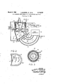
- FIGURE 1 is a schematic sectional view illustrating a high-intensity light source constructed in accordance with the present invention
- FIGURE 2 is a sectional view on line 2-2 of FIG- URE l;
- FIGURE 3 is a sectional view taken on line 3-3 of FIGURE 1.
- the high-intensity light source comprises wall means to define an annular vortex chamber 11 in which is disposed a generally conical back electrode 12 formed of tungsten or the like.
- the illustrated wall means 10 comprises a generally cup-shaped metal element 13 the bottom wall of which is relatively thick, such bottom wall having a nozzle opening 14 therein adapted to receive the tip or working portion of back electrode 12.
- the wall 16 of the opening 14 is concentric with electrode 12 but is spaced a substantial distance therefrom, the illustrated walls being generally parallel.
- Wall 16 is cooled through use of a chamber 17 formed in the bottom portion of element 13, such chamber containing water or other coolant which is passed therethrough by suitable conduit means 18.
- the wall means 10 also comprises a sleeve 29 formed of a suitable insulating material and inserted into the upper portion of the cup-shaped element 13.
- the upper portion of the sleeve is suitably formed, as by counterboring, to receive the downwardly-extending rim of a second cup-shaped metal element 21, the latter forming the upper wall of vortex chamber 11
- a flange 22 at the base of back electrode 12 is suitably secured to the center portion of the second cup-shaped element 21.
- a second coolant chamber 23 is formed See within the back electrode, which is hollow except at the tip, so that cooling water may be circulated therethrough by means of suitable conduits 24.
- the flange 22 on the back electrode has a cylindrical peripheral wall which is coaxial with the axis of the back electrode and is spaced radially-inwardly from the interior side wall of the second cup-shaped element 2-1.
- gas is introduced tangentially into the resulting annular space 26 for annular fiow therearound and thence for annular flow through the vortex chamber 11 and the communicating nozzle opening 14.
- the conduit 27 through which the gas is introduced into the annular space 26 forms part of a gas-recirculation system to be described subsequently.
- the apparatus further comprises a front electrode 28 (formed or" copper or the like) having a rear surface 29 which lies in a plane oblique to and intersecting the plane of the front or bottom surface 31 of cup-shaped element 13.
- the surfaces 29 and 31 may lie at approximately a forty-five degree angle relative to each other.
- the front electrode 28 is illustrated as being relatively thin, having an opening 32 therein the wall of which is suitably cooled. Such cooling is effected by use; of a cooling chamber 33 through which water is circulated by means of conduits 34.
- the opening 32 is not coaxial with the nozzle opening 14, being instead substantially offset therefrom and having an axis oblique to that of opening 14. It follows that the electric are 36 which is struck between the tip of back electrode 12 and the wall of opening 32 must turn a corner, or assume a curved shape, when in the arc chamber 38 which is defined between the obliquely-oriented surfaces 29 and 31. These relationships result in a highly efficient device wherein light generated by the arc is transmitted through a quartz window 37, such window extending between the surfaces 29 and 31 at the most widelyseparated regions thereof.
- a wall 39 of ceramic or other suitable insulator is extended from the peripheral portions of the window 37 around the peripheral portions of surfaces 29 and 31, as best indicated in FIGURE 2.
- a mirror 41 illustrated as comprising a paraboloid, is mounted in chamber 38 on the opposite side of thhe are 36 from window 37, that is to say between the window and those portions of surfaces 29 and 31 which are nearest to each other.
- the diameter of such opening is made relatively small (smaller than the effective cross-sectional area of opening 14 or conduit 27) in order that the gas pressure in chamber 38 may be made high.
- the hot gas or plasma emanating from opening 32 is cooled and recirculated back to the above-indicated conduit 27 through which it is injected tangentially into vortex chamber 11.
- the apparatus for effecting recirculation is illustrated to comprise a conduit 42 communicating with opening 32 and extending to a suitable heat exchanger which is schematically indicated at 43.
- the wall of conduit 42 may be cooled, as by means of a coolant chamber 44 which forms an extension of the cooling chamber 33.
- the water-cooled wall of conduit 42 and the heat exchanger 43 cooperate to cool the hot gas or plasma which discharges from the opening 32, so that such gas may be passed through a conventional variable-flow pump 46.
- the output from pump 46 communicates with the aboveindic'ated conduit 27 which extends to the annular space 26 in tangential relationship.
- a suitable current source is connected through leads 4-8 and 49 to the back and front 3 electrodes 12 and 28, respectively.
- the source 47 is preferably a DC. source adapted to deliver very high currents, such as hundreds or thousands of amperes, although it may be an alternating current source or a pulse source.
- back electrode 12 be the positive electrode, so that the arc footpoint at the tip of such electrode will be very hot and thus a primary source of light. Such footpoint is gas stabilized as will be described subsequently.
- Suitable means are provided to effect ionization of the gas in chamber 38 in order to initiate the electric arc 36 between the back and front electrodes.
- Such means may comprise, for example, a spark plug.
- the effective cross-sectional areas of conduit 27 and of opening 14 are each made substantially larger than the cross-sectional area of opening 32, so that the pressure within arc chamber 38 may be caused to be much higher than atmospheric.
- the pressure in the entire system may be caused to be substantially higher than atmospheric, for example many times atmospheric.
- the gas employed may be argon, xenon, krypton, or the like. The gas is continuously recirculated by means of the pump 46 at a desired rate, and at various desired gas pressures.
- the electric are 36 is initiated between the tip of back electrode 12 and the wall of opening 32 in front electrode 28, so that cur-rent flows from source 47 through lead 48, cup 21, back electrode 12, arc 36, and front electrode 28 back through lead 49 to the current source. Water is passed through the "arious conduit means 18, 24 and 34 to prevent overheating of the various elements.
- the vorticallyfiowing gas operates to effect gas stabilization of the are 36 at the portion thereof adjacent the tip of the back electrode.
- the upstream footpoint of the are 36 is thus centered at the electrode tip and is also constricted to a smaller crosssectional area than it would normally occupy in space.
- the upstream footpoint of the arc is extremely hot.
- the downstream footpoint of the arc is also relatively hot and (together with the adjacent gas) emits much light.
- the light emitted from the regions adjacent both of the footpoints, and also the light from the mid-portion of the are (which mid-portion is long due to the curved path followed by the arc in traveling from the upstream electrode to the opening 32), is transmitted through the quartz window 37 and employed as a black-body radiator, as a search light, runway light, etc. It is emphasized that if the surfaces 31 and 29 were not oblique to each other, the emission from the arc in the vicinity of the footpoints thereof would not pass through the window 37.
- the described highly efficient transmission of light through window 37 is caused to be even more efiicient because of the presence of the parabolic mirror 41, such mirror focusing light from the arc and transmitting the same through the window 37.
- the focal point of the mirror 41 is preferably disposed along the path of are 36.
- the gas pressure, the composition of the gas, etc. may be varied in order to change the spectroemission.
- a high-intensity light source comprising means to define first and second chambers separated by a wall, said wall having an opening therein effecting direct communication between said chambers, gas-inlet means to introduce gas in said first chamber, gas-outlet means to discharge gas from said second chamber, window means provided in the wall of said second chamber to transmit light from said second chamber, and means to maintain a high-current electric arc in said second chamber and extending at least from the vicinity of said opening to the vicinity of said gas-outlet means, said gas-outlet means being oifset from said opening to cause said arc to bend away from the axis of said opening and transmit light efficiently through said window means.
- a high-intensity light source which comprises an elongated back electrode having a relatively small-diameter tip adapted to form one terminus of an electric arc, wall means to define a nozzle opening around said tip and to define an arc chamber opposite said tip and communicating with said nozzle opening, said tip being set back from said are chamber whereby light generated at said tip and traveling perpendicular to the axis of said back electrode will be blocked by the portion of said wall means defining said nozzle opening, an outlet opening provided in said wall means generally opposite said tip but offset a substantial distance from the axis of said back electrode, a light-transmissive window provided in said wall means in spaced relationship from said outlet opening and disposed to transmit light from the portion of said are at said tip, means to maintain an electric arc in said are chamber between said tip and said outlet opening whereby the portion of said are adjacent said outlet opening is offset from the axis of said back electrode, and means to pass gas through said nozzle opening in a manner stabilizing the portion of said arc adjacent said tip.
- said wall means include two opposed walls lying generally in two intersecting planes which are oblique to eachother, one of said walls containing said nozzle opening.
- the invention is claimed in claim 5, in which means are provided to recirculate gas from said outlet opening to said nozzle opening, said means being adapted to maintain a high gas pressure in said are chamber and to vary both said pressure and the rate of gas recirculation.
- a high intensity light source which comprises wall means to define an arc chamber, at least a portion of said wall means being transparent and comprising a Window through which light may be discharged from said chamber, means to provide within said chamber a highly reflective mirror which is shaped and disposed to reflect light from a predetermined region of said chamber to and through said window, said mirror being directly exposed to said predetermined region and to the gas within said chamber whereby light from said predetermined region may pass from said predetermined region to said mirror and thence to said window without passing through any substance other than the gas within said chamber, electrode means disposed to maintain within said chamber a high-current electric arc at least a portion of which is located at said predetermined region, means to supply a large electric current to said electrode means to maintain said are therebetween, and means to maintain in said chamber a continuously-circulating gas under a pressure many times atmospheric, said last-named means including inlet means to introduce gas con inuously into said chamber, and outlet means to discharge said gas continuously from said chamber, said inlet means and outlet means being so located that at least a
- a high intensity light source which comprises wall means to define an arc chamber, at least a portion of said wall means being transparent and comprising a window through which light may be discharged from said chamber, means to provide within said chamber a highly reflective mirror which is shaped and disposed to reflect light from a predetermined region of said chamher to and through said window, said mirror being shaped as a surface of revolution about a predetermined 6 axis which extends through said predetermined region, electrode means disposed to maintain Within said chamber a continuous high-current electric are at least a portion of which is located at said region, means to supply an electric current to said electrode means to,
- said electric current having a magnitude at least on the order of hundreds of amperes, and means to maintain in said chamber a continuously-circulating inert gas under a pressure many times atmospheric, said last-named means including inlet means to introduce gas continuously into said chamber, outlet means to discharge said gas continuously from said chamber, and means including cooling means to recirculate said gas from said outlet means to said inlet means, said inlet means and outlet means being so located that at least a portion of said are is stabilized by said gas.
- said electrode means comprises a first electrode having a relatively pointed arcing end portion disposed adjacent said predetermined region of said chamber, and a second electrode having an arcing portion also disposed adjacent said pretedmined region of said chamber; and in which said outlet means is located adjacent at least one of said arcing portions of said electrodes.
Landscapes
- Physics & Mathematics (AREA)
- Engineering & Computer Science (AREA)
- Plasma & Fusion (AREA)
- Spectroscopy & Molecular Physics (AREA)
- Plasma Technology (AREA)
Description
United States Patent 3,172,000 GAS DISHARGE LIGHT SOURCE W A RECIRCULATING GAS SUPPLY Joseph Roseiier, Jr., and Delbert G. Van Ornurn, Newport Beach, Calif-., assignors, by mesne assignments, to Giannini Scientific Corporation, Long Island, N.Y., a corporation of Delaware Filed Aug. 31, 1961, Ser. No. 135,372 16 Claims. (Cl. 313-12) This invention relates to a high-intensity light, and more particularly to a high-intensity light having relatively efficient light-radiating characteristics.
An object of the present invention is to provide a source of high-intensity light for various purposes including use in the graphic-arts industry and in space communications, as well as for a search light, runway light, blackbody raditor, etc.
A further object is to providea highly efficient light source characterized by the presence of a mirror in the high-pressure arc chamber.
A further object is to provide a light source which simulates the emission of light from a blackbody radiator, and which permits the spectroemission to be varied as desired.
A further object is to provide a high-intensity light source incorporating a stable arc column all portions of which are viewed directly and contribute to the light emission.
A further object is to provide a light source incorporating a gas-stabilized are which is curved in order that substantially all portions of the arc column may be effectively employed to radiate light.
These and other objects and advantages of the invention will be more fully set forth in the following specification and claims, considered in connection with the attached drawing to which they relate.
In the drawing:
FIGURE 1 is a schematic sectional view illustrating a high-intensity light source constructed in accordance with the present invention;
FIGURE 2 is a sectional view on line 2-2 of FIG- URE l; and
FIGURE 3 is a sectional view taken on line 3-3 of FIGURE 1.
Referring to FIGURE 1, the high-intensity light source comprises wall means to define an annular vortex chamber 11 in which is disposed a generally conical back electrode 12 formed of tungsten or the like. The illustrated wall means 10 comprises a generally cup-shaped metal element 13 the bottom wall of which is relatively thick, such bottom wall having a nozzle opening 14 therein adapted to receive the tip or working portion of back electrode 12.
The wall 16 of the opening 14 is concentric with electrode 12 but is spaced a substantial distance therefrom, the illustrated walls being generally parallel. Wall 16 is cooled through use of a chamber 17 formed in the bottom portion of element 13, such chamber containing water or other coolant which is passed therethrough by suitable conduit means 18.
The wall means 10 also comprises a sleeve 29 formed of a suitable insulating material and inserted into the upper portion of the cup-shaped element 13. The upper portion of the sleeve is suitably formed, as by counterboring, to receive the downwardly-extending rim of a second cup-shaped metal element 21, the latter forming the upper wall of vortex chamber 11 A flange 22 at the base of back electrode 12 is suitably secured to the center portion of the second cup-shaped element 21. Thus, a second coolant chamber 23 is formed See within the back electrode, which is hollow except at the tip, so that cooling water may be circulated therethrough by means of suitable conduits 24.
The flange 22 on the back electrode has a cylindrical peripheral wall which is coaxial with the axis of the back electrode and is spaced radially-inwardly from the interior side wall of the second cup-shaped element 2-1. As best illustrated in FIGURE 3, gas is introduced tangentially into the resulting annular space 26 for annular fiow therearound and thence for annular flow through the vortex chamber 11 and the communicating nozzle opening 14. The conduit 27 through which the gas is introduced into the annular space 26 forms part of a gas-recirculation system to be described subsequently.
The apparatus further comprises a front electrode 28 (formed or" copper or the like) having a rear surface 29 which lies in a plane oblique to and intersecting the plane of the front or bottom surface 31 of cup-shaped element 13. For example, the surfaces 29 and 31 may lie at approximately a forty-five degree angle relative to each other. The front electrode 28 is illustrated as being relatively thin, having an opening 32 therein the wall of which is suitably cooled. Such cooling is effected by use; of a cooling chamber 33 through which water is circulated by means of conduits 34.
It is an important feature of the invention that the opening 32 is not coaxial with the nozzle opening 14, being instead substantially offset therefrom and having an axis oblique to that of opening 14. It follows that the electric are 36 which is struck between the tip of back electrode 12 and the wall of opening 32 must turn a corner, or assume a curved shape, when in the arc chamber 38 which is defined between the obliquely-oriented surfaces 29 and 31. These relationships result in a highly efficient device wherein light generated by the arc is transmitted through a quartz window 37, such window extending between the surfaces 29 and 31 at the most widelyseparated regions thereof.
In order to define the chamber 38 between the surfaces 29 and 31, a wall 39 of ceramic or other suitable insulator is extended from the peripheral portions of the window 37 around the peripheral portions of surfaces 29 and 31, as best indicated in FIGURE 2. A mirror 41, illustrated as comprising a paraboloid, is mounted in chamber 38 on the opposite side of thhe are 36 from window 37, that is to say between the window and those portions of surfaces 29 and 31 which are nearest to each other.
In apparatus where the opening 32 communicates with the ambient atmosphere, the diameter of such opening is made relatively small (smaller than the effective cross-sectional area of opening 14 or conduit 27) in order that the gas pressure in chamber 38 may be made high. In the illustrated apparatus, the hot gas or plasma emanating from opening 32 is cooled and recirculated back to the above-indicated conduit 27 through which it is injected tangentially into vortex chamber 11.
The apparatus for effecting recirculation is illustrated to comprise a conduit 42 communicating with opening 32 and extending to a suitable heat exchanger which is schematically indicated at 43. The wall of conduit 42 may be cooled, as by means of a coolant chamber 44 which forms an extension of the cooling chamber 33. The water-cooled wall of conduit 42 and the heat exchanger 43 cooperate to cool the hot gas or plasma which discharges from the opening 32, so that such gas may be passed through a conventional variable-flow pump 46. The output from pump 46 communicates with the aboveindic'ated conduit 27 which extends to the annular space 26 in tangential relationship.
A suitable current source, schematically indicated at 47, is connected through leads 4-8 and 49 to the back and front 3 electrodes 12 and 28, respectively. The source 47 is preferably a DC. source adapted to deliver very high currents, such as hundreds or thousands of amperes, although it may be an alternating current source or a pulse source. It is preferred that back electrode 12 be the positive electrode, so that the arc footpoint at the tip of such electrode will be very hot and thus a primary source of light. Such footpoint is gas stabilized as will be described subsequently.
Suitable means, not shown, are provided to effect ionization of the gas in chamber 38 in order to initiate the electric arc 36 between the back and front electrodes. Such means may comprise, for example, a spark plug.
Method of operation In apparatus where there is no means to recirculate the gas, and as previously stated, the effective cross-sectional areas of conduit 27 and of opening 14 are each made substantially larger than the cross-sectional area of opening 32, so that the pressure within arc chamber 38 may be caused to be much higher than atmospheric. In the illustrated system, wherein means to recirculate the gas are provided, the pressure in the entire system may be caused to be substantially higher than atmospheric, for example many times atmospheric. The gas employed may be argon, xenon, krypton, or the like. The gas is continuously recirculated by means of the pump 46 at a desired rate, and at various desired gas pressures.
The electric are 36 is initiated between the tip of back electrode 12 and the wall of opening 32 in front electrode 28, so that cur-rent flows from source 47 through lead 48, cup 21, back electrode 12, arc 36, and front electrode 28 back through lead 49 to the current source. Water is passed through the "arious conduit means 18, 24 and 34 to prevent overheating of the various elements.
The gas which is pumped through conduit 27 tangentially into the annular space 26 and vortex chamber 11 flows vortically or helically at a rapid rate. The vorticallyfiowing gas operates to effect gas stabilization of the are 36 at the portion thereof adjacent the tip of the back electrode. The upstream footpoint of the are 36 is thus centered at the electrode tip and is also constricted to a smaller crosssectional area than it would normally occupy in space.
Particularly when the back electrode 12 is caused to have a positive polarity, the upstream footpoint of the arc is extremely hot. Such upstream footpoint, and the gas adjacent thereto, therefore radiate large amounts of light. The downstream footpoint of the arc is also relatively hot and (together with the adjacent gas) emits much light. The light emitted from the regions adjacent both of the footpoints, and also the light from the mid-portion of the are (which mid-portion is long due to the curved path followed by the arc in traveling from the upstream electrode to the opening 32), is transmitted through the quartz window 37 and employed as a black-body radiator, as a search light, runway light, etc. It is emphasized that if the surfaces 31 and 29 were not oblique to each other, the emission from the arc in the vicinity of the footpoints thereof would not pass through the window 37.
The described highly efficient transmission of light through window 37 is caused to be even more efiicient because of the presence of the parabolic mirror 41, such mirror focusing light from the arc and transmitting the same through the window 37. The focal point of the mirror 41 is preferably disposed along the path of are 36.
Where the light source is employed for spectroscopic purposes, the gas pressure, the composition of the gas, etc., may be varied in order to change the spectroemission.
Various embodiments of the present invention, in addition to what has been illustrated and described in detail, may be employed without departing from the scope of the accompanying claims.
We claim:
1. A high-intensity light source, comprising means to define first and second chambers separated by a wall, said wall having an opening therein effecting direct communication between said chambers, gas-inlet means to introduce gas in said first chamber, gas-outlet means to discharge gas from said second chamber, window means provided in the wall of said second chamber to transmit light from said second chamber, and means to maintain a high-current electric arc in said second chamber and extending at least from the vicinity of said opening to the vicinity of said gas-outlet means, said gas-outlet means being oifset from said opening to cause said arc to bend away from the axis of said opening and transmit light efficiently through said window means.
2. The invention as claimed in claim 1, in which said gas-inlet means and said chamber-defining means are adapted to effect vortical flow of gas in said first chamber and in said opening.
3. The invention as claimed in claim 1, in which means are rovided to recirculate said gas from said gas-outlet means to said gas-inlet means and to cool said gas during such recirculation.
4. The invention as claimed in claim 1, in which said gas-outlet means has a cross-sectional area substantially smaller than that of said gas-inlet means and of said opening, whereby the pressure of said gas in said second chamber may be increased to a high value.
5. A high-intensity light source, which comprises an elongated back electrode having a relatively small-diameter tip adapted to form one terminus of an electric arc, wall means to define a nozzle opening around said tip and to define an arc chamber opposite said tip and communicating with said nozzle opening, said tip being set back from said are chamber whereby light generated at said tip and traveling perpendicular to the axis of said back electrode will be blocked by the portion of said wall means defining said nozzle opening, an outlet opening provided in said wall means generally opposite said tip but offset a substantial distance from the axis of said back electrode, a light-transmissive window provided in said wall means in spaced relationship from said outlet opening and disposed to transmit light from the portion of said are at said tip, means to maintain an electric arc in said are chamber between said tip and said outlet opening whereby the portion of said are adjacent said outlet opening is offset from the axis of said back electrode, and means to pass gas through said nozzle opening in a manner stabilizing the portion of said arc adjacent said tip.
6. The invention as claimed in claim 5, in which additional wall means are provided to define an annular gas vortex chamber around said back electrode coaxially of said nozzle opening, and in which said last-named means is disposed to introduce gas tangentially into said vortex chamber for vortical flow therein and in said nozzle opening.
7. The invention as claim in claim 6, in which said tip is generally conical, and in which the wall of said nozzle opening is a surface of revolution about the axis of said tip, said surface being spaced radially outwardly from said tip and converging from said vortex chamber to said arc. chamber.
8. The invention as claimed in claim 5, in which said means to maintain said are included a DC. source having the positive terminal thereof connected to said back. electrode.
9. The invention as claimed in claim 5, in which said wall means include two opposed walls lying generally in two intersecting planes which are oblique to eachother, one of said walls containing said nozzle opening.
and the other of said walls containing said outlet opening,
in which said window extends between relatively remote.
5 side of said are from said window, said mirror being a paraboloid and directed toward said window.
11. The invention is claimed in claim 5, in which means are provided to recirculate gas from said outlet opening to said nozzle opening, said means being adapted to maintain a high gas pressure in said are chamber and to vary both said pressure and the rate of gas recirculation.
12. A high intensity light source, which comprises wall means to define an arc chamber, at least a portion of said wall means being transparent and comprising a Window through which light may be discharged from said chamber, means to provide within said chamber a highly reflective mirror which is shaped and disposed to reflect light from a predetermined region of said chamber to and through said window, said mirror being directly exposed to said predetermined region and to the gas within said chamber whereby light from said predetermined region may pass from said predetermined region to said mirror and thence to said window without passing through any substance other than the gas within said chamber, electrode means disposed to maintain within said chamber a high-current electric arc at least a portion of which is located at said predetermined region, means to supply a large electric current to said electrode means to maintain said are therebetween, and means to maintain in said chamber a continuously-circulating gas under a pressure many times atmospheric, said last-named means including inlet means to introduce gas con inuously into said chamber, and outlet means to discharge said gas continuously from said chamber, said inlet means and outlet means being so located that at least a portion of said are is stabilized by said gas.
13. A high intensity light source, which comprises wall means to define an arc chamber, at least a portion of said wall means being transparent and comprising a window through which light may be discharged from said chamber, means to provide within said chamber a highly reflective mirror which is shaped and disposed to reflect light from a predetermined region of said chamher to and through said window, said mirror being shaped as a surface of revolution about a predetermined 6 axis which extends through said predetermined region, electrode means disposed to maintain Within said chamber a continuous high-current electric are at least a portion of which is located at said region, means to supply an electric current to said electrode means to,
maintain said are therebetween, said electric current having a magnitude at least on the order of hundreds of amperes, and means to maintain in said chamber a continuously-circulating inert gas under a pressure many times atmospheric, said last-named means including inlet means to introduce gas continuously into said chamber, outlet means to discharge said gas continuously from said chamber, and means including cooling means to recirculate said gas from said outlet means to said inlet means, said inlet means and outlet means being so located that at least a portion of said are is stabilized by said gas.
14. The invention as claimed in claim 13, in which said gas is selected from a group consisting of argon, xenon, and krypton.
15. The invention as claimed in claim 13, in which said mirror is directly exposed to said predetermined region and to the gas within said chamber whereby light from said predetermined region may pass from said predetermined region to said mirror and thence to said window without passing through any substance other than the gas within said chamber.
16. The invention as claimed in claim 13, in which said electrode means comprises a first electrode having a relatively pointed arcing end portion disposed adjacent said predetermined region of said chamber, and a second electrode having an arcing portion also disposed adjacent said pretedmined region of said chamber; and in which said outlet means is located adjacent at least one of said arcing portions of said electrodes.
References Cited in the file of this patent UNITED STATES PATENTS 2,063,929 Hutaif et al Dec. 15, 1936 2,190,657 Germer Feb. 20, 1940 2,929,952 Giannini et al Mar. 22, 1960 3,064,153 Gage Nov. 13, 1962
Claims (1)
13. A HIGH INTENSITY LIGHT SOURCE, WHICH COMPRISES WALL MEANS TO DEFINE AN ARC CHAMBER, AT LEAST A PORTION OF SAID WALL MEANS BEING TRANSPARENT AND COMPRISING A WINDOW THROUGH WHICH LIGHT MAY BE DISCHARGED FROM SAID CHAMBER, MEANS TO PROVIDE WITHIN SAID CHAMBER A HIGHLY REFLECTIVE MIRROR WHICH IS SHAPED AND DISPOSED TO REFLECT LIGHT FROM PREDETERMINED REGION OF SAID CHAMBER TO AND THROUGH SAID WINDOW, SAID MORROR BEING SHAPED AS A SURFACE OF REVOLUTION ABOUT PREDETERMINED AXIS WHICH EXTENDS THROUGH SAID PREDETERMINED REGION, ELECTRODE MEANS DISPOSED TO MAINTAIN WITHIN SAID CHAMBER A CONTINUOUS HIGH-CURRENT ELECTRIC ARC AT LEAST A PORTION OF WHICH IS LOCATED AT SAID REGION, MEANS TO SUPPLY AN ELECTRIC CURRENT TO SAID ELECTRODE MEANS TO MAINTAIN SAID ARC THEREBETWEEN, SAID ELECTRIC CURRENT HAVING A MAGNITUDE AT LEAST ON THE ORDER OF HUNDREDS OF AMPERES, AND MEANS TO MAINTAIN IN SAID CHAMBER A CONTINUOUSLY-CIRCULATING INSERT GAS UNDER A PRESSURE MANY TIMES ATMOSPHERIC, SAID LAST-NAMED MEANS INCLUDING INLET MEANS INTRODUCE GAS CONTINUOUSLY INTO SAID CHAMBER, OUTLET MEANS TO DISCHARGE SAID GAS CONTINUOUSLY FROM SAID CHAMBER, AND MEANS INCLUDING COOLING MEANS TO RECIRCULATE SAID GAS FROM SAID OUTLET MEANS TO SAID INLET MEANS, SAID INLET MEANS AND OUTLET MEANS BEING SO LOCATED THAT AT LEAST A PORTION OF SAID ARC IS STABILIZED BY SAID GAS.
Priority Applications (1)
| Application Number | Priority Date | Filing Date | Title |
|---|---|---|---|
| US135372A US3172000A (en) | 1961-08-31 | 1961-08-31 | Gas discharge light source with a recirculating gas supply |
Applications Claiming Priority (1)
| Application Number | Priority Date | Filing Date | Title |
|---|---|---|---|
| US135372A US3172000A (en) | 1961-08-31 | 1961-08-31 | Gas discharge light source with a recirculating gas supply |
Publications (1)
| Publication Number | Publication Date |
|---|---|
| US3172000A true US3172000A (en) | 1965-03-02 |
Family
ID=22467806
Family Applications (1)
| Application Number | Title | Priority Date | Filing Date |
|---|---|---|---|
| US135372A Expired - Lifetime US3172000A (en) | 1961-08-31 | 1961-08-31 | Gas discharge light source with a recirculating gas supply |
Country Status (1)
| Country | Link |
|---|---|
| US (1) | US3172000A (en) |
Cited By (9)
| Publication number | Priority date | Publication date | Assignee | Title |
|---|---|---|---|---|
| US3222569A (en) * | 1961-05-22 | 1965-12-07 | Giannini Scient Corp | Apparatus and method for generating high-intensity light |
| US3292028A (en) * | 1962-06-20 | 1966-12-13 | Giannini Scient Corp | Gas vortex-stabilized light source |
| US3327113A (en) * | 1962-06-27 | 1967-06-20 | Frank W Brown | Solar radiation simulator including carbon electrodes in an oxygen and helium environment |
| US3405314A (en) * | 1963-11-18 | 1968-10-08 | Giannini Scient Corp | High-pressure light source having inclined tangential gas supply passages |
| US3418524A (en) * | 1965-11-29 | 1968-12-24 | Giannini Scient Corp | Apparatus and method for generating high-intensity light |
| US3512030A (en) * | 1967-06-16 | 1970-05-12 | Vitro Corp Of America | High intensity source of selected radiation |
| FR2159271A1 (en) * | 1971-11-12 | 1973-06-22 | Metco Inc | |
| US4368538A (en) * | 1980-04-11 | 1983-01-11 | International Business Machines Corporation | Spot focus flash X-ray source |
| US4496873A (en) * | 1981-06-05 | 1985-01-29 | Commissariat A L'energie Atomique | Flash tube having coax cable connector |
Citations (4)
| Publication number | Priority date | Publication date | Assignee | Title |
|---|---|---|---|---|
| US2063929A (en) * | 1935-06-28 | 1936-12-15 | Jr George H Hutaff | Mirrored electric light tubing |
| US2190657A (en) * | 1936-12-01 | 1940-02-20 | Germer Edmund | Discharge device |
| US2929952A (en) * | 1958-10-20 | 1960-03-22 | Plasmadyne Corp | Self-circulating plasma device |
| US3064153A (en) * | 1958-09-08 | 1962-11-13 | Union Carbide Corp | High intensity light source |
-
1961
- 1961-08-31 US US135372A patent/US3172000A/en not_active Expired - Lifetime
Patent Citations (4)
| Publication number | Priority date | Publication date | Assignee | Title |
|---|---|---|---|---|
| US2063929A (en) * | 1935-06-28 | 1936-12-15 | Jr George H Hutaff | Mirrored electric light tubing |
| US2190657A (en) * | 1936-12-01 | 1940-02-20 | Germer Edmund | Discharge device |
| US3064153A (en) * | 1958-09-08 | 1962-11-13 | Union Carbide Corp | High intensity light source |
| US2929952A (en) * | 1958-10-20 | 1960-03-22 | Plasmadyne Corp | Self-circulating plasma device |
Cited By (9)
| Publication number | Priority date | Publication date | Assignee | Title |
|---|---|---|---|---|
| US3222569A (en) * | 1961-05-22 | 1965-12-07 | Giannini Scient Corp | Apparatus and method for generating high-intensity light |
| US3292028A (en) * | 1962-06-20 | 1966-12-13 | Giannini Scient Corp | Gas vortex-stabilized light source |
| US3327113A (en) * | 1962-06-27 | 1967-06-20 | Frank W Brown | Solar radiation simulator including carbon electrodes in an oxygen and helium environment |
| US3405314A (en) * | 1963-11-18 | 1968-10-08 | Giannini Scient Corp | High-pressure light source having inclined tangential gas supply passages |
| US3418524A (en) * | 1965-11-29 | 1968-12-24 | Giannini Scient Corp | Apparatus and method for generating high-intensity light |
| US3512030A (en) * | 1967-06-16 | 1970-05-12 | Vitro Corp Of America | High intensity source of selected radiation |
| FR2159271A1 (en) * | 1971-11-12 | 1973-06-22 | Metco Inc | |
| US4368538A (en) * | 1980-04-11 | 1983-01-11 | International Business Machines Corporation | Spot focus flash X-ray source |
| US4496873A (en) * | 1981-06-05 | 1985-01-29 | Commissariat A L'energie Atomique | Flash tube having coax cable connector |
Similar Documents
| Publication | Publication Date | Title |
|---|---|---|
| Cobine et al. | The electronic torch and related high frequency phenomena | |
| US3324334A (en) | Induction plasma torch with means for recirculating the plasma | |
| US3292028A (en) | Gas vortex-stabilized light source | |
| US4633492A (en) | Plasma pinch X-ray method | |
| US3064153A (en) | High intensity light source | |
| US3227923A (en) | Electrodeless vapor discharge lamp with auxiliary radiation triggering means | |
| US3172000A (en) | Gas discharge light source with a recirculating gas supply | |
| US2837654A (en) | Process and apparatus for carrying out reactions by the action of electrical glow discharges | |
| US3360682A (en) | Apparatus and method for generating high-enthalpy plasma under high-pressure conditions | |
| US4027185A (en) | High intensity radiation source | |
| US2929952A (en) | Self-circulating plasma device | |
| US3686528A (en) | Jet pinched plasma arc lamp and method of forming plasma arc | |
| US3201560A (en) | Electric-arc heater | |
| US3364387A (en) | Radiation torch having an electrode for supplying and exhausting gas | |
| US3026435A (en) | Ultraviolet lamp | |
| US3405305A (en) | Vortex-stabilized radiation source with a hollowed-out electrode | |
| US3597650A (en) | Arc radiation sources | |
| US4074208A (en) | Stabilized repetitively pulsed flashlamps | |
| US4178078A (en) | Aerodynamic window | |
| US3378713A (en) | High-intensity radiation source comprising rotating arc | |
| US3290552A (en) | Apparatus for generating high-intensity light with high temperature particulate material | |
| US3233147A (en) | Apparatus and method for generating high-intensity light and a high temperature and mach number plasma stream | |
| US3551737A (en) | Gas vortex-stabilized radiation source and method,and additive-introduction means therefor | |
| US3480829A (en) | Electric arc light source and method | |
| US3280360A (en) | High intensity radiation source |