US3137125A - Solar motor - Google Patents
Solar motor Download PDFInfo
- Publication number
- US3137125A US3137125A US175846A US17584662A US3137125A US 3137125 A US3137125 A US 3137125A US 175846 A US175846 A US 175846A US 17584662 A US17584662 A US 17584662A US 3137125 A US3137125 A US 3137125A
- Authority
- US
- United States
- Prior art keywords
- vanes
- heat
- layer
- rotor
- cylinder
- Prior art date
- Legal status (The legal status is an assumption and is not a legal conclusion. Google has not performed a legal analysis and makes no representation as to the accuracy of the status listed.)
- Expired - Lifetime
Links
- 239000004020 conductor Substances 0.000 claims description 9
- 229910052782 aluminium Inorganic materials 0.000 description 4
- XAGFODPZIPBFFR-UHFFFAOYSA-N aluminium Chemical compound [Al] XAGFODPZIPBFFR-UHFFFAOYSA-N 0.000 description 4
- 229920003023 plastic Polymers 0.000 description 4
- XLYOFNOQVPJJNP-UHFFFAOYSA-N water Substances O XLYOFNOQVPJJNP-UHFFFAOYSA-N 0.000 description 4
- OKTJSMMVPCPJKN-UHFFFAOYSA-N Carbon Chemical compound [C] OKTJSMMVPCPJKN-UHFFFAOYSA-N 0.000 description 3
- 239000000463 material Substances 0.000 description 3
- 239000004033 plastic Substances 0.000 description 3
- 230000002745 absorbent Effects 0.000 description 2
- 239000002250 absorbent Substances 0.000 description 2
- 238000010276 construction Methods 0.000 description 2
- 230000000694 effects Effects 0.000 description 2
- 239000004922 lacquer Substances 0.000 description 2
- 239000006233 lamp black Substances 0.000 description 2
- 239000000843 powder Substances 0.000 description 2
- 239000004065 semiconductor Substances 0.000 description 2
- 239000002023 wood Substances 0.000 description 2
- ZOXJGFHDIHLPTG-UHFFFAOYSA-N Boron Chemical compound [B] ZOXJGFHDIHLPTG-UHFFFAOYSA-N 0.000 description 1
- XUIMIQQOPSSXEZ-UHFFFAOYSA-N Silicon Chemical compound [Si] XUIMIQQOPSSXEZ-UHFFFAOYSA-N 0.000 description 1
- 229910000831 Steel Inorganic materials 0.000 description 1
- 238000007664 blowing Methods 0.000 description 1
- 229910052796 boron Inorganic materials 0.000 description 1
- 229910052799 carbon Inorganic materials 0.000 description 1
- 239000011248 coating agent Substances 0.000 description 1
- 238000000576 coating method Methods 0.000 description 1
- 238000001816 cooling Methods 0.000 description 1
- 210000003298 dental enamel Anatomy 0.000 description 1
- 229910003460 diamond Inorganic materials 0.000 description 1
- 239000010432 diamond Substances 0.000 description 1
- 239000011521 glass Substances 0.000 description 1
- 239000004519 grease Substances 0.000 description 1
- 238000009434 installation Methods 0.000 description 1
- 239000007788 liquid Substances 0.000 description 1
- 229910052751 metal Inorganic materials 0.000 description 1
- 239000002184 metal Substances 0.000 description 1
- 239000007769 metal material Substances 0.000 description 1
- 238000005086 pumping Methods 0.000 description 1
- 239000002990 reinforced plastic Substances 0.000 description 1
- 230000003014 reinforcing effect Effects 0.000 description 1
- 230000000630 rising effect Effects 0.000 description 1
- 229910052710 silicon Inorganic materials 0.000 description 1
- 239000010703 silicon Substances 0.000 description 1
- 229910052709 silver Inorganic materials 0.000 description 1
- 239000004332 silver Substances 0.000 description 1
- 239000007921 spray Substances 0.000 description 1
- 239000010959 steel Substances 0.000 description 1
- 239000012780 transparent material Substances 0.000 description 1
- 239000002966 varnish Substances 0.000 description 1
Images

Classifications
-
- F—MECHANICAL ENGINEERING; LIGHTING; HEATING; WEAPONS; BLASTING
- F03—MACHINES OR ENGINES FOR LIQUIDS; WIND, SPRING, OR WEIGHT MOTORS; PRODUCING MECHANICAL POWER OR A REACTIVE PROPULSIVE THRUST, NOT OTHERWISE PROVIDED FOR
- F03G—SPRING, WEIGHT, INERTIA OR LIKE MOTORS; MECHANICAL-POWER PRODUCING DEVICES OR MECHANISMS, NOT OTHERWISE PROVIDED FOR OR USING ENERGY SOURCES NOT OTHERWISE PROVIDED FOR
- F03G6/00—Devices for producing mechanical power from solar energy
- F03G6/02—Devices for producing mechanical power from solar energy using a single state working fluid
- F03G6/04—Devices for producing mechanical power from solar energy using a single state working fluid gaseous
- F03G6/045—Devices for producing mechanical power from solar energy using a single state working fluid gaseous by producing an updraft of heated gas or a downdraft of cooled gas, e.g. air driving an engine
-
- Y—GENERAL TAGGING OF NEW TECHNOLOGICAL DEVELOPMENTS; GENERAL TAGGING OF CROSS-SECTIONAL TECHNOLOGIES SPANNING OVER SEVERAL SECTIONS OF THE IPC; TECHNICAL SUBJECTS COVERED BY FORMER USPC CROSS-REFERENCE ART COLLECTIONS [XRACs] AND DIGESTS
- Y02—TECHNOLOGIES OR APPLICATIONS FOR MITIGATION OR ADAPTATION AGAINST CLIMATE CHANGE
- Y02E—REDUCTION OF GREENHOUSE GAS [GHG] EMISSIONS, RELATED TO ENERGY GENERATION, TRANSMISSION OR DISTRIBUTION
- Y02E10/00—Energy generation through renewable energy sources
- Y02E10/40—Solar thermal energy, e.g. solar towers
- Y02E10/46—Conversion of thermal power into mechanical power, e.g. Rankine, Stirling or solar thermal engines
-
- Y—GENERAL TAGGING OF NEW TECHNOLOGICAL DEVELOPMENTS; GENERAL TAGGING OF CROSS-SECTIONAL TECHNOLOGIES SPANNING OVER SEVERAL SECTIONS OF THE IPC; TECHNICAL SUBJECTS COVERED BY FORMER USPC CROSS-REFERENCE ART COLLECTIONS [XRACs] AND DIGESTS
- Y10—TECHNICAL SUBJECTS COVERED BY FORMER USPC
- Y10S—TECHNICAL SUBJECTS COVERED BY FORMER USPC CROSS-REFERENCE ART COLLECTIONS [XRACs] AND DIGESTS
- Y10S415/00—Rotary kinetic fluid motors or pumps
- Y10S415/909—Air stack or shaft having natural fluid current motor
Definitions
- the present invention contemplates a solar motor large enough and eiiicient enough to provide the necessary pow-l er to operate a water pump, for example. Such an installation'would be particularly useful in pumping water in remote desert areas having ample sunshine.
- An important object of the Ainvention is to provide a laminated rotor vane which will make maximum use of the sunlight it receives and convert it into useful energy with a high degree of eiciency.
- FIGURE 1 is a plan view of the preferred embodiment ofthe solar motor.
- FIGURE 2 is'a vertical section taken on the line 2-2 of FIGURE l with parts of the motor being shown in elevation.
- FIGURE 3 is an enlarged section of a portion of a rotor vane.
- FIGURE 4 is avertical section, part in elevation, of a modified form of the solar motor.
- the solar motor is provide with a stator, generally indicated by the numeral 10, and consisting of a circular base 11 of wood or reinforced plastic. Mounted on the base 11 is a centrally disposed vertical support 12 which is tted at its top end with a seat 14. This seat encloses a suitable bearing, not shown, which may be a diamond or glass, for example.
- an open-ended cylinder 16 preferably of clear transparent, plastic, which cylinder is securely aixed to the base 11.
- a number of equidistantly spaced inlet vanes 17 are mounted on the base, which vanes may be formed of very thin transparent plastic. The vertical vanes 17 are above the base 11 to permit air to enter between the vanes.
- the stator supports a rotor 20 consisting of inner and outer concentrically disposed cylinders 21 and 22 respectively. Both these cylinders are open-ended structures and a clear, transparent and very thin plastic is used in their construction.
- the lower edges of the cylinders 21 and 22 are connected by a number of circumferentially spaced sticks 24.
- the upper end of the inner cylinder 21 is bridged by four radial arms 25.
- a steel pivot pin 27 is secured to the underside of the arms at the centre of the inner cylinder and the tip of this pin is journalled in the bearing carried bythe seat 14.
- the rotor 20 is fitted with several vanes 29, the lower edges of which are secured to the sticks 24. These vanes extend upwardly from their supporting sticks at an angle ice of substantially 45 to a horizontal plane and the side edges of said vanes may be suitably secured to the peripheries of the cylinders 21 and 22. i
- vanes 29 are of laminate construction and are made up of three layers A, B and C.
- the bottom layer C is the thinnest commercially sold aluminum which is a good conductor of heat.
- Layer B is a semi-conductor of heat and is made up by mixing the following materials in the proportions noted:
- vanes 29 are constructed to form what might be referred to as an absorbent transformer since the vanes are designed to absorb the suns radiant energy and transform it into heat energy.
- the thickness of the vanes 29 is less than .015 of a millimeter but this has been found to provide sufficient structural strength. If the cost of the vanes is not a consideration andeven greater efficiency is desired layer C can be made of silver, layer B of silicon (treated with lamp black or the like to improve its heat absorbent qualities) and layer A can be formed of boron.
- the modified form of the solar motor shown in FIG. 4 has a stator consisting of a base 111, cylinder 161, vanes 171, and an outer cylinder 181 all of which are constructed substantially as before.
- a cone-shaped extension 35 is fitted to the top of the cylinder 181 which extension is intended to give a Venturi effect to the air owing upwardly through said cylinder.
- the cylinder 181 is fitted at each open end with reinforcing spokes 37 which are formed preferably of thin aluminum tubing.
- a roller bearing 38 is provided at the hub formed by the radial spokes at each end of the cylinder.
- stator 41 Journalled in the bearings 38 is the tubular aluminum shaft 40 of a modified stator 41.
- stator has an inner cylinder 211 only and the vanes 291 are helically wound around this cylinder and are suitably secured. thereto.
- the outer edges of the vanes are reinforced by thin wooden strips 43 and at suitable intervals said strips are supported by vertically spaced strips 44, also of thin wood.
- the strips 44 are horizontally and radially disposed and extend through the cylinder 211 for connection to the shaft 40.
- a crank 47 is fitted to the shaft 40 and said crank is connected by a rod 48 to the operating handle 49 of a water pump 50.
- the pump may be intended to draw water from a well and discharge it into a container 51.
- this mechanism is shown only as an example of the use to which the solar motor may be put and detailed description is deemed unnecessary.
- a fence 54 may be erected around the base of the motor on the side or sides of the prevailing winds to protect tbe thin it heats very quickly and being a semi-conductor of ⁇ heat also heats fairly evenly throughout.
- Layer AV which is a relatively poor conductor of heat will restrict heat ow in an upward direction and in doing so will achieve what might be referred to as a greenhouse effect.
- the heat in layer B will ow into layer C which is a good conductor of heat and since it has this property will readily heat the air immediately below the vanes.
- the cylinders 21 and 22V prevent the rising air from escaping to the side and the space between the cylinder 22 and the stator cylinder 18v provide for by-pass cooling.
- Vsaid vanes comprising a bottom, intermediate and top layer, said bottom layer being a good conductor of heat, said intermediate layer being a fair conductor of heat and said top layer being a poor conductor of heat whereby solar heat is amplified by the top layer for storage in the intermediate layer and subsequent transfer by the bottom layer to the air beneath the rotor vane.
Landscapes
- Engineering & Computer Science (AREA)
- Chemical & Material Sciences (AREA)
- Combustion & Propulsion (AREA)
- Life Sciences & Earth Sciences (AREA)
- Sustainable Development (AREA)
- Sustainable Energy (AREA)
- Mechanical Engineering (AREA)
- General Engineering & Computer Science (AREA)
- Wind Motors (AREA)
Description
June 16, 1.964 w. F. KYRYLUK 3,137,125
` SOLAR MOTOR June 16, 1964 w. F. KYRYLUK 3,137,125
SOLAR MOTOR Filed Feb. 26, 1962 `2 Sheets-Sheei'I 2 @0MM mw.
United States Patent O 3,137,125 SOLAR MOTOR William Frederick Kyryluk, Los Angeles, Calif. (362 W. 18th Ave., Vancouver 10, British Columbia, Canada) Filed Feb. 26, 1962, Ser. No. 175,846 4 Claims. `(Cl; 60-26) My invention relates to a motor which is adapted to receive radiant energy from the sun and convert it into useful mechanical energy.
An earlier device designed to transform solar energy into mechanical energy was the radiometer, an instrument used for measuring the intensity of radiant energy, and for similar purposes. Because of its limitations as to size and the fact that a partial vacuum is required no means could be found for modifying the radiometer so that it could do useful work.
The present invention contemplates a solar motor large enough and eiiicient enough to provide the necessary pow-l er to operate a water pump, for example. Such an installation'would be particularly useful in pumping water in remote desert areas having ample sunshine. An important object of the Ainvention is to provide a laminated rotor vane which will make maximum use of the sunlight it receives and convert it into useful energy with a high degree of eiciency.
Referring to the drawings: t
FIGURE 1 is a plan view of the preferred embodiment ofthe solar motor.
FIGURE 2 is'a vertical section taken on the line 2-2 of FIGURE l with parts of the motor being shown in elevation.
FIGURE 3 is an enlarged section of a portion of a rotor vane. Y
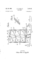
FIGURE 4 is avertical section, part in elevation, of a modified form of the solar motor.
In the drawings like characters of reference indicate corresponding parts in each figure.
The solar motor is provide with a stator, generally indicated by the numeral 10, and consisting of a circular base 11 of wood or reinforced plastic. Mounted on the base 11 isa centrally disposed vertical support 12 which is tted at its top end with a seat 14. This seat encloses a suitable bearing, not shown, which may be a diamond or glass, for example.
Enclosing the support 12 for a greater part of its height is an open-ended cylinder 16, preferably of clear transparent, plastic, which cylinder is securely aixed to the base 11. A number of equidistantly spaced inlet vanes 17 are mounted on the base, which vanes may be formed of very thin transparent plastic. The vertical vanes 17 are above the base 11 to permit air to enter between the vanes.
The stator supports a rotor 20 consisting of inner and outer concentrically disposed cylinders 21 and 22 respectively. Both these cylinders are open-ended structures and a clear, transparent and very thin plastic is used in their construction. The lower edges of the cylinders 21 and 22 are connected by a number of circumferentially spaced sticks 24. The upper end of the inner cylinder 21 is bridged by four radial arms 25. A steel pivot pin 27 is secured to the underside of the arms at the centre of the inner cylinder and the tip of this pin is journalled in the bearing carried bythe seat 14.
The rotor 20 is fitted with several vanes 29, the lower edges of which are secured to the sticks 24. These vanes extend upwardly from their supporting sticks at an angle ice of substantially 45 to a horizontal plane and the side edges of said vanes may be suitably secured to the peripheries of the cylinders 21 and 22. i
Referring now to FIG. 3 it will be seen that the vanes 29 are of laminate construction and are made up of three layers A, B and C. The bottom layer C is the thinnest commercially sold aluminum which is a good conductor of heat. Layer B is a semi-conductor of heat and is made up by mixing the following materials in the proportions noted:
2 parts carbon (powder form) 1 part lamp black (powder form) 4 parts metal lacquer (liquid) allow the suns radiant energy therethrough. To formv layer A one of the following materials may be used, clear varnish, lacquer, enamel or plastic.l This is applied to the dried layer B as a spray, a single thin coat only being applied and allowed to dry for approximately two days.
In the above described manner the vanes 29 are constructed to form what might be referred to as an absorbent transformer since the vanes are designed to absorb the suns radiant energy and transform it into heat energy.
When assembling the vanes in the rotor great care should,
be taken not to tough the underside of the aluminum layer C since nger grease will cut down the eiciency of the Y unit. The thickness of the vanes 29 is less than .015 of a millimeter but this has been found to provide sufficient structural strength. If the cost of the vanes is not a consideration andeven greater efficiency is desired layer C can be made of silver, layer B of silicon (treated with lamp black or the like to improve its heat absorbent qualities) and layer A can be formed of boron.
The modified form of the solar motor shown in FIG. 4 has a stator consisting of a base 111, cylinder 161, vanes 171, and an outer cylinder 181 all of which are constructed substantially as before. A cone-shaped extension 35 is fitted to the top of the cylinder 181 which extension is intended to give a Venturi effect to the air owing upwardly through said cylinder. The cylinder 181 is fitted at each open end with reinforcing spokes 37 which are formed preferably of thin aluminum tubing. A roller bearing 38 is provided at the hub formed by the radial spokes at each end of the cylinder.
Journalled in the bearings 38 is the tubular aluminum shaft 40 of a modified stator 41. In this instance the stator has an inner cylinder 211 only and the vanes 291 are helically wound around this cylinder and are suitably secured. thereto. The outer edges of the vanes are reinforced by thin wooden strips 43 and at suitable intervals said strips are supported by vertically spaced strips 44, also of thin wood. The strips 44 are horizontally and radially disposed and extend through the cylinder 211 for connection to the shaft 40. Thus a strong lightweight rotor is constructed and it will be noted that the clearance between the strips 43 and the inner periphery of the cylinder 181 is made as small as possible.
Beneath the lower bearing 38 a crank 47 is fitted to the shaft 40 and said crank is connected by a rod 48 to the operating handle 49 of a water pump 50. The pump may be intended to draw water from a well and discharge it into a container 51. However this mechanism is shown only as an example of the use to which the solar motor may be put and detailed description is deemed unnecessary.
A fence 54 may be erected around the base of the motor on the side or sides of the prevailing winds to protect tbe thin it heats very quickly and being a semi-conductor of` heat also heats fairly evenly throughout. Layer AV which is a relatively poor conductor of heat will restrict heat ow in an upward direction and in doing so will achieve what might be referred to as a greenhouse effect. Thus the heat in layer B will ow into layer C which is a good conductor of heat and since it has this property will readily heat the air immediately below the vanes.
The air heated in this manner expands and tends to rise by convection and in doing so will exert a pressure on the underside of the rotor vanes so as to rotate the rotor in the direction of the arrow 56 of FIG. 1. The ow of air through the motor is indicated by the chain dotted arrows 57 of FIGS. 2 and 4. If a wind is blowing near ground lever, as shown by the dotted arrows 58 of FIGS. 2 and 4, this ground wind is directed by the vanes 17 so as to flow upwardly and augment the driving force applied to the vanes 29 by the convection currents. The rotor continues to revolve at a fairly constant speed as long as the heat affects the rotor vanes. The reaction is the same but not as strong whenv articial light is applied to these vanes.
The cylinders 21 and 22V prevent the rising air from escaping to the side and the space between the cylinder 22 and the stator cylinder 18v provide for by-pass cooling.
It should be mentioned here that force of pressure created by the expansion of air being heated beneath the vanes is of little significance as compared to the force ofthe lifting heated air (as the principle used in the radiometer).
What is claimed in my invention:
l. In a solar motor having a rotor tted with vanes adapted to impart rotation to the rotor in response to thermal currents moving substantially parallel to the longitudinal axis of the rotor, Vsaid vanes comprising a bottom, intermediate and top layer, said bottom layer being a good conductor of heat, said intermediate layer being a fair conductor of heat and said top layer being a poor conductor of heat whereby solar heat is amplified by the top layer for storage in the intermediate layer and subsequent transfer by the bottom layer to the air beneath the rotor vane.
2. Structure as claimed in claim 1 wherein the bottom layer is a very thin sheet of metallic material.
3. Structure as claimed in claim 2, wherein the intermediate layer is a relatively thick sheet of opaque material. f
. 4. Structure as claimed in claim 3, wherein the top layer is a coating of transparent material."
References Cited in the file of this patent UNITED STATES PATENTS` 2,597,890 Monk May 27, 1952 3,031,852 White May 1, 1962 3,048,006 Goodman Aug. 7, 1962 FOREIGN PATENTS 1,109,568 France Sept. 28, 1955
Claims (1)
1. IN A SOLAR MOTOR HAVING A ROTOR FITTED WITH VANES ADAPTED TO IMPART ROTATION TO THE ROTOR IN RESPONSE TO THERMAL CURRENTS MOVING SUBSTANTIALLY PARALLEL TO THE LONGITUDINAL AXIS OF THE ROTOR, SAID VANES COMPRISING A BOTTOM, INTERMEDIATE AND TOP LAYER, SAID BOTTOM LAYER BEING A GOOD CONDUCTOR OF HEAT, SAID INTERMEDIATE LAYER BEING A FAIR CONDUCTOR OF HEAT AND SAID TOP LAYER BEING A POOR CONDUCTOR OF HEAT WHEREBY SOLAR HEAT IS AMPLIFIED BY THE TOP LAYER FOR STORAGE IN THE INTERMEDIATE LAYER AND SUB-
Priority Applications (1)
| Application Number | Priority Date | Filing Date | Title |
|---|---|---|---|
| US175846A US3137125A (en) | 1962-02-26 | 1962-02-26 | Solar motor |
Applications Claiming Priority (1)
| Application Number | Priority Date | Filing Date | Title |
|---|---|---|---|
| US175846A US3137125A (en) | 1962-02-26 | 1962-02-26 | Solar motor |
Publications (1)
| Publication Number | Publication Date |
|---|---|
| US3137125A true US3137125A (en) | 1964-06-16 |
Family
ID=22641888
Family Applications (1)
| Application Number | Title | Priority Date | Filing Date |
|---|---|---|---|
| US175846A Expired - Lifetime US3137125A (en) | 1962-02-26 | 1962-02-26 | Solar motor |
Country Status (1)
| Country | Link |
|---|---|
| US (1) | US3137125A (en) |
Cited By (11)
| Publication number | Priority date | Publication date | Assignee | Title |
|---|---|---|---|---|
| US3279457A (en) * | 1964-12-28 | 1966-10-18 | William F Kyryluk | Solar heat concentrator |
| US4118636A (en) * | 1976-11-26 | 1978-10-03 | Christian Merlin B | Thermal air powered electric generator system |
| US4353003A (en) * | 1980-11-17 | 1982-10-05 | Dale Sommers | Solar electric generator |
| US5300817A (en) * | 1993-04-16 | 1994-04-05 | Baird William R | Solar venturi turbine |
| WO1994022435A1 (en) * | 1993-04-02 | 1994-10-13 | Orion-Yhtymä Oy | A new composition containing selegiline |
| US5552685A (en) * | 1993-08-18 | 1996-09-03 | General Electric Company | Apparatus and method for detection and control of circulating currents in a variable speed DC motor |
| US5675231A (en) * | 1996-05-15 | 1997-10-07 | General Electric Company | Systems and methods for protecting a single phase motor from circulating currents |
| WO1999044841A1 (en) * | 1998-03-02 | 1999-09-10 | Andreas Biedermann | Crookes' radiometer or vane radiometer |
| US20040148933A1 (en) * | 2003-01-30 | 2004-08-05 | Miller Larry D. | Solar-thermal powered generator |
| US20140203566A1 (en) * | 2011-05-18 | 2014-07-24 | Hong Yuan | Wind turbine |
| US11767828B2 (en) | 2023-03-27 | 2023-09-26 | Daniel L. Amend | Light turbine, turbine, and turbine housing for vane evaluation |
Citations (4)
| Publication number | Priority date | Publication date | Assignee | Title |
|---|---|---|---|---|
| US2597890A (en) * | 1949-12-20 | 1952-05-27 | Monk Ivan | Rotary power unit operable on atmospheric energy |
| FR1109568A (en) * | 1954-07-31 | 1956-01-31 | Device for transforming solar energy into mechanical or other energy | |
| US3031852A (en) * | 1958-02-06 | 1962-05-01 | Walter W White | Radiation turbine |
| US3048006A (en) * | 1960-12-27 | 1962-08-07 | Alexander J E Beard | Thermal current driven power generating apparatus |
-
1962
- 1962-02-26 US US175846A patent/US3137125A/en not_active Expired - Lifetime
Patent Citations (4)
| Publication number | Priority date | Publication date | Assignee | Title |
|---|---|---|---|---|
| US2597890A (en) * | 1949-12-20 | 1952-05-27 | Monk Ivan | Rotary power unit operable on atmospheric energy |
| FR1109568A (en) * | 1954-07-31 | 1956-01-31 | Device for transforming solar energy into mechanical or other energy | |
| US3031852A (en) * | 1958-02-06 | 1962-05-01 | Walter W White | Radiation turbine |
| US3048006A (en) * | 1960-12-27 | 1962-08-07 | Alexander J E Beard | Thermal current driven power generating apparatus |
Cited By (14)
| Publication number | Priority date | Publication date | Assignee | Title |
|---|---|---|---|---|
| US3279457A (en) * | 1964-12-28 | 1966-10-18 | William F Kyryluk | Solar heat concentrator |
| US4118636A (en) * | 1976-11-26 | 1978-10-03 | Christian Merlin B | Thermal air powered electric generator system |
| US4353003A (en) * | 1980-11-17 | 1982-10-05 | Dale Sommers | Solar electric generator |
| WO1994022435A1 (en) * | 1993-04-02 | 1994-10-13 | Orion-Yhtymä Oy | A new composition containing selegiline |
| US5381048A (en) * | 1993-04-16 | 1995-01-10 | Baird; William R. | Solar venturi turbine |
| WO1994024435A1 (en) * | 1993-04-16 | 1994-10-27 | Baird William R | Solar venturi turbine |
| US5300817A (en) * | 1993-04-16 | 1994-04-05 | Baird William R | Solar venturi turbine |
| US5552685A (en) * | 1993-08-18 | 1996-09-03 | General Electric Company | Apparatus and method for detection and control of circulating currents in a variable speed DC motor |
| US5675231A (en) * | 1996-05-15 | 1997-10-07 | General Electric Company | Systems and methods for protecting a single phase motor from circulating currents |
| WO1999044841A1 (en) * | 1998-03-02 | 1999-09-10 | Andreas Biedermann | Crookes' radiometer or vane radiometer |
| US20040148933A1 (en) * | 2003-01-30 | 2004-08-05 | Miller Larry D. | Solar-thermal powered generator |
| US7340898B2 (en) | 2003-01-30 | 2008-03-11 | Miller Larry D | Solar-thermal powered generator |
| US20140203566A1 (en) * | 2011-05-18 | 2014-07-24 | Hong Yuan | Wind turbine |
| US11767828B2 (en) | 2023-03-27 | 2023-09-26 | Daniel L. Amend | Light turbine, turbine, and turbine housing for vane evaluation |
Similar Documents
| Publication | Publication Date | Title |
|---|---|---|
| US3137125A (en) | Solar motor | |
| US5463257A (en) | Wind power machine | |
| US4077392A (en) | Novel solar collector | |
| US5336933A (en) | Fluid-augmented free-vortex power generating apparatus | |
| US6935841B2 (en) | Fan assembly | |
| US2247830A (en) | Solar heater | |
| CN110240211A (en) | Solar energy thermal transition purifier and process for purifying water | |
| US4406579A (en) | Airflow converter | |
| NO753023L (en) | ||
| US5103646A (en) | Solar and wind powered generator | |
| US4331042A (en) | Solar generator | |
| US20090174192A1 (en) | Turbulence reduction around magnus rotors | |
| DE10217529B4 (en) | Eddy current power plant | |
| GB2062107A (en) | Turbine Driven Generator | |
| US4141218A (en) | Buoyancy operated Sunmill | |
| US10385824B2 (en) | Wind turbine | |
| RU2210000C1 (en) | Rotary windmill | |
| FR2461832A1 (en) | Combined wind and solar powered energy generator - uses turbine within flow casing painted black for solar heat absorption | |
| CN109442906B (en) | Drying device of chinese-medicinal material that can increase sunning efficiency | |
| CN201209518Y (en) | Wind wheel with bonnet and guiding device | |
| CN206399001U (en) | A kind of scene is driven from motion tracking solar energy heat collector | |
| US1576373A (en) | Power generator | |
| FR2461119A1 (en) | Vertical axis wind vane - has set of aerofoil sails orientated by connecting rods to give desired angle of attack | |
| CN212225441U (en) | New energy wind energy and solar energy utilization device | |
| RU221765U1 (en) | Wind turbine rotor |