US3122166A - Multiway valve and fluid pressure seal therefor - Google Patents
Multiway valve and fluid pressure seal therefor Download PDFInfo
- Publication number
- US3122166A US3122166A US13191261A US3122166A US 3122166 A US3122166 A US 3122166A US 13191261 A US13191261 A US 13191261A US 3122166 A US3122166 A US 3122166A
- Authority
- US
- United States
- Prior art keywords
- fluid
- ports
- drum
- mating surfaces
- punch
- Prior art date
- Legal status (The legal status is an assumption and is not a legal conclusion. Google has not performed a legal analysis and makes no representation as to the accuracy of the status listed.)
- Expired - Lifetime
Links
Images

Classifications
-
- F—MECHANICAL ENGINEERING; LIGHTING; HEATING; WEAPONS; BLASTING
- F15—FLUID-PRESSURE ACTUATORS; HYDRAULICS OR PNEUMATICS IN GENERAL
- F15C—FLUID-CIRCUIT ELEMENTS PREDOMINANTLY USED FOR COMPUTING OR CONTROL PURPOSES
- F15C1/00—Circuit elements having no moving parts
- F15C1/02—Details, e.g. special constructional devices for circuits with fluid elements, such as resistances, capacitive circuit elements; devices preventing reaction coupling in composite elements ; Switch boards; Programme devices
-
- F—MECHANICAL ENGINEERING; LIGHTING; HEATING; WEAPONS; BLASTING
- F15—FLUID-PRESSURE ACTUATORS; HYDRAULICS OR PNEUMATICS IN GENERAL
- F15B—SYSTEMS ACTING BY MEANS OF FLUIDS IN GENERAL; FLUID-PRESSURE ACTUATORS, e.g. SERVOMOTORS; DETAILS OF FLUID-PRESSURE SYSTEMS, NOT OTHERWISE PROVIDED FOR
- F15B21/00—Common features of fluid actuator systems; Fluid-pressure actuator systems or details thereof, not covered by any other group of this subclass
-
- F—MECHANICAL ENGINEERING; LIGHTING; HEATING; WEAPONS; BLASTING
- F16—ENGINEERING ELEMENTS AND UNITS; GENERAL MEASURES FOR PRODUCING AND MAINTAINING EFFECTIVE FUNCTIONING OF MACHINES OR INSTALLATIONS; THERMAL INSULATION IN GENERAL
- F16J—PISTONS; CYLINDERS; SEALINGS
- F16J15/00—Sealings
- F16J15/44—Free-space packings
- F16J15/447—Labyrinth packings
- F16J15/4476—Labyrinth packings with radial path
-
- F—MECHANICAL ENGINEERING; LIGHTING; HEATING; WEAPONS; BLASTING
- F16—ENGINEERING ELEMENTS AND UNITS; GENERAL MEASURES FOR PRODUCING AND MAINTAINING EFFECTIVE FUNCTIONING OF MACHINES OR INSTALLATIONS; THERMAL INSULATION IN GENERAL
- F16K—VALVES; TAPS; COCKS; ACTUATING-FLOATS; DEVICES FOR VENTING OR AERATING
- F16K11/00—Multiple-way valves, e.g. mixing valves; Pipe fittings incorporating such valves
- F16K11/02—Multiple-way valves, e.g. mixing valves; Pipe fittings incorporating such valves with all movable sealing faces moving as one unit
- F16K11/06—Multiple-way valves, e.g. mixing valves; Pipe fittings incorporating such valves with all movable sealing faces moving as one unit comprising only sliding valves, i.e. sliding closure elements
- F16K11/072—Multiple-way valves, e.g. mixing valves; Pipe fittings incorporating such valves with all movable sealing faces moving as one unit comprising only sliding valves, i.e. sliding closure elements with pivoted closure members
- F16K11/074—Multiple-way valves, e.g. mixing valves; Pipe fittings incorporating such valves with all movable sealing faces moving as one unit comprising only sliding valves, i.e. sliding closure elements with pivoted closure members with flat sealing faces
-
- F—MECHANICAL ENGINEERING; LIGHTING; HEATING; WEAPONS; BLASTING
- F16—ENGINEERING ELEMENTS AND UNITS; GENERAL MEASURES FOR PRODUCING AND MAINTAINING EFFECTIVE FUNCTIONING OF MACHINES OR INSTALLATIONS; THERMAL INSULATION IN GENERAL
- F16L—PIPES; JOINTS OR FITTINGS FOR PIPES; SUPPORTS FOR PIPES, CABLES OR PROTECTIVE TUBING; MEANS FOR THERMAL INSULATION IN GENERAL
- F16L39/00—Joints or fittings for double-walled or multi-channel pipes or pipe assemblies
- F16L39/06—Joints or fittings for double-walled or multi-channel pipes or pipe assemblies of the multiline swivel type, e.g. comprising a plurality of axially mounted modules
-
- G—PHYSICS
- G05—CONTROLLING; REGULATING
- G05B—CONTROL OR REGULATING SYSTEMS IN GENERAL; FUNCTIONAL ELEMENTS OF SUCH SYSTEMS; MONITORING OR TESTING ARRANGEMENTS FOR SUCH SYSTEMS OR ELEMENTS
- G05B19/00—Programme-control systems
- G05B19/43—Programme-control systems fluidic
- G05B19/44—Programme-control systems fluidic pneumatic
-
- Y—GENERAL TAGGING OF NEW TECHNOLOGICAL DEVELOPMENTS; GENERAL TAGGING OF CROSS-SECTIONAL TECHNOLOGIES SPANNING OVER SEVERAL SECTIONS OF THE IPC; TECHNICAL SUBJECTS COVERED BY FORMER USPC CROSS-REFERENCE ART COLLECTIONS [XRACs] AND DIGESTS
- Y10—TECHNICAL SUBJECTS COVERED BY FORMER USPC
- Y10T—TECHNICAL SUBJECTS COVERED BY FORMER US CLASSIFICATION
- Y10T137/00—Fluid handling
- Y10T137/8593—Systems
- Y10T137/86493—Multi-way valve unit
- Y10T137/86558—Plural noncommunicating flow paths
- Y10T137/86566—Rotary plug
Definitions
- the present invention relates to means for providing a fluid pressure seal, and more particularly to means whereby isolation may be accomplished, one from another, between a plurality of fluid passageways temporarily formed in members having relative motion therebetween.
- in- Vention disclosed herein is adapted to isolate a plurality of high pressure fluid lines one from another in the case where such lines have points of discontinuity occuring at the clearance between the members.
- an object of the present invention is to provide sealing means isolating each of a plurality of temporarily formed fluid passageways one from another, where each said passageway comprises first and second ducts terminated in ports respectively located in first and second mating surfaces having relative motion therebetween.
- Another object of the present invention is to provide sealing means between points of discontinuity in adjacent fluid pressure lines which comprises a labyrinthian corridor between said points of discontinuity, together with lubricant located therein to develop a film which prevents leakage of fluid.
- This invention is particularly adapted to provide means for making a plurality of fluid connections to a rotating drum without the intermixing of said connections. It may therefore be utilized as the sealing means between the rotatin' punch drum and stationary face plate of the card punch disclosed in pending U.S. application Serial No. 54,086, now Patent Number 3,059,842 filed September 6, 1960. n this application, O-ring seals or the like are employed to prevent the leakage of fluid from one high pressure control line into another or into the outside environrnent. However, the present invention provides a more positive type seal without causing any friction loss between the adjacent surfaces of the rotating drum and stationary plate.
- FIGURE 1 shows the use of the present invention a card punch environment
- FIGURE 2 discloses a detailed sectional view of the present invention.
- FIGURE 3 shows another sectional view of the invention.
- FIGURE 4 shows a pictorial section view of the invention.
- FIGURE 1 of the drawings is a sectional view of the punch and die drums according to the invention disclosed and claimed in said above identified pending application and in which the present invention is particularly useful.
- the punch drum it comprises a substantially solid body surrounding a hollow core 62.
- a plurality of punches 60 are contained within the solid portion of drum it! and arranged in a plurality of longitudinally extending rows circumferentially spaced about the periphery thereof.
- the number of punch rows depends upon the coding system employed and may, for example, consist of ten rows to enable the representation of numerical digits 0 through 9.
- the punches also are arranged in columns around the periphery of the drum so that one punch of each row lies in the same column as the corresponding punch of each of the other rows. For purposes of illustration only, three columns I, Ii, and Hi have been shown, but it is obvious to those skilled in the art that the number of columns is determined only by the number of character columns to be punched on the card.
- the die drum 14 comprises an outer shell surrounding a hollow interior.
- the outer shell contains a plurality of holes 64, one for each of the punches 60.
- the punch and die drums are axially aligned with and capable of receiving successive punches iii if the punches are extended through a card 12 passing between them.
- Bearings 66 and 58 mounted in stationary side plate permit the punch and die drums 10 and 14, respectively, to be continuously driven by means of shafts 72 and 74 from any suitable drive means not shown.
- control signal duct 26 is associated with the punch 63 lying in column I of the row directly adjacent die drum 14 in FIGURE 1.
- a pulse is applied via this control signal duct 26 to one inlet of punch 69, and the punch is extended so as to be inserted into its complementary die hole as in drum 14.
- punch se occurs when a pulse is subsequently applied via common duct 82 and individual duct 42 to a different inlet of the punch.
- An exhaust duct 48 is provided for each punch 66 to return the high pressure input pulses to the fluid source and thus create a closed system.
- one or more of the punches 6i lying in the row directly adjacent die drum 14 may be extended simultaneously if the same character must be recorded in more than one of the card columns.
- Each of the control signal ducts 26 in each group terminates at a port or opening '76 in the end surface 7% of punch drum 1-3.
- Each of the exhaust ducts 48 is connected to the hollow interior of drum 1% Which in turn is connected via the passageway 89 in shaft 72 to the low pressure side of the external fluid supply 93.
- the control ducts 42 for each row of punches are connected to a common duct 82, as above described, which also terminates in a port 81 in the end surface 78.
- a plurality of control signal input ducts 94 ⁇ equal in number to the ports 76 in any one of the groups, pass through the stationary side plate 79 and terminate at ports 92 in the inner plate surface
- Each port 92 of which there are three shown, is located a distance from axis 72 so that it will be successively aligned with a corresponding port 76 in each of the groups as the punch drum rotates.
- port 522 successively aligns with the port 76 in each of the ten group
- ports 92 spective' ducts 90 and 25 simultaneously align with the ports 76 belonging to the punch row directly adjacent the card, in order that actuating fluid pulses may be simultaneously applied to two or more punches.
- the control signal input ducts 90 are connected through a selective control device 91 to the high pressure side of the fluid supply 93.
- the selective control device may, for example, be one of the many types of pneumatic card sensing devices well-known in the art and does not comprise a part of the present invention.
- a single control duct 94 passes through the stationary side plate 70 and terminates at port 96 in the surface 88 thereof. Port 96 can be located a distance from axis '72 so that it will be successively aligned with each of the ports 31 as the drum rotates at times slightly subsequent to the alignment of ports 92 with ports 76 of corresponding punch rows.
- Each such passageway is comprised of two ducts, 9i) and 26, which are respectively located in members having relative motion therebetween.
- duct 90 is located in stationary plate 70, and the corresponding duct is located 'in drum 10.
- each of said temporarily formed passageways has a point of discontinuity occurring at the ports 92 and '76 of its re- Inasmuch as a certain minimum clearance is desirable between the drum 10 and plate '70 to avoid wear of the mating surfaces 88 and 78 and to reduce friction loss, pulses traversing the clearance distance between ports 92) and i6 may leak into the space between said mating surfaces. Any fluid thus escaping from its passageway may travel to either the outside environment, or to the ports i6 or 76 of the adjacent temporarily formed passageways. Any of these alternatives is undesirable, since, for example, a punch 60' may be falsely actuated by such leakage fluid entering an adjacent passageway.
- the mating surfaces 88 and 78 are interleaved according to the present invention in such a manner to form a labyrinthian corridor between the port locations of adjacent passageways.
- a lubricant is located within the corridors thus formed such that when the drum is rotating at its operating speed,
- FIGURE 2 is an enlarged View of the lower. left portion of drum 10 and plate 70.
- the end mating surface 78 of drum-10 is formed in a plurality of ridges or protrusions 101 through 105 which have basically a rectangular cross-section in the preferred embodiment, although not limited thereto. These protrusions are concentric about the axis of drum rotation. Between adjacent pairs of protrusions 1%1 through 155. are corresponding valleys in which are located the ports 76 and 81 of respective ducts 26 and 82.
- Mating surface 88 of stationary plate 7il is likewise formed in a plurality-of matching and complementary concentric protrusions 106 through 109 having corresponding valleys therebetween into which are interleaved protrusions 101' through 105. of drum' it
- the clearance between mating surfaces 88 and 78 should be quite small and precise, being generally on the order of 0.001
- Ducts 9tliand 94 have respective ports 92 and 96 located in the 4 said last named ports and various ones of ports 26 and 81 will occur as drum 10 rotates.
- mating surfaces 88 and 78 have relative motion therebetween only in a direction normal to the plane of the paper. No matter what the angular position of drum 10, surfaces 83 and 78 are interleaved in such a manner that a corridor is maintained between pairs of associated ports QZP/l' and 92+ /76+ of adjacent temporarily formed passageways. Each corridor thus partially isolates the adjacent passageways one from the other by creating a tortuous route through which any leakage fluid must pass.
- the present invention includes a positive means of isolating the fluid passages.
- a lubricant is located within the labyrinthian corridors so formed between the mating surfaces 88 and 78.
- a hydrodynamic film 8 develops between the stationary and moving mating surfaces. This film blocks the leakage of any relatively high pressure pulse fluid from the passageway ports through a corridor into the ports of an adjacent passageway. T herer'ore, each of the pas sageways is isolated one from another. Well substantiated theory has shown that the film thickness formed within the corridor is directly proportional to the lubricant viscosity and speed of the moving surface, and inversely proportional to the drag force exerted by the fluid on the moving surface.
- the a ove may be mathematically expressed by the following equation:
- the range of clearances between the mating surfaces 88 and 78 may be of the order of 0.001" to 0.010". Ordinarily, this range would be much smaller if the mating surfaces carried a load. environment shown, that of providing isolation between the high pressure passageways in a card punch, no load 7 is present on these surfaces since bearing as supports drum 10 in stationary plate 70. Therefore, the clearance can be larger and still maintain an unbroken film therein.
- the invention is capable of use in apparatus having a relatively wide range of operating speeds.
- FIGURE 3 of the drawings illustrates a viewof the end surface of drum 10 taken in section along A-A' in FIG- URE 2.
- This figure emphasizes the concentric ring construction of the protruded e'nd surfaces, as well as showing the radial arrangement of the groups of ports 76 and 81 associated with the punch rows.
- the shapes of these ports are preferably rectangular in the direction of motion, or some other suitable shape, in order to provide flexibility of punch timing.
- FIGURE/1 is a pictorial sectional view straight parallel protrusionsinstead of the circular concentric protrusions necessary in the card punch device. Many other modifications may likewise be evident to one skilled in the art without departing from the spirit of the invention as defined in the appended claims.
- each said passageway comprises first and second ducts terminated in ports respectively located in first and second mating surfaces, with said mating surfaces being adjacent and having means for producing relative velocity between said surfaces to selectively align the ports of corresponding first and second ducts of the same passageway to allow the transmission or" relatively high pressure fluid therethrough
- said sealing means comprising; a labyrinthian corridor between the port locations of each suc essive pair of fiuid passageways, said corridor being formed by an interleaving or" said first and second mating surfaces, and lubricant located within said corridors between said mating surfaces, said velocity producing means producing a velocity of sufficient magnitude to establish a hydrodynamic film to thereby prevent leakage of fluid between the ports of adjacent passageways.
- Apparatus comprising a first member one surface of which has a portion formed in a first plurality of parallel protrusions and corresponding valleys therebetween, a second member one surface of which has a portion formed in a second plurality of parallel protrusions and corresponding valleys therebetwe-en, which are complementary to and interleaved with said first plurality so as to mate with respective ones of said first member valleys and vice versa, means for producing relative velocity between said first and second member surfaces, at least one port located in each of said second member protrusions for the b passage of relatively high pressure fluid therethrough, at least one port located in each of said first member valleys for the passage of relatively high pressure fluid therethrough and with which the correspond ng interleaved protrusion port matches as one of said members moves with espect to the other, and lubricant located within each region where said first member protrusions mate with said second member valleys, said velocity producing means producing a velocity or" sulficient magnitude to establish a hydrodynamic film between
- one of said members has a plurality of high pressure ports lo cated in each of its respective surfaces, each port of a said plurality being successively matched with the port of the corresponding mating surface of the other member as they move with respect to each other.
- Apparatus comprising a rotatable drum one end surrace of which has a portion formed in a first plurality of protrusions and corresponding vall ys therebetween, which are concentric about its axis of rotation, a stationary side plate one surface or" which has a portion formed in a second plurality of concentric protrusions and corresponding valleys therebetween which are complementary to and interleaved with said first plurality so as to mate with respective ones of said drum valleys and vice versa, at least one port located in each of said stationary plate protrusions for the passage of relatively high pressure fluid therethrough, at least one port located in each of said drum valleys for the passage of relatively hi h pressure fluid therethrongh and with which the correspond ing interleaved stationary protrusion port matches as said drum rotates in order to transfer fluid therebetween, lubricant located within each region where said drum protrusions mate with said stationary plate valleys which serves to establish a hydrodynamic film etween said mating surfaces to thereby prevent
- each of said drum valleys has a plurality of ports each of which successively matches with the corresponding stationary protrusion port as said drum rotates.
Description
Feb. 25, 1964 E. M. POLTER 3,122,156
MULTIWAY VALVE AND FLUID PRESSURE SEAL THEREFOR Filed Aug. 16, 1961 2 Sheets-Sheet 1 94 I F if 90 I SELECTOR F a INVENTOR.
SUPPLY kl fllfi/f M mm BY k- .1 I J MM A TTORNE Y6 E. M. POLTER 3,122,166
MULTIWAY VALVE AND FLUID PRESSURE SEAL THEREFOR Feb. 25, 1964 2 Sheets-Sheet 2 Filed Aug. 16, 1961 United States Patent Oflfice 3,122,1hfi Patented Feb. 25, 1964 3,122,166 h EULTIWAY VALVE AND FLUID PRESSURE SEAL THEREFOR Eugene M. Polter, Philadelphia, Pa., assignor to Sperry Rand Corporation, New York, N.Y., a corporation of Delaware Filed Au 15, 1961, Ser. No. 131,912 13 Claims. (Cl. 137-4251?) The present invention relates to means for providing a fluid pressure seal, and more particularly to means whereby isolation may be accomplished, one from another, between a plurality of fluid passageways temporarily formed in members having relative motion therebetween.
In the rapidly developing field of fluid amplifier data processing systems, wherein digital control and information pulses are transmitted in a fluid medium, it is often desirable to transfer fluid pulses between mechanical members having relative motion therebetween. The in- Vention disclosed herein is adapted to isolate a plurality of high pressure fluid lines one from another in the case where such lines have points of discontinuity occuring at the clearance between the members.
Therefore, an object of the present invention is to provide sealing means isolating each of a plurality of temporarily formed fluid passageways one from another, where each said passageway comprises first and second ducts terminated in ports respectively located in first and second mating surfaces having relative motion therebetween.
Another object of the present invention is to provide sealing means between points of discontinuity in adjacent fluid pressure lines which comprises a labyrinthian corridor between said points of discontinuity, together with lubricant located therein to develop a film which prevents leakage of fluid.
This invention is particularly adapted to provide means for making a plurality of fluid connections to a rotating drum without the intermixing of said connections. It may therefore be utilized as the sealing means between the rotatin' punch drum and stationary face plate of the card punch disclosed in pending U.S. application Serial No. 54,086, now Patent Number 3,059,842 filed September 6, 1960. n this application, O-ring seals or the like are employed to prevent the leakage of fluid from one high pressure control line into another or into the outside environrnent. However, the present invention provides a more positive type seal without causing any friction loss between the adjacent surfaces of the rotating drum and stationary plate.
it is therefore anot ler object of the present invention to provide sealing means between a number of fluid pressure lines interconnected between a rotating drum member and a stationary face plate.
These and other objects of the present invention will be apparent during the course of the following description, which is to be taken in conjunction with the drawings, in which:
FIGURE 1 shows the use of the present invention a card punch environment;
FIGURE 2 discloses a detailed sectional view of the present invention.
FIGURE 3 shows another sectional view of the invention; and
FIGURE 4 shows a pictorial section view of the invention.
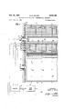
FIGURE 1 of the drawings is a sectional view of the punch and die drums according to the invention disclosed and claimed in said above identified pending application and in which the present invention is particularly useful. The punch drum it comprises a substantially solid body surrounding a hollow core 62. A plurality of punches 60 are contained within the solid portion of drum it! and arranged in a plurality of longitudinally extending rows circumferentially spaced about the periphery thereof. The number of punch rows depends upon the coding system employed and may, for example, consist of ten rows to enable the representation of numerical digits 0 through 9. The punches also are arranged in columns around the periphery of the drum so that one punch of each row lies in the same column as the corresponding punch of each of the other rows. For purposes of illustration only, three columns I, Ii, and Hi have been shown, but it is obvious to those skilled in the art that the number of columns is determined only by the number of character columns to be punched on the card.
The die drum 14 comprises an outer shell surrounding a hollow interior. The outer shell contains a plurality of holes 64, one for each of the punches 60. The punch and die drums are axially aligned with and capable of receiving successive punches iii if the punches are extended through a card 12 passing between them. Bearings 66 and 58 mounted in stationary side plate permit the punch and die drums 10 and 14, respectively, to be continuously driven by means of shafts 72 and 74 from any suitable drive means not shown.
As explained in said above identified pending application, in order to energize any of the punches 69, a relatively high pressure pulse is applied thereto via its associated control signal duct 26. There is a group of ducts 26 for each punch row, each group containing as many ducts as there are punches in the row. For example, control signal duct 26 is associated with the punch 63 lying in column I of the row directly adjacent die drum 14 in FIGURE 1. When it is desired to energize punch 69, a pulse is applied via this control signal duct 26 to one inlet of punch 69, and the punch is extended so as to be inserted into its complementary die hole as in drum 14. The retraction of punch se occurs when a pulse is subsequently applied via common duct 82 and individual duct 42 to a different inlet of the punch. An exhaust duct 48 is provided for each punch 66 to return the high pressure input pulses to the fluid source and thus create a closed system. As explained in the above identified pending application, one or more of the punches 6i lying in the row directly adjacent die drum 14 may be extended simultaneously if the same character must be recorded in more than one of the card columns. Thus, there may be two or more high pressure pulses simultaneously existing in the group of control signal ducts 26 associated with a punch row adjacent to the card.
Each of the control signal ducts 26 in each group terminates at a port or opening '76 in the end surface 7% of punch drum 1-3. Thus, for the embodiment being described, there are ten groups of three ports 76 spaced radially about axis '72. Each of the exhaust ducts 48 is connected to the hollow interior of drum 1% Which in turn is connected via the passageway 89 in shaft 72 to the low pressure side of the external fluid supply 93. The control ducts 42 for each row of punches are connected to a common duct 82, as above described, which also terminates in a port 81 in the end surface 78. Thus, there are a total of ten ports 31 spaced about the drum axis 72 for the embodiment under consideration.
A plurality of control signal input ducts 94}, equal in number to the ports 76 in any one of the groups, pass through the stationary side plate 79 and terminate at ports 92 in the inner plate surface Each port 92 of which there are three shown, is located a distance from axis 72 so that it will be successively aligned with a corresponding port 76 in each of the groups as the punch drum rotates. Thus, port 522 successively aligns with the port 76 in each of the ten group However, ports 92 spective' ducts 90 and 25 simultaneously align with the ports 76 belonging to the punch row directly adjacent the card, in order that actuating fluid pulses may be simultaneously applied to two or more punches. The control signal input ducts 90 are connected through a selective control device 91 to the high pressure side of the fluid supply 93. The selective control device may, for example, be one of the many types of pneumatic card sensing devices well-known in the art and does not comprise a part of the present invention. A single control duct 94 passes through the stationary side plate 70 and terminates at port 96 in the surface 88 thereof. Port 96 can be located a distance from axis '72 so that it will be successively aligned with each of the ports 31 as the drum rotates at times slightly subsequent to the alignment of ports 92 with ports 76 of corresponding punch rows.
From the above, it may be appreciated that as each punch row moves adjacent to card 12, a plurality of fluid passageways is temporarily formed each of which extends through end plate 70 and drum and through which a fluid pulse fromselector 91 may be applied to a punch 6%.
Each such passageway is comprised of two ducts, 9i) and 26, which are respectively located in members having relative motion therebetween. For example, duct 90 is located in stationary plate 70, and the corresponding duct is located 'in drum 10. However, each of said temporarily formed passageways has a point of discontinuity occurring at the ports 92 and '76 of its re- Inasmuch as a certain minimum clearance is desirable between the drum 10 and plate '70 to avoid wear of the mating surfaces 88 and 78 and to reduce friction loss, pulses traversing the clearance distance between ports 92) and i6 may leak into the space between said mating surfaces. Any fluid thus escaping from its passageway may travel to either the outside environment, or to the ports i6 or 76 of the adjacent temporarily formed passageways. Any of these alternatives is undesirable, since, for example, a punch 60' may be falsely actuated by such leakage fluid entering an adjacent passageway.
In order to prevent the leakage of fluid from one temporarily formed high pressure passageway to another because of the points of discontinuity engendered by the clearance between plate 7% and drum 10, the mating surfaces 88 and 78 are interleaved according to the present invention in such a manner to form a labyrinthian corridor between the port locations of adjacent passageways. A lubricant is located within the corridors thus formed such that when the drum is rotating at its operating speed,
' a hydrodynamic film develops between the stationary and moving surfaces within the corridors. This film blocks the leakage of high pressure pulse fluid into contiguous passageways, thereby isolating each pressure line. The details of these corridors are shown in FIGURE 2 which is an enlarged View of the lower. left portion of drum 10 and plate 70. The end mating surface 78 of drum-10 is formed in a plurality of ridges or protrusions 101 through 105 which have basically a rectangular cross-section in the preferred embodiment, although not limited thereto. These protrusions are concentric about the axis of drum rotation. Between adjacent pairs of protrusions 1%1 through 155. are corresponding valleys in which are located the ports 76 and 81 of respective ducts 26 and 82.
to 0.010, and may be maintained so'because' of the presence of bearing es "which prevents motionof drum 10 in a direction transverse to its axis of'rotation. Ducts 9tliand 94 have respective ports 92 and 96 located in the 4 said last named ports and various ones of ports 26 and 81 will occur as drum 10 rotates.
As shown in FIGURE 2, mating surfaces 88 and 78 have relative motion therebetween only in a direction normal to the plane of the paper. No matter what the angular position of drum 10, surfaces 83 and 78 are interleaved in such a manner that a corridor is maintained between pairs of associated ports QZP/l' and 92+ /76+ of adjacent temporarily formed passageways. Each corridor thus partially isolates the adjacent passageways one from the other by creating a tortuous route through which any leakage fluid must pass. However, the present invention includes a positive means of isolating the fluid passages. A lubricant is located within the labyrinthian corridors so formed between the mating surfaces 88 and 78. When the drum 10 is rotating at its operating speed, a hydrodynamic film 8 develops between the stationary and moving mating surfaces. This film blocks the leakage of any relatively high pressure pulse fluid from the passageway ports through a corridor into the ports of an adjacent passageway. T herer'ore, each of the pas sageways is isolated one from another. Well substantiated theory has shown that the film thickness formed within the corridor is directly proportional to the lubricant viscosity and speed of the moving surface, and inversely proportional to the drag force exerted by the fluid on the moving surface. The a ove may be mathematically expressed by the following equation:
As stated before, the range of clearances between the mating surfaces 88 and 78 may be of the order of 0.001" to 0.010". Ordinarily, this range would be much smaller if the mating surfaces carried a load. environment shown, that of providing isolation between the high pressure passageways in a card punch, no load 7 is present on these surfaces since bearing as supports drum 10 in stationary plate 70. Therefore, the clearance can be larger and still maintain an unbroken film therein. By merely changing the viscosity of the lubricant or the clearance betweenmating'surfaces 88 and. 78, the invention is capable of use in apparatus having a relatively wide range of operating speeds.
FIGURE 3 of the drawings illustrates a viewof the end surface of drum 10 taken in section along A-A' in FIG- URE 2. ,This figure emphasizes the concentric ring construction of the protruded e'nd surfaces, as well as showing the radial arrangement of the groups of ports 76 and 81 associated with the punch rows. The shapes of these ports are preferably rectangular in the direction of motion, or some other suitable shape, in order to provide flexibility of punch timing. FIGURE/1 is a pictorial sectional view straight parallel protrusionsinstead of the circular concentric protrusions necessary in the card punch device. Many other modifications may likewise be evident to one skilled in the art without departing from the spirit of the invention as defined in the appended claims.
In the particular I claim:
1. Sealing means for isolating each of a plurality of relatively high pressure fluid passageways one trom another, where each said passageway comprises first and second ducts terminated in ports respectively located in first and second mating surfaces, with said mating surfaces being adjacent and having means for producing relative velocity between said surfaces to selectively align the ports of corresponding first and second ducts of the same passageway to allow the transmission or" relatively high pressure fluid therethrough, said sealing means comprising; a labyrinthian corridor between the port locations of each suc essive pair of fiuid passageways, said corridor being formed by an interleaving or" said first and second mating surfaces, and lubricant located within said corridors between said mating surfaces, said velocity producing means producing a velocity of sufficient magnitude to establish a hydrodynamic film to thereby prevent leakage of fluid between the ports of adjacent passageways.
2. Sealing means according to claim 1 wherein the clearance between said mating surfaces is in the range from 0.001 inch to 0.010 inch, inclusive.
3. Seal ng means according to claim 1 wherein said rst mating surface is stationary and said second mat ng surface is in motion.
4. Sealing means according to claim 3 wherein the clearance between said mating surfaces is in the range from 0.001 inch to 0.010 inch, inclusive.
5. In apparatus having a moving first member one surface of which is adjacent to a surface of a stationary second member, said appmatus also having means for producing relative velocity between said surfaces during an index operation of said first member, where said stationary member contains a plu ality of first fluid ducts each terminated in a port located in its said surface and said moving member contains a plurality of second fluid ducts each terminated in a port located in its said surface at a position such as to be moved into alignment with a first duct port individual thereto during an ndex operation in order to form a passageway through said members for relatively high pr ssure fluid, the provision of sealing means for isolating each of said fluid passageways one from another, comprisin a labyrindlian corridor between the port positions or" each successive pair of fluid passageways, said corridor being formed by an interleaving of said adjacent first and second member surfaces, and lubricant located within said corridor, said velocity producing IIIBMIS producing a velocity of sutficient magnitude to establish a hydrodynamic film to thereby prevent leakage of fluid between the ports of adjacent passageways.
6. The invention according to claim 5 wherein the clearance between said mating surfaces is in the range from 0.001 inch to 0.010 inch, inclusive.
7. Apparatus comprising a first member one surface of which has a portion formed in a first plurality of parallel protrusions and corresponding valleys therebetween, a second member one surface of which has a portion formed in a second plurality of parallel protrusions and corresponding valleys therebetwe-en, which are complementary to and interleaved with said first plurality so as to mate with respective ones of said first member valleys and vice versa, means for producing relative velocity between said first and second member surfaces, at least one port located in each of said second member protrusions for the b passage of relatively high pressure fluid therethrough, at least one port located in each of said first member valleys for the passage of relatively high pressure fluid therethrough and with which the correspond ng interleaved protrusion port matches as one of said members moves with espect to the other, and lubricant located within each region where said first member protrusions mate with said second member valleys, said velocity producing means producing a velocity or" sulficient magnitude to establish a hydrodynamic film between said mating surfaces to thereby prevent leakage or" fiuid between the port locations of adjacent passageways.
8. Apparatus according to claim 7 wherein the cle ance between said mating surfaces is in the range from 0.001 inch to 0.0l0 inch, inclusive.
9. Apparatus according to claim 7 wherein one of said members has a plurality of high pressure ports lo cated in each of its respective surfaces, each port of a said plurality being successively matched with the port of the corresponding mating surface of the other member as they move with respect to each other.
10. Apparatus comprising a rotatable drum one end surrace of which has a portion formed in a first plurality of protrusions and corresponding vall ys therebetween, which are concentric about its axis of rotation, a stationary side plate one surface or" which has a portion formed in a second plurality of concentric protrusions and corresponding valleys therebetween which are complementary to and interleaved with said first plurality so as to mate with respective ones of said drum valleys and vice versa, at least one port located in each of said stationary plate protrusions for the passage of relatively high pressure fluid therethrough, at least one port located in each of said drum valleys for the passage of relatively hi h pressure fluid therethrongh and with which the correspond ing interleaved stationary protrusion port matches as said drum rotates in order to transfer fluid therebetween, lubricant located within each region where said drum protrusions mate with said stationary plate valleys which serves to establish a hydrodynamic film etween said mating surfaces to thereby prevent leakage of fluid between the ports of adjacent passageways when said drum is rotated at a predetermined minimum Velocity, and means for rotating said drum at least at said predetermined velocity to thereby establish said film.
11. Apparatus according to claim 10 wherein the clearance between said mating surfaces is in the range from 0.001 inch to 0.010 inch, inclusive.
12. Apparatus according to claim 10 wherein each of said drum valleys has a plurality of ports each of which successively matches with the corresponding stationary protrusion port as said drum rotates.
13. Apparatus according to claim 12 wherein the clearance between said mating surfaces is in the range from 0.001 inch to 0.010 inch, inclusive.
References Cited in the file of this patent UNITED STATES PATENTS
Claims (1)
1. SEALING MEANS FOR ISOLATING EACH OF A PLURALITY OF RELATIVELY HIGH PRESSURE FLUID PASSAGEWAYS ONE FROM ANOTHER, WHERE EACH SAID PASSAGEWAY COMPRISES FIRST AND SECOND DUCTS TERMINATED IN PORTS RESPECTIVELY LOCATED IN FIRST AND SECOND MATING SURFACES, WITH SAID MATING SURFACES BEING ADJACENT AND HAVING MEANS FOR PRODUCING RELATIVE VELOCITY BETWEEN SAID SURFACES TO SELECTIVELY ALIGN THE PORTS OF CORRESPONDING FIRST AND SECOND DUCTS OF THE SAME PASSAGEWAY TO ALLOW THE TRANSMISSION OF RELATIVELY HIGH PRESSURE FLUID THERETHROUGH, SAID SEALING MEANS COMPRISING; A LABYRINTHIAN CORRIDOR BETWEEN THE PORT LOCATIONS OF EACH SUCCESSIVE PAIR OF FLUID PASSAGEWAYS, SAID CORRIDOR BEING FORMED BY AN INTERLEAVING OF SAID FIRST AND SECOND MATING SURFACES, AND LUBRICANT LOCATED WITHIN SAID CORRIDORS BETWEEN SAID MATING SURFACES, SAID VELOCITY PRODUCING MEANS PRODUCING A VELOCITY OF SUFFICIENT MAGNITUDE TO ESTABLISH A HYDRODYNAMIC FILM TO THEREBY PREVENT LEAKAGE OF FLUID BETWEEN THE PORTS OF ADJACENT PASSAGEWAYS.
Priority Applications (5)
| Application Number | Priority Date | Filing Date | Title |
|---|---|---|---|
| NL282155D NL282155A (en) | 1961-08-16 | ||
| US13191261 US3122166A (en) | 1961-08-16 | 1961-08-16 | Multiway valve and fluid pressure seal therefor |
| GB2727562A GB961602A (en) | 1961-08-16 | 1962-07-16 | Fluid pressure seal |
| FR905500A FR1330023A (en) | 1961-08-16 | 1962-07-30 | Sealing device for pressurized fluid |
| CH940362A CH400690A (en) | 1961-08-16 | 1962-08-07 | Sealing device in a pneumatic or hydraulic data processing machine with a rotatable drum |
Applications Claiming Priority (1)
| Application Number | Priority Date | Filing Date | Title |
|---|---|---|---|
| US13191261 US3122166A (en) | 1961-08-16 | 1961-08-16 | Multiway valve and fluid pressure seal therefor |
Publications (1)
| Publication Number | Publication Date |
|---|---|
| US3122166A true US3122166A (en) | 1964-02-25 |
Family
ID=22451567
Family Applications (1)
| Application Number | Title | Priority Date | Filing Date |
|---|---|---|---|
| US13191261 Expired - Lifetime US3122166A (en) | 1961-08-16 | 1961-08-16 | Multiway valve and fluid pressure seal therefor |
Country Status (4)
| Country | Link |
|---|---|
| US (1) | US3122166A (en) |
| CH (1) | CH400690A (en) |
| GB (1) | GB961602A (en) |
| NL (1) | NL282155A (en) |
Cited By (3)
| Publication number | Priority date | Publication date | Assignee | Title |
|---|---|---|---|---|
| US3853328A (en) * | 1973-08-27 | 1974-12-10 | Nrn Corp | Rotary seal |
| WO2016206745A1 (en) * | 2015-06-25 | 2016-12-29 | Single Buoy Moorings Inc. | A toroidal fluid swivel for transfer of fluid across a rotary interface |
| US10385626B2 (en) * | 2015-06-25 | 2019-08-20 | Single Buoy Moorings Inc. | Toroidal fluid swivel for transfer of fluid across a rotary interface |
Citations (6)
| Publication number | Priority date | Publication date | Assignee | Title |
|---|---|---|---|---|
| US886013A (en) * | 1907-07-25 | 1908-04-28 | Goldman & Co Inc E | Pasteurizing apparatus. |
| US913407A (en) * | 1908-03-27 | 1909-02-23 | Birger Ljungstroem | Shaft-packing. |
| US1975230A (en) * | 1930-01-31 | 1934-10-02 | Nat Aniline & Chem Co Inc | Rotary drum filter |
| US2153774A (en) * | 1936-07-15 | 1939-04-11 | Ford Instr Co Inc | Fluid seal |
| US2172222A (en) * | 1937-08-05 | 1939-09-05 | Benjamin B Schneider | Centrifugal fluid-treating apparatus and seal |
| US2706532A (en) * | 1953-03-26 | 1955-04-19 | Adsorption Res Corp | Fluid treating apparatus |
-
0
- NL NL282155D patent/NL282155A/xx unknown
-
1961
- 1961-08-16 US US13191261 patent/US3122166A/en not_active Expired - Lifetime
-
1962
- 1962-07-16 GB GB2727562A patent/GB961602A/en not_active Expired
- 1962-08-07 CH CH940362A patent/CH400690A/en unknown
Patent Citations (6)
| Publication number | Priority date | Publication date | Assignee | Title |
|---|---|---|---|---|
| US886013A (en) * | 1907-07-25 | 1908-04-28 | Goldman & Co Inc E | Pasteurizing apparatus. |
| US913407A (en) * | 1908-03-27 | 1909-02-23 | Birger Ljungstroem | Shaft-packing. |
| US1975230A (en) * | 1930-01-31 | 1934-10-02 | Nat Aniline & Chem Co Inc | Rotary drum filter |
| US2153774A (en) * | 1936-07-15 | 1939-04-11 | Ford Instr Co Inc | Fluid seal |
| US2172222A (en) * | 1937-08-05 | 1939-09-05 | Benjamin B Schneider | Centrifugal fluid-treating apparatus and seal |
| US2706532A (en) * | 1953-03-26 | 1955-04-19 | Adsorption Res Corp | Fluid treating apparatus |
Cited By (5)
| Publication number | Priority date | Publication date | Assignee | Title |
|---|---|---|---|---|
| US3853328A (en) * | 1973-08-27 | 1974-12-10 | Nrn Corp | Rotary seal |
| WO2016206745A1 (en) * | 2015-06-25 | 2016-12-29 | Single Buoy Moorings Inc. | A toroidal fluid swivel for transfer of fluid across a rotary interface |
| CN107923561A (en) * | 2015-06-25 | 2018-04-17 | 瑞士单浮筒系泊公司 | For the toroidal fluid swivel through rotary interface transfering fluid |
| US10385626B2 (en) * | 2015-06-25 | 2019-08-20 | Single Buoy Moorings Inc. | Toroidal fluid swivel for transfer of fluid across a rotary interface |
| CN107923561B (en) * | 2015-06-25 | 2021-04-02 | 瑞士单浮筒系泊公司 | Annular fluid swivel for transferring fluid across a rotating interface |
Also Published As
| Publication number | Publication date |
|---|---|
| CH400690A (en) | 1965-10-15 |
| NL282155A (en) | 1900-01-01 |
| GB961602A (en) | 1964-06-24 |
Similar Documents
| Publication | Publication Date | Title |
|---|---|---|
| US2827924A (en) | Control valves | |
| US3168013A (en) | Hydraulic systems | |
| GB1159107A (en) | Oscillatory-piston Fluid Driven Actuators | |
| US2952275A (en) | Valve | |
| US3176714A (en) | Valve assembly | |
| US3122166A (en) | Multiway valve and fluid pressure seal therefor | |
| GB1469466A (en) | Device for clamping a member to a shaft | |
| US3912220A (en) | Ball valves | |
| US2972357A (en) | Hydraulic rotary selector valve | |
| US4794845A (en) | Direct drive rotary servo valve | |
| US2921805A (en) | Pressure relieved ring seal | |
| US4308892A (en) | Rotary valve | |
| US3122167A (en) | Multiway valve and seal | |
| US3887199A (en) | Pressure medium operated frictionless seal assembly | |
| US3172082A (en) | Storage devices for signals | |
| FR2454561B2 (en) | ||
| US3066990A (en) | Device for bearings, especially for increasing the pressure of lubricant liquid between bearing or slip ring surfaces sliding one upon the other | |
| US3530884A (en) | Fluid logic module | |
| ATE53108T1 (en) | AXIAL MULTIPORT VALVE WITH A BALANCED ROTOR. | |
| US3283783A (en) | Multi-way valve | |
| US3949553A (en) | Hydraulic step-motor | |
| US2727765A (en) | Rotary mechanical seal | |
| US2255782A (en) | Fluid pressure means and system | |
| US2762239A (en) | Variable speed transmission | |
| US3464316A (en) | Fluid servo motors |