US3101686A - Machine for producing safety stitch - Google Patents
Machine for producing safety stitch Download PDFInfo
- Publication number
- US3101686A US3101686A US787424A US78742459A US3101686A US 3101686 A US3101686 A US 3101686A US 787424 A US787424 A US 787424A US 78742459 A US78742459 A US 78742459A US 3101686 A US3101686 A US 3101686A
- Authority
- US
- United States
- Prior art keywords
- looper
- housing
- rod
- machine
- stitch
- Prior art date
- Legal status (The legal status is an assumption and is not a legal conclusion. Google has not performed a legal analysis and makes no representation as to the accuracy of the status listed.)
- Expired - Lifetime
Links
Images


Classifications
-
- D—TEXTILES; PAPER
- D05—SEWING; EMBROIDERING; TUFTING
- D05B—SEWING
- D05B1/00—General types of sewing apparatus or machines without mechanism for lateral movement of the needle or the work or both
- D05B1/08—General types of sewing apparatus or machines without mechanism for lateral movement of the needle or the work or both for making multi-thread seams
- D05B1/18—Seams for protecting or securing edges
- D05B1/20—Overedge seams
-
- D—TEXTILES; PAPER
- D05—SEWING; EMBROIDERING; TUFTING
- D05B—SEWING
- D05B73/00—Casings
- D05B73/04—Lower casings
- D05B73/12—Slides; Needle plates
Definitions
- This invention relates to an improved machine for producing a so-called safety stitch which involves at least one line of through and through stitching spaced from the edge of two superposed layers of fabric and a line of overedge stitching extending over the edge of said layers of fabric.
- An object of the invention has been to provide a simple and reliable mechanism for producing a seam of the character indicated in a machine adapted for high speed operation. Toward this end the invention has been applied to a modern machine of the character particularly constructed for the high speed production of an overedge line of stitching. To such a machine there has been added special mechanism for producing at least one line of through and through stitches spaced inwardly of the free edges of the superposed layers of fabric a desired distance.
- a feature of the invention comprises the incorporation in a machine of the character indicated of means for providing a through and through line of two-thread chain stitches which involves a reciprocatory or oscillatory needle and a looper which is reciprooated across the line of feed for loop seizing and shedding purposes andis oscillated to a slight extent for needle avoid purposes.
- the looper mechanism and its operating means for this purpose is so positioned in an existing style of machine for producing overedge stitches as not to intQ T fi'e require relocation of any of the parts of the latter.
- Several of the looper carrying rods mentioned are also oscillated about axes to cooperate with the related needle to produce the desired lines of stitching.
- This arrangement issuch that simple movements are imparted to each of the stitch forming elements and simple connections are provided from the main drive shaft for imparting the various necessary movements.
- a mechanism for forming a safety stitch which is capable of very high speed operation. A minimum number of moving parts is required and these are subjected to very simple movements which may be imparted at high speeds.
- a special feature of the invention is the provision of simple connections from other mechanism required in the machine, such as an edge trimming mechanism, for oscillating the looper rod which takes part in the formation of the through and through line of stitching to provide the needle avoid movements to the related looper. This results in a simplification of the operating connections and enables the incorporation of the entire mechanism in the frame structure of a machine originally capable of producing only an overedge line of stitching.
- all of the mechanisrns for operating the looper carrying rods are in an enclosed housing provided with means for insuring adequate lubrication of these mechanisms.
- all of the operating mechanism for the several looper rods is located toward the right of the stitch forming zone of the machine.
- This means comprises a pair of take up arms mounted on the needle carrying arm or member and so arranged in relation to fixed guides as to effect a take up [action on all the threads, except that supplied to the looper which enters into the formation of the through and through line of stitching.
- a special cam member'on the main drive shaft in the region of the needle carrying arm serves to impart the desired take up action to that looper mead-
- FIG. 1 is a longitudinal, vertical section through a machine embodying the inve'ntion
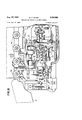
- FIG. 2 a plan view of the machine, with :a cover member removed and with certain parts shown in section and other parts broken away for clarity of illustration;
- FIG. 3 is end :elevational view of the machine a work supporting member brolcen away in part;
- FIG. 4 is a longitudinal, vertical section through the machine taken along a plane forwardly of that along which FIG. lis taken; 4 A
- FIG. 5 is an enlarged detail view, mainly in horizontal section, of a portion of the looper rod forming part of the through and through stitch forming mechanism;
- FIG. 6 is a side view of a small block forming part of the mechanism shown in FIG. 5
- FIG. 7 is an end view of saidblock
- FIG. 8 is a plan view of the left-hand portion of the machine, with )8 cover member removed and certain parts broken away;
- FIG. '9 is a vertical sectional view taken along the line 99o f FIG. 1;
- FIG. 10 is a plan view of the throat plate and the feed dogs embodied in the machine.
- FIG. 11 is an enlarged sectional view taken transversely through the machine and illustrates the trimmer operating mechanism and connections for imparting needle avoid movements to the four-motion looper;
- FIG. 12 is an enlarged sectional view taken transversely through the machine and shows the driving connections for rocking the needle carrying member
- FIG. 13 is a perspectiye'view showing the thread supply and the thread guides and take up means embodied in the machine.
- the machine comprises a main frame 10' which is relativ ely low and serves to support all of the mechanism of the machine and to enclose most of the driving connections for the operated parts.
- a removable top closure member 11 is secured to the frame lll by means of screws or the like, a gasket being provided between the frame and the cover member to form a lubricant-tighthousing.
- the frame construction is such that two lubricant containing compartments 13 and -14are provided, these preferablybein'g in communication through suitable openings (not shown) in a wall 10p of theframe.
- a main drive shaft which extends outwardly through the right end wall and has secured thereto, outside of the enclosed housing, a combined handwheel and pulley 16 by means of which power may be supplied to the machine.
- Shaft 15 extends outwardly through the left end wall of the enclosed housing and beneath a Work supporting member 17 which is pivotally mounted on the main frame for outward swinging movement to provide access to the parts beneath the work supporting surface.
- the illustrative machine is provided with work feeding mechanism which may suitably be of the character disclosed in said Wallenberg et a1.
- It comprises a main feed dog 18 and a differential feed dog 19 (FIGS. 2 and 10) these being carried respectively by feed bars 182; and 1% (FIG. 1).
- a chain feed dog'18b Connected with the main feed bar is a chain feed dog'18b (FIGS. 3 and 1 0).
- the feed bars are reciprocated longitudinally by means of pitmans 20 and 21 having strap portions surrounding eccentrics carried by the main drive shaft 15 adjacent its ,left end.
- the feed bars 18a and 19a are arranged to ride upon another eccentric on the shaft 15 adapted to impart lifting and lowering movements to the forward ends of the feed bars.
- Cooperating with the feed dogs 18, 18b and 19 is a presser foot 22 which may be mounted in the manner disclosed in said Wallenberg et aLpatent.
- the stitch forming devices include a pair of curved needles 23 and 24 (FIGS. 1, 2 and 3) carried by a rockable member or arm 25 secured to a rock shaft 26 (FIGS. 3 and 8) extending through the left end wall of the enclosed housing.
- the shaft 26 has secured thereto an arm 27 (FIGS. 1 and 12) the outer end of which is pivotally connected with the upper end of a pitman 28.
- the lower end of this pitman cooperates with a crank portion 29 of the main drive shaft 15.
- a finger 30 adapted to dip into the lubricant within the chamber 13 and create a spray or mist for the lubrication of various parts within the enclosed housing.
- a thread carrying looper 34 (FIG. 1) wihich is mounted for longitudinal reciprocation along a line inclined to the horizontal and in a vertical plane perpendicular to the direction of feed.
- This looper is carried by a rod 35 mounted for reciprocation in a bearing sleeve in the left end wall of the housing. At its inner end the rod 35 is connected by a link '36 with the upper end of an arm 37 mounted for rocking movement about a rod or shaft 38.
- an arm 39 carrying a ball pin at its outer end which cooperates with a pitman 40 the lower end of which cooperates with a spherical crank portion 41 of the shaft 15.
- a finger 42 arranged to dip into the lubricant within the chamber 13 and to disperse the same therein.
- Looper 34 passes through the loop of thread carried by the needle 23 and presents its own loop at the right side of the work sub stantially at the level of the work supporting surface of member 17.
- a thread carrying looper 43 or a spreader 43a is arranged to cooperate with looper 34. If the member 43 is a thread carrying looper, as shown in FIGS.
- the overedge stitch forming member is a spreader, as indicated at 43a in FIG. 13, it will carry the loop of thread from looper 34 and carry this into the path of the needle 23.
- the rod 44 is carried by a rod 44 arranged for longitudinal reciprocation and also for oscillation about its axis. This rod is journaled in a sleeve 45 (FIGS 1 and 8) having a helical slot 46 extending through the same.
- Rod 44 carries a helical key 47 arranged rto ride in the slot 46 so that as the rod 44 is reciprocated longitudinally it will also be oscillated about its axis.
- the latter is provided with spaced washers 48 between which are fitted forked cylindrical end portions 49 (FIG. 1) of an arm 51) mounted for rocking movement about a rod or shaft 51.
- an arm 52 Connected with the arm 50 is an arm 52 which extends toward the left and carries at its outer end a ball pin cooperating with a spherical strap at the upper end of a pitman 53. At its lower end this pitman cooperates with a spherical crank portion 54 0f the drive shaft 15.
- Suitable edge trimming mechanism is provided for trimming the free edges of superposed layers of work as they advance toward the stitching point in order to insure uniformity of the overedge stitching in relation to such edges.
- This trimming mechanism is arranged to operate upon the work in the region designated 56 in FIG. 10'.
- a stationary blade 57a (FIG. 2) is provided below the throat plate and extends upwardly to the top surface of the latter.
- Cooperating with this stationary blade is a movable blade 57 adjustably secured in a head 58 carried by a rock arm 59 (FIG.2).
- This rock arm is secured to a shaft 60 suitably journaled for rocking movement in the left end wall of the enclosed housing. At its inner end the shaft has secured thereto an arm.61 (see also FIG.
- a four-motion looper 64 Co operating with the needle 24 when the latter is passed downwardly through the throat plate is a four-motion looper 64 (FIG. 4).
- This looper is carried by an arm 65 secured to a looper rod 66 which is mounted for longitudinal sliding movement and limited oscillatory movement in suitable bearings provided in the main frame. Adjacent its right end the rod 6 6 is provided with spaced washers 67 which ane suitably retained on the red as by a collar 67a (FIG. 9) and which cooperate with cylindrical formations 68 at the lower end of a forked arm 69.
- the cylindrical portions 68 are disposed at opposite sides of the rod 66.
- Arm 69 is carried :by a rod or shaft 70 and has integrally connected with it, by means of a sleeve or the like, an arm 71 which extends toward the right. (See also FIGS. -1 and 2.)
- a ball pin mounted in the outer end of arm 71 cooperates With a spherical strap at the upper end of la pitman '72. Adjacent its. lower end this pitman has a spherical strap cooperating with a spherical eccentric 73 (see also FIG. 9) carried by the main drive shaft 15. It will be apparent that upon the rotation of shaft 15 the rod 66 will be shifted back and forth in an axial direction and will thereby impart loop seizing and shedding movements to the looper 64.
- a downwardly extending finger "74 carried by the pitman 72 is arranged to dip into the lubricant within the chamber 14 and disperse a mist for the lubrication of the parts within, this chamber.
- Needle avoid movements are imparted to the looper 64 by connections from the trimmer blade operating mechanism described above.
- a rock member 77 For this purpose there is mounted on the rod 66 between bearings 75 and 76' (FIG. 4) a rock member 77.
- This as best shown in FIG. 5, has a lateral extension '78 which provides a guide channel 79 in which rides ablock 80.
- the latter has a stem 81 fitted within a transverse opening through the rod 66 and clamped therein by meansof a small block 8-2.
- the left end of the rod 66 is hollow, as indicated at 66a, and thus provides access to a set screw 83- having screw threaded engagement with the rod 66 to permit tight clainping of the block 82 against the stem 81.
- the looper rod 66 will be oscillated toa limited extent so as to provide a needle avoid movement of the looper 64.
- the timing of the operation of the trimmer 'ismade such as to coincide with the desired needle avoid movement of the looper 64.
- the extent of such needlejavoid movement may be varied, within limits, to suit particular circumstances, such sioriing device 96 and then to a fixed guide member 97' carried by the frame of the machine. From the latter, thread N is passed through aligned openings in downwardly extending arms of a bracket 98- adjustably secured to the frame of the machine.
- a cam-shaped arm 99 secured to the needle carrying rock member engages the thread between the downwardly extending arms of bracket 98 to impart a pull off and take up action to the thread N.
- thread N is passed through posed arms of a bracket 102 adjustably secured to the as the diameter of needle24, and the like, by varying the 1 connection between 'the'arm34 and link 85'.
- arm 84 is provided with an elongated opening 88 with which'cooperates a idol-r87 providing the pivotal connection between the arm and link.
- the machine constructed in accordance with the invention is. adapted to produce an overedge line of stitching around the free edge of the layers of the work advanced past the stitching point and to provide, in addition, lines of through and through stitches of the 401 type inwardly a suitable dis- I tance from the free edge of the work.
- the overedge stitch may either be a two-thread or a three-thread stitch, depending upon whether the stitch forming member 43 is in the form of athread carrying overedge looper or is in the term of a spreader, as shown at 43a in FIG. .13.
- any suitable spacing of the needles Q3 and 24 may be provided, depending upon the work to be performed. They are spaced rearwa-rdly in relation to each other, as they pass through the throat plate, a distance of a tow stitch len-gths in order to provide clearance between them for the movement of the other stitch forming devicesdescribed. They are spaced laterally of the line of stitch formation to conform with the desired relative locations of'the two lines of stitching;
- the needle 23 is arranged to enter the fabric at A2 of an inch .f-rom the trimmed edge, while the needle 24 is arranged to pass through the fabric at a point of an inch inwardly of the line along which the needle- 23 enters the frame of the machine.
- Thread u passes through an opening in afixed guide 103, then down to .an adjustable guide 103a, in more or less direct. alignment with underlooper 34 to which the thread is then led.
- a rearwardly and upwardly extending .arm 104 carried by the rock member 25 serves to impart a pull oh and take up action to the thread it at the appropriate time inthe stitch-forming cycle, Thread "0' passes firom guide 97 through an eyelet in a laterally extending arm 106 of a bracket 1'05 adjustably mounted. on the frame, of the machine; Bracket 105 is positioned above the bracket 10-2 and'ha's twospaced arms straddling the arm 104 and through which the thread 0 is passed'from the eyelet in arm 106.
- looper thread L passes from guide 97 through an eye in-a laterally extending arm 108 of bracket 102. From here it passes through an eye in bracket 103 and then down 'to laterally spaced eyelets carried by a plate 109 beneath the work supporting surface of the machine. Plate 109 has an elongated opening through it between the spaced eyelets mentioned, and through this opening extends a cam 110 secured to the main drive shaftlS. Thiscam serves to impart the desired pull oil and take up action to the thread L.
- the needle 23 may enter the [Eabric along .a line F7 of an inch inwardly of the free edge. and the needle 24 may enter the fabric of an inch inwardly of the line along which the needle 23 renters I the fabric.
- a machine so constructed would be known machine is adapted to jproduce' a three-thread overedge stitch there will be five'threads altogether supplied from cones 90, 91, 92, 9'3 and 94 (-FIG. 13). These threads have been designated N, is, n, a and L to indicate, .respectively, the threads supplied to the overedge curved needle 23 the needle '24, the underlooper 34, the over edge looper 43 and the looper 64.
- All of the threads extend from their cones through guide openings in a rod extending across the top of each one of them to and through suitable guide openings in a bar 95. From here each thread passes between the discs of a thread tenabove it will be apparent that superposed layers of work may have their edges trimmed and then provided with an overedge line of stitching anda through and through line of stitching spaced inwardly a suitable distance from the. overedge stitching to provide a strong seam.
- the particular combination of means provided for this purpose is compact and capable of exceptionally high speed .operation.
- the provision of separate connections from the drive shaft for reciprocating the underlooper 34 and thelooper rod 66 enables each of these members to be drivenonly the necessary amount for proper sea-m formation.
- a main rotary drive shaft extending longitudinally of said housing and having one end within said extension beneath said work supporting surface, the opposite end of said shaft extending outwardly of said housing and carrying a handwheel and pulley for turning the same
- stitch forming devices including a rockable member extending through a wall of said housing and having an arm carrying a plurality of curved needles, complementary stitch forming devices cooperate.
- a looper rod parallel with said drive shaft disposed mainly within said housing but extending outwardly therefrom beneath said work supporting surface and I having rigidly connected therewith a four motion looper arranged to cooperate with another of said needles to form a line of through and through two-thread chain stitches spaced from said overedge line of stitches, oscillatable means Within said housing cooperating with said looper rod to oscillate the latter about its axis, said rod being reciprocable longitudinally relative tosaid oscillatable means to imp-ant loop seizing and shedding movements to said looper and being oscillatable about its axis by said osoillatable means to impart needle avoid movements to said looper, and connections from said drive shaft within said housing for rocking said rockab-le member, for operating said complementary stitch forming devices, for imparting said longitudinal movementsto said looper rod and for oscillating said .oscillatable means and said rod, all in coordinated relation to form said lines of stitches.
- means for trimming the edge of work to be stitched in advance of the point of stitch formation comprising a rockable arm, and partially common connections from said drive shaft to said arm for rocking the latter and .to said oscillatable means for oscillating the same.
- said complementary stitch forming devices comprising ya reciprocatory thread carrying member and a cooperating reciprocatory and oscillatory member, said members and said looper rod being all mounted for reciprocation in parallel vertical planes.
- means for supplying and guiding threads to the several thread carrying stitch forming devices means for supplying and guiding threads to the several thread carrying stitch forming devices, said means directing all but one of said threads along a path in the region of said rochable member, means carried by said rockable member for engaging said all but one of saidthreads to impart a take-up action thereto, and cam means on said drive shflt arranged to impart a take-up action to said one thread 5.
- said rockable member having a'plurality of arms connected therewith, tone of said arms being arranged to engage and provide a take-up action to the threads extending to said needles and the other of said arms being arranged to engage and impart a take-up action to the threads extending to said complementary stitch forming devices.
- connections from said drive shaft for operating said rockable member and said complementary stitch forming devices being provided in one portion of said housing, and the connections from said drive shaft for reciprocating said looper rod being provided in another portion of said housing which is further to the right of said Work supporting extension than said one portion of-said housirig.
- connections from said drive shaft foropcrating said rockable member, said rockable arm and said complementary stitch forming devices being provided in one portion of said housing, and the connections from said drive shaft for reciprocating said looper rod being provided in another portion of said housing which is further to the right of said'work supporting extension than :said one portion of said housing.
- stitch forming devices including a rockable member extending through awall of said housing and carrying a curved needle with a thread carrying eye adapted to be moved from a position above said surface to a point below the same, a reciprocatory thread carrying looper, a rod having said looper secured thereto extending through a wall of said housing and arranged for reciprocation transverse to the direction of seam formation to cause said looper to cooperate with said needle beneath said work support and carry its own thread to a point at one side of the line of seam formation, a cooperating stitch forming member extending through said last-mentioned wall of operating said rockable member, said looper and said cooperating member in coordination to produce an overedge stitch, an extra curved needle
- connections from said drive shaft for operating said first-mentioned looper, said cooperating stitch forming member and said four motion looper being disposed atone side of the line of seam formation within said lubricant retaining housing.
Landscapes
- Engineering & Computer Science (AREA)
- Textile Engineering (AREA)
- Sewing Machines And Sewing (AREA)
Description
Aug. 27, 1963 R. A. HAYES MACHINE FOR PRODUCING SAFETY STITCH 8 Sheets-Sheet 1 Filed Jan. 19, 1959 Aug. 27, 1963 Filed Jan. 19, 1959 FIG. 2
R. A. HAYES MACHINE FOR PRODUCING SAFETY STITCH 8 Sheets-Sheet 2 Aug. 27, 1963 R. A. HAYES 3, 0
MACHINE FOR PRODUCING SAFETY STITCH Filed Jan. 19, 1959 8 Sheets-Sheet 3 FIG. 3
1963 R. A. HAYES 3,101,686
MACHINE FOR PRODUCING SAFETY STITCH Filed Jan. 19, 1959 8 Sheets-Sheet 4 Aug. 27, 1963 R. A. HAYES MACHINE FOR PRODUCING SAFETY STITCH 8 Sheets-Sheet 5 Filed Jan. 19, 1959 Aug. 27, 1963 R. A. HAYES 3,101,586
MACHINE FOR PRODUCING SAFETY STITCH Filed Jan. 19, 1959 8 Sheets-Sheet e 03 g N m m m I E 1 L; L i I 1. \IHII\ 3 \VV 1 Q Q IH HE Q MllllkllIIQIIHIIIIHIIII H1! u. Hw-
I .0 ---m g 5 w- +Ll 7,1963 R. A. HAYES 3,101,686
MACHINE FOR PRODUCING SAFETY STITCH Filed Jan. 19, 1959 8 Sheets-Sheet 7 Aug. 27, 1963 R. A. HAYES MACHINE FOR PRODUCING SAFETY STITCH 8 Sheets-Sheet 8 Filed Jan. 19, 1959 United States Patent MACHINE FOR PRODUCING SAFETY STITCH Robert A. Hayes, Franklin Park, Ill, assignor to Union Special Machine Company, Chicago, lll.,' incorporation of Illinois Filed Jan. 19, 1959, Ser. No. 787,424 12 Claims. (Cl. 112-462) This invention relates to an improved machine for producing a so-called safety stitch which involves at least one line of through and through stitching spaced from the edge of two superposed layers of fabric and a line of overedge stitching extending over the edge of said layers of fabric.
3,101,686 Patented A 27, 1963 There is -so incorporated in the machine simple and I readily accessible means for controlling the various threads An object of the invention has been to provide a simple and reliable mechanism for producing a seam of the character indicated in a machine adapted for high speed operation. Toward this end the invention has been applied to a modern machine of the character particularly constructed for the high speed production of an overedge line of stitching. To such a machine there has been added special mechanism for producing at least one line of through and through stitches spaced inwardly of the free edges of the superposed layers of fabric a desired distance. A
A feature of the invention comprises the incorporation in a machine of the character indicated of means for providing a through and through line of two-thread chain stitches which involves a reciprocatory or oscillatory needle and a looper which is reciprooated across the line of feed for loop seizing and shedding purposes andis oscillated to a slight extent for needle avoid purposes. The looper mechanism and its operating means for this purpose is so positioned in an existing style of machine for producing overedge stitches as not to intQ T fi'e require relocation of any of the parts of the latter.
Considering the machine as a whole there is provided a plurality of curved needles carried by an oscillatory arrn and a plurality of reciprocatory looper carrying rods, one arranged to cooper-ate with one of the needles to produce a line of through and through stitches of the character mentioned and two arranged to cooperate with another of said needles to produce the overedge line of sn'tching. Several of the looper carrying rods mentioned are also oscillated about axes to cooperate with the related needle to produce the desired lines of stitching. This arrangement issuch that simple movements are imparted to each of the stitch forming elements and simple connections are provided from the main drive shaft for imparting the various necessary movements. As a result of the combination as a whole there is provided a mechanism for forming a safety stitch which is capable of very high speed operation. A minimum number of moving parts is required and these are subjected to very simple movements which may be imparted at high speeds.
A special feature of the invention is the provision of simple connections from other mechanism required in the machine, such as an edge trimming mechanism, for oscillating the looper rod which takes part in the formation of the through and through line of stitching to provide the needle avoid movements to the related looper. This results in a simplification of the operating connections and enables the incorporation of the entire mechanism in the frame structure of a machine originally capable of producing only an overedge line of stitching.
As a further feature of the invention, all of the mechanisrns for operating the looper carrying rods are in an enclosed housing provided with means for insuring adequate lubrication of these mechanisms. To facilitate the incorporation of this feature, all of the operating mechanism for the several looper rods is located toward the right of the stitch forming zone of the machine.
supplied to the several needles and their cooperating loopers. This means comprises a pair of take up arms mounted on the needle carrying arm or member and so arranged in relation to fixed guides as to effect a take up [action on all the threads, except that supplied to the looper which enters into the formation of the through and through line of stitching. A special cam member'on the main drive shaft in the region of the needle carrying arm serves to impart the desired take up action to that looper mead- Other objects, features and advantages of the invention will appear irolm the following detailed description of an illustrative embodiment of the same which Will now be given in conjunction with the accompanying drawings, in which:
FIG. 1 is a longitudinal, vertical section through a machine embodying the inve'ntion;
FIG. 2 a plan view of the machine, with :a cover member removed and with certain parts shown in section and other parts broken away for clarity of illustration;
FIG. 3 is end :elevational view of the machine a work supporting member brolcen away in part;
FIG. 4 is a longitudinal, vertical section through the machine taken along a plane forwardly of that along which FIG. lis taken; 4 A
FIG. 5 is an enlarged detail view, mainly in horizontal section, of a portion of the looper rod forming part of the through and through stitch forming mechanism;
FIG. 6 is a side view of a small block forming part of the mechanism shown in FIG. 5
FIG. 7 is an end view of saidblock;
FIG. 8 is a plan view of the left-hand portion of the machine, with )8 cover member removed and certain parts broken away;
FIG. '9 is a vertical sectional view taken along the line 99o f FIG. 1;
FIG. 10 is a plan view of the throat plate and the feed dogs embodied in the machine;
FIG. 11 is an enlarged sectional view taken transversely through the machine and illustrates the trimmer operating mechanism and connections for imparting needle avoid movements to the four-motion looper;
FIG. 12 is an enlarged sectional view taken transversely through the machine and shows the driving connections for rocking the needle carrying member; and
FIG. 13 is a perspectiye'view showing the thread supply and the thread guides and take up means embodied in the machine.
Referring now to the drawings, the invention has been illustrated as applied to a high speed overedge stitching machine of the character disclosed in the Wallenberg et al. US. Patent No. 2,704,042, granted March '15, 1955. Reference may be had to said patent for a disclosure of certain details of the machine which are not shown herein. I
The machine comprises a main frame 10' which is relativ ely low and serves to support all of the mechanism of the machine and to enclose most of the driving connections for the operated parts. A removable top closure member 11 is secured to the frame lll by means of screws or the like, a gasket being provided between the frame and the cover member to form a lubricant-tighthousing. To the bottom of the frame 10 there is similarly secured a bottom plate 12. The frame construction is such that two lubricant containing compartments 13 and -14are provided, these preferablybein'g in communication through suitable openings (not shown) in a wall 10p of theframe. Journaled in suitable bearings provided-in the end walls of the enclosed housing and in the wall 10d and another intermediate wall 1% is a main drive shaft which extends outwardly through the right end wall and has secured thereto, outside of the enclosed housing, a combined handwheel and pulley 16 by means of which power may be supplied to the machine. Shaft 15 extends outwardly through the left end wall of the enclosed housing and beneath a Work supporting member 17 which is pivotally mounted on the main frame for outward swinging movement to provide access to the parts beneath the work supporting surface.
The illustrative machine is provided with work feeding mechanism which may suitably be of the character disclosed in said Wallenberg et a1. patent. It comprises a main feed dog 18 and a differential feed dog 19 (FIGS. 2 and 10) these being carried respectively by feed bars 182; and 1% (FIG. 1). Connected with the main feed bar is a chain feed dog'18b (FIGS. 3 and 1 0). The feed bars are reciprocated longitudinally by means of pitmans 20 and 21 having strap portions surrounding eccentrics carried by the main drive shaft 15 adjacent its ,left end. The feed bars 18a and 19a are arranged to ride upon another eccentric on the shaft 15 adapted to impart lifting and lowering movements to the forward ends of the feed bars. Cooperating with the feed dogs 18, 18b and 19 is a presser foot 22 which may be mounted in the manner disclosed in said Wallenberg et aLpatent.
The stitch forming devices include a pair of curved needles 23 and 24 (FIGS. 1, 2 and 3) carried by a rockable member or arm 25 secured to a rock shaft 26 (FIGS. 3 and 8) extending through the left end wall of the enclosed housing. Within the housing the shaft 26 has secured thereto an arm 27 (FIGS. 1 and 12) the outer end of which is pivotally connected with the upper end of a pitman 28. The lower end of this pitman cooperates with a crank portion 29 of the main drive shaft 15. At the lower end of pitman 2.8 there is provided a finger 30 adapted to dip into the lubricant within the chamber 13 and create a spray or mist for the lubrication of various parts within the enclosed housing.
As the needle carrying arm 25 is rocked through the connections described, the thread carrying ends of the two needles will be passed downwardly through openings 31 and 32 in a throat plate 33 (FIG. 10). Cooperating with the needle 2-3 to form overedge stitches around the edge of the work being fed along the throat plate 33 is a thread carrying looper 34 (FIG. 1) wihich is mounted for longitudinal reciprocation along a line inclined to the horizontal and in a vertical plane perpendicular to the direction of feed. This looper is carried by a rod 35 mounted for reciprocation in a bearing sleeve in the left end wall of the housing. At its inner end the rod 35 is connected by a link '36 with the upper end of an arm 37 mounted for rocking movement about a rod or shaft 38. Connected with the arm 37 and extending to the right therefrom is an arm 39 carrying a ball pin at its outer end which cooperates with a pitman 40 the lower end of which cooperates with a spherical crank portion 41 of the shaft 15. To the lower end of pitman 40 is secured a finger 42 arranged to dip into the lubricant within the chamber 13 and to disperse the same therein. Looper 34 passes through the loop of thread carried by the needle 23 and presents its own loop at the right side of the work sub stantially at the level of the work supporting surface of member 17. Here either a thread carrying looper 43 or a spreader 43a is arranged to cooperate with looper 34. If the member 43 is a thread carrying looper, as shown in FIGS. 1 and 13, it serves to pass its thread through the loop of thread carried by looper 34 and presents its own loop in the path of the needle 23 above the work supporting surface at the time this needle is again rocked downwardly. If the overedge stitch forming member is a spreader, as indicated at 43a in FIG. 13, it will carry the loop of thread from looper 34 and carry this into the path of the needle 23. To impart the desired motion to the looper '43, or spreader 43a, the latter is carried by a rod 44 arranged for longitudinal reciprocation and also for oscillation about its axis. This rod is journaled in a sleeve 45 (FIGS 1 and 8) having a helical slot 46 extending through the same. Rod 44 carries a helical key 47 arranged rto ride in the slot 46 so that as the rod 44 is reciprocated longitudinally it will also be oscillated about its axis. For reciprocating the rod 44 the latter is provided with spaced washers 48 between which are fitted forked cylindrical end portions 49 (FIG. 1) of an arm 51) mounted for rocking movement about a rod or shaft 51. Connected with the arm 50 is an arm 52 which extends toward the left and carries at its outer end a ball pin cooperating with a spherical strap at the upper end of a pitman 53. At its lower end this pitman cooperates with a spherical crank portion 54 0f the drive shaft 15. It will thus be seen that upon rotation of the shaft 15 the rod 44 will be shifted longitudinally, and by virtue of the key and slot arrangement described it will also be oscillated. Pitman 53 at its lower end is provided with a finger 55 arranged to dip into the lubricant supply in the chamber 13 and assist in dispersing the latter in the form of a mist.
Suitable edge trimming mechanism is provided for trimming the free edges of superposed layers of work as they advance toward the stitching point in order to insure uniformity of the overedge stitching in relation to such edges. This trimming mechanism is arranged to operate upon the work in the region designated 56 in FIG. 10'. A stationary blade 57a (FIG. 2) is provided below the throat plate and extends upwardly to the top surface of the latter. Cooperating with this stationary blade is a movable blade 57 adjustably secured in a head 58 carried by a rock arm 59 (FIG.2). This rock arm is secured to a shaft 60 suitably journaled for rocking movement in the left end wall of the enclosed housing. At its inner end the shaft has secured thereto an arm.61 (see also FIG. 11) to the lower end of which is pivotally connected a pitman 62 the opposite end of which cooperates with a crank portion 63 of the shaft 15. Upon turning of this drive shaft the arm 61 and shaft 60 will be rocked back and forth thus causing the movable trimmer blade carrying arm to be rocked downwardly and upwardly.
Co operating with the needle 24 when the latter is passed downwardly through the throat plate is a four-motion looper 64 (FIG. 4). This looper is carried by an arm 65 secured to a looper rod 66 which is mounted for longitudinal sliding movement and limited oscillatory movement in suitable bearings provided in the main frame. Adjacent its right end the rod 6 6 is provided with spaced washers 67 which ane suitably retained on the red as by a collar 67a (FIG. 9) and which cooperate with cylindrical formations 68 at the lower end of a forked arm 69. The cylindrical portions 68 are disposed at opposite sides of the rod 66. Arm 69 is carried :by a rod or shaft 70 and has integrally connected with it, by means of a sleeve or the like, an arm 71 which extends toward the right. (See also FIGS. -1 and 2.) A ball pin mounted in the outer end of arm 71 cooperates With a spherical strap at the upper end of la pitman '72. Adjacent its. lower end this pitman has a spherical strap cooperating with a spherical eccentric 73 (see also FIG. 9) carried by the main drive shaft 15. It will be apparent that upon the rotation of shaft 15 the rod 66 will be shifted back and forth in an axial direction and will thereby impart loop seizing and shedding movements to the looper 64. A downwardly extending finger "74 carried by the pitman 72 is arranged to dip into the lubricant within the chamber 14 and disperse a mist for the lubrication of the parts within, this chamber.
Needle avoid movements are imparted to the looper 64 by connections from the trimmer blade operating mechanism described above. For this purpose there is mounted on the rod 66 between bearings 75 and 76' (FIG. 4) a rock member 77. This, as best shown in FIG. 5, has a lateral extension '78 which provides a guide channel 79 in which rides ablock 80. The latter has a stem 81 fitted within a transverse opening through the rod 66 and clamped therein by meansof a small block 8-2. The left end of the rod 66 is hollow, as indicated at 66a, and thus provides access to a set screw 83- having screw threaded engagement with the rod 66 to permit tight clainping of the block 82 against the stem 81. It will be 'understo-o-d that the arrangement is such that the rod 66is tree to slide axially within themember 77 but will turn with the latter. Turning of sleeve member 77 is brought about through a downwardly extending arm 84 integral therewith having its lower end pivotally connected with a link 85 (FIG. i l). The opposite end of this link is connected by a screw stud 8'6 with the arm 61 through i which the movable trimmer blade carrying arm is rocked.
Thus, as the trimmer blade is operated, the looper rod 66 will be oscillated toa limited extent so as to provide a needle avoid movement of the looper 64. The timing of the operation of the trimmer 'ismade such as to coincide with the desired needle avoid movement of the looper 64. The extent of such needlejavoid movement may be varied, within limits, to suit particular circumstances, such sioriing device 96 and then to a fixed guide member 97' carried by the frame of the machine. From the latter, thread N is passed through aligned openings in downwardly extending arms of a bracket 98- adjustably secured to the frame of the machine. A cam-shaped arm 99 secured to the needle carrying rock member engages the thread between the downwardly extending arms of bracket 98 to impart a pull off and take up action to the thread N. From bracket 98 thread N is passed through posed arms of a bracket 102 adjustably secured to the as the diameter of needle24, and the like, by varying the 1 connection between 'the'arm34 and link 85'. For this purpose arm 84 is provided with an elongated opening 88 with which'cooperates a idol-r87 providing the pivotal connection between the arm and link. i
It will be seen from thetoregoing' that the machine constructed in accordance with the invention is. adapted to produce an overedge line of stitching around the free edge of the layers of the work advanced past the stitching point and to provide, in addition, lines of through and through stitches of the 401 type inwardly a suitable dis- I tance from the free edge of the work. The overedge stitch may either be a two-thread or a three-thread stitch, depending upon whether the stitch forming member 43 is in the form of athread carrying overedge looper or is in the term of a spreader, as shown at 43a in FIG. .13.
When the later is used it serves to pick up the thread from the underlooper 34 and to carry this upwardly and across the top of the work into the pathof the needle 23.
Any suitable spacing of the needles Q3 and 24 may be provided, depending upon the work to be performed. They are spaced rearwa-rdly in relation to each other, as they pass through the throat plate, a distance of a tow stitch len-gths in order to provide clearance between them for the movement of the other stitch forming devicesdescribed. They are spaced laterally of the line of stitch formation to conform with the desired relative locations of'the two lines of stitching; In a typical example the needle 23 is arranged to enter the fabric at A2 of an inch .f-rom the trimmed edge, while the needle 24 is arranged to pass through the fabric at a point of an inch inwardly of the line along which the needle- 23 enters the frame of the machine. From here thread u passes through an opening in afixed guide 103, then down to .an adjustable guide 103a, in more or less direct. alignment with underlooper 34 to which the thread is then led. A rearwardly and upwardly extending .arm 104 carried by the rock member 25 serves to impart a pull oh and take up action to the thread it at the appropriate time inthe stitch-forming cycle, Thread "0' passes firom guide 97 through an eyelet in a laterally extending arm 106 of a bracket 1'05 adjustably mounted. on the frame, of the machine; Bracket 105 is positioned above the bracket 10-2 and'ha's twospaced arms straddling the arm 104 and through which the thread 0 is passed'from the eyelet in arm 106. From here the thread 0 is passed forwardly and then downwardly through a guide tube 107 to a point adjacentth'e loveredge looper 43 to which it led. It will beseen that arm '104 serves to. impart a pull off and take up action to the thread 0' in a manner similarto its action applied to thread u. Looper thread L passes from guide 97 through an eye in-a laterally extending arm 108 of bracket 102. From here it passes through an eye in bracket 103 and then down 'to laterally spaced eyelets carried by a plate 109 beneath the work supporting surface of the machine. Plate 109 has an elongated opening through it between the spaced eyelets mentioned, and through this opening extends a cam 110 secured to the main drive shaftlS. Thiscam serves to impart the desired pull oil and take up action to the thread L.
-- Through the coaction of the variousde'vices described fabric, This is known as a 5 gauge-% macln'ne. in
another typical example the needle 23 may enter the [Eabric along .a line F7 of an inch inwardly of the free edge. and the needle 24 may enter the fabric of an inch inwardly of the line along which the needle 23 renters I the fabric. A machine so constructed would be known machine is adapted to jproduce' a three-thread overedge stitch there will be five'threads altogether supplied from cones 90, 91, 92, 9'3 and 94 (-FIG. 13). These threads have been designated N, is, n, a and L to indicate, .respectively, the threads supplied to the overedge curved needle 23 the needle '24, the underlooper 34, the over edge looper 43 and the looper 64. All of the threads extend from their cones through guide openings in a rod extending across the top of each one of them to and through suitable guide openings in a bar 95. From here each thread passes between the discs of a thread tenabove it will be apparent that superposed layers of work may have their edges trimmed and then provided with an overedge line of stitching anda through and through line of stitching spaced inwardly a suitable distance from the. overedge stitching to provide a strong seam. The particular combination of means provided for this purpose is compact and capable of exceptionally high speed .operation. The provision of separate connections from the drive shaft for reciprocating the underlooper 34 and thelooper rod 66 enables each of these members to be drivenonly the necessary amount for proper sea-m formation. It has been found that the extent of reciprocation required forthe looper 64- is less than that required for looper 34. .Thus, in a typical machine embodying the invention, the looper 34 has been given a stroke of 1 inch whereas the looper 64, and hence itsrod 66, has required only a "V3 inch stroke.
While a preferred embodiment of the invention has been disclosed in some detail, it will be understood that various modifications of certain of the mechanisms disclosed may be employed within the scope of the invention defined by the appended claims.
from said housing at one end thereof and providing a Work supporting surf-ace at its top, a main rotary drive shaft extending longitudinally of said housing and having one end within said extension beneath said work supporting surface, the opposite end of said shaft extending outwardly of said housing and carrying a handwheel and pulley for turning the same, stitch forming devices including a rockable member extending through a wall of said housing and having an arm carrying a plurality of curved needles, complementary stitch forming devices cooperate. ing with one of said needles to form a line of overedge stitches, a looper rod parallel with said drive shaft disposed mainly within said housing but extending outwardly therefrom beneath said work supporting surface and I having rigidly connected therewith a four motion looper arranged to cooperate with another of said needles to form a line of through and through two-thread chain stitches spaced from said overedge line of stitches, oscillatable means Within said housing cooperating with said looper rod to oscillate the latter about its axis, said rod being reciprocable longitudinally relative tosaid oscillatable means to imp-ant loop seizing and shedding movements to said looper and being oscillatable about its axis by said osoillatable means to impart needle avoid movements to said looper, and connections from said drive shaft within said housing for rocking said rockab-le member, for operating said complementary stitch forming devices, for imparting said longitudinal movementsto said looper rod and for oscillating said .oscillatable means and said rod, all in coordinated relation to form said lines of stitches.-
2. In asewing machine of the character set forth in claim 1, means for trimming the edge of work to be stitched in advance of the point of stitch formation, said means comprising a rockable arm, and partially common connections from said drive shaft to said arm for rocking the latter and .to said oscillatable means for oscillating the same. a
3. In a sewing machine of the character set forthin claim 1, said complementary stitch forming devices comprising ya reciprocatory thread carrying member and a cooperating reciprocatory and oscillatory member, said members and said looper rod being all mounted for reciprocation in parallel vertical planes.
4. In a sewing machine of the character set forth in claim 1, means for supplying and guiding threads to the several thread carrying stitch forming devices, said means directing all but one of said threads along a path in the region of said rochable member, means carried by said rockable member for engaging said all but one of saidthreads to impart a take-up action thereto, and cam means on said drive shflt arranged to impart a take-up action to said one thread 5. In a sewing machine of the character set forth in clairn 1, meansfor supplying and guiding a thread to each of said stitch forming devices, said means directing thread to said needles and to said complementary stitch forming devices along paths in the region of said rockable member, andmeans carried by said rockable member for engaging said threads to impart a take-up action thereto.
6. In a sewing machine of the character set forth in claim 5, said rockable member having a'plurality of arms connected therewith, tone of said arms being arranged to engage and provide a take-up action to the threads extending to said needles and the other of said arms being arranged to engage and impart a take-up action to the threads extending to said complementary stitch forming devices.
7. In a sewing machine of the character set forth in claim 1, said connections from said drive shaft for operating said rockable member and said complementary stitch forming devices being provided in one portion of said housing, and the connections from said drive shaft for reciprocating said looper rod being provided in another portion of said housing which is further to the right of said Work supporting extension than said one portion of-said housirig.
8. In a sewing machine of the character set forth in claim 2, said connections from said drive shaft foropcrating said rockable member, said rockable arm and said complementary stitch forming devices being provided in one portion of said housing, and the connections from said drive shaft for reciprocating said looper rod being provided in another portion of said housing which is further to the right of said'work supporting extension than :said one portion of said housing.
9. In a sewing machine adapted to produce a safety stitch and having a frame with a relatively low lubricant retaining main housing, a work supporting extension projecting from said housing at one end thereof and providing a work supporting surface at its top, a main rotary drive shaft extending longitudinally of said extension and beneath the work supporting surface thereof, stitch forming devices including a rockable member extending through awall of said housing and carrying a curved needle with a thread carrying eye adapted to be moved from a position above said surface to a point below the same, a reciprocatory thread carrying looper, a rod having said looper secured thereto extending through a wall of said housing and arranged for reciprocation transverse to the direction of seam formation to cause said looper to cooperate with said needle beneath said work support and carry its own thread to a point at one side of the line of seam formation, a cooperating stitch forming member extending through said last-mentioned wall of operating said rockable member, said looper and said cooperating member in coordination to produce an overedge stitch, an extra curved needle carried by said rockable member, a four motion looper cooperating with said extra needle, and connections within said housing from said drive shaft wholly independent of said first-mew tioned connections for imparting four motion movements to said four motion looper to form a two-thread chain stitch in conjunction with said extra needle.
10. In a sewing machine of the character set forth in claim 9, said connections from said drive shaft for operating said first-mentioned looper, said cooperating stitch forming member and said four motion looper being disposed atone side of the line of seam formation within said lubricant retaining housing.
11. In a sewing machine of the character set forth in claim 10, said first-mentioned looper, said cooperating stitch forming member and said four motion looper bping reciprocated along axes disposed in parallel vertical p anes.
12. In a sewing machine of the character set forth in claim 11, said first-mentioned looper being reciprocated to a greater extent than said four motion looper in a direction normal to the line of scam formation References (Iited in the'file of this patent UNITED STATES PATENTS
Claims (1)
1. IN A SEWING MACHINE ADAPTED TO PRODUCE A SAFETY STITCH AND HAVING A FRAME WITH A LOW LUBRICANT RETAINING MAIN HOUSING, A WORK SUPPORTING EXTENSION PROJECTING FROM SAID HOUSING AT ONE END THEREOF AND PROVIDING A WORK SUPPORTING SURFACE AT ITS TOP, A MAIN ROTARY DRIVE SHAFT EXTENDING LONGITUDINALLY OF SAID HOUSING AND HAVING ONE END WITHIN SAID EXTENSION BENEATH SAID WORK SUPPORTING SURFACE, THE OPPOSITE END OF SAID SHAFT EXTENDING OUTWARDLY OF SAID HOUSING AND CARRYING A HANDWHEEL AND PULLEY FOR TURNINJG THE SAME, STITCH FORMING DEVICES INCLUDING A ROCKABLE MEMBER EXTENDING THROUGH A WALL OF SAID HOUSING AND HAVING AN ARM CARRYING A PLURALITY OF CURVED NEEDLES, COMPLEMENTARY STITCH FORMING DEVICES COOPERATING WITH ONE OF SAID NEEDLES TO FORM A LINE OF OVEREDGE STITCHES, A LOOPER ROD PARALLEL WITH SAID DRIVE SHAFT DISPOSED MAINLY WITHIN SAID HOUSING BUT EXTENDING OUTWARDLY THEREFROM BENEATH SAID WORK SUPPORTING SURFACE AND HAVING RIGIDLY CONNECTED THEREWITH A FOUR MOTION LOOPER ARRANGED TO COOPERATE WITH ANOTHER OF SAID NEEDLES TO FORM A LINE OF THROUGH AND THROUGH TWO-THREAD CHAIN STITCHES SPACED FROM SAID OVEREDGE LINE OF STITCHES, OSCILLATABLE MEANS WITHIN SAID HOUSING COOPERATING WITH SAID LOOPER ROD TO OSCILLATE THE LATTER ABOUT ITS AXIS, SAID ROD BEING RECIPROCABLE LONGITUDINALLY RELATIVE TO SAID OSCILLATABLE MEANS TO IMPART LOOP SEIZING AND SHEDDING MOVEMENTS TO SAID LOOPER AND BEING OSCILLATABLE ABOUT ITS AXIS BY SAID OSCILLATABLE MEANS TO IMPART NEEDLE AVOID MOVEMENTS TO SAID LOOPER, AND CONNECTIONS FROM SAID DRIVE SHAFT WITHIN SAID HOUSING FOR ROCKING SAID ROCKABLE MEMBER, FOR OPERATING SAID COMPLEMENTARY STITCH FORMING DEVICES, FOR IMPARTING SAID LONGITUDINAL MOVEMENTS TO SAID LOOPER ROD AND FOR OSCILLATING SAID OSCILLATABLE MEANS AND SAID ROD, ALL IN COORDINATED RELATION TO FORM SAID LINES OF STITCHES.
Priority Applications (1)
| Application Number | Priority Date | Filing Date | Title |
|---|---|---|---|
| US787424A US3101686A (en) | 1959-01-19 | 1959-01-19 | Machine for producing safety stitch |
Applications Claiming Priority (1)
| Application Number | Priority Date | Filing Date | Title |
|---|---|---|---|
| US787424A US3101686A (en) | 1959-01-19 | 1959-01-19 | Machine for producing safety stitch |
Publications (1)
| Publication Number | Publication Date |
|---|---|
| US3101686A true US3101686A (en) | 1963-08-27 |
Family
ID=25141437
Family Applications (1)
| Application Number | Title | Priority Date | Filing Date |
|---|---|---|---|
| US787424A Expired - Lifetime US3101686A (en) | 1959-01-19 | 1959-01-19 | Machine for producing safety stitch |
Country Status (1)
| Country | Link |
|---|---|
| US (1) | US3101686A (en) |
Cited By (2)
| Publication number | Priority date | Publication date | Assignee | Title |
|---|---|---|---|---|
| US3398709A (en) * | 1964-01-31 | 1968-08-27 | Alphonse De Koninck | Machine for overcast sewing |
| US3881434A (en) * | 1973-04-26 | 1975-05-06 | Merrow Machine Co | Overedge sewing machine construction |
Citations (8)
| Publication number | Priority date | Publication date | Assignee | Title |
|---|---|---|---|---|
| US1528499A (en) * | 1920-11-04 | 1925-03-03 | Union Special Machine Co | Pocket-stitching machine |
| US1587957A (en) * | 1920-04-09 | 1926-06-08 | Huber Gustav | Machine for sewing together and covering the edges of knitted or woven fabrics |
| US1949073A (en) * | 1933-05-12 | 1934-02-27 | Horace F Gruman | Sewing machine |
| US2157373A (en) * | 1936-12-29 | 1939-05-09 | Willcox & Gibbs Sewing Machine | Thread handling device for sewing machines |
| US2704042A (en) * | 1950-11-17 | 1955-03-15 | Union Special Machine Co | Overedge sewing machine |
| US2730060A (en) * | 1952-11-28 | 1956-01-10 | Union Special Machine Co | Thread control mechanism for sewing machines |
| FR1116226A (en) * | 1954-06-02 | 1956-05-04 | Union Special Machine Co | Sewing machine, sewing process and resulting seams |
| US2834309A (en) * | 1954-08-05 | 1958-05-13 | Willcox & Gibbs Sewing Machine | Overedge sewing machine for making safety seam |
-
1959
- 1959-01-19 US US787424A patent/US3101686A/en not_active Expired - Lifetime
Patent Citations (8)
| Publication number | Priority date | Publication date | Assignee | Title |
|---|---|---|---|---|
| US1587957A (en) * | 1920-04-09 | 1926-06-08 | Huber Gustav | Machine for sewing together and covering the edges of knitted or woven fabrics |
| US1528499A (en) * | 1920-11-04 | 1925-03-03 | Union Special Machine Co | Pocket-stitching machine |
| US1949073A (en) * | 1933-05-12 | 1934-02-27 | Horace F Gruman | Sewing machine |
| US2157373A (en) * | 1936-12-29 | 1939-05-09 | Willcox & Gibbs Sewing Machine | Thread handling device for sewing machines |
| US2704042A (en) * | 1950-11-17 | 1955-03-15 | Union Special Machine Co | Overedge sewing machine |
| US2730060A (en) * | 1952-11-28 | 1956-01-10 | Union Special Machine Co | Thread control mechanism for sewing machines |
| FR1116226A (en) * | 1954-06-02 | 1956-05-04 | Union Special Machine Co | Sewing machine, sewing process and resulting seams |
| US2834309A (en) * | 1954-08-05 | 1958-05-13 | Willcox & Gibbs Sewing Machine | Overedge sewing machine for making safety seam |
Cited By (2)
| Publication number | Priority date | Publication date | Assignee | Title |
|---|---|---|---|---|
| US3398709A (en) * | 1964-01-31 | 1968-08-27 | Alphonse De Koninck | Machine for overcast sewing |
| US3881434A (en) * | 1973-04-26 | 1975-05-06 | Merrow Machine Co | Overedge sewing machine construction |
Similar Documents
| Publication | Publication Date | Title |
|---|---|---|
| US2704042A (en) | Overedge sewing machine | |
| US3776157A (en) | Flat stitch forming and cover thread laying mechanisms for sewing machines | |
| US2439332A (en) | Looper-actuating mechanism for sewing machines | |
| US2884883A (en) | Four motion looper for sewing machines | |
| US3688711A (en) | Machines stitch forming and thread controlling mechanisms for sewing | |
| US3101686A (en) | Machine for producing safety stitch | |
| US2729176A (en) | Feed-off-the-arm knit goods machine | |
| US3116706A (en) | Attachment for overedging | |
| US2152766A (en) | Sewing mechanism | |
| US2312858A (en) | Chain-stitch sewing machine | |
| US1996040A (en) | Sewing machine | |
| US2029242A (en) | Chain stitch sewing machine | |
| US3068818A (en) | Two-thread chainstitch sewing machine | |
| US2161140A (en) | Sewing machine | |
| US1950336A (en) | Sewing machine | |
| US2224028A (en) | Looper-mechanism for sewing machines | |
| US2718859A (en) | Looper spreader mechanisms for sewing machines | |
| US2973732A (en) | Sewing machines | |
| US1162987A (en) | Overseaming-stitch-forming mechanism. | |
| US2840021A (en) | Sewing machine | |
| US2648304A (en) | Stitching mechanism for joining cords or the like with a fabric | |
| US2133229A (en) | Sewing machine | |
| US2098770A (en) | Sewing machine | |
| US2659329A (en) | Thread-controlling mechanisms for sewing machines | |
| US1125437A (en) | Stitch-controller for crochet-machines. |