US3096673A - Automatic working turning means for screw machines - Google Patents
Automatic working turning means for screw machines Download PDFInfo
- Publication number
- US3096673A US3096673A US818712A US81871259A US3096673A US 3096673 A US3096673 A US 3096673A US 818712 A US818712 A US 818712A US 81871259 A US81871259 A US 81871259A US 3096673 A US3096673 A US 3096673A
- Authority
- US
- United States
- Prior art keywords
- work
- clutch
- rotary cam
- cam means
- cam
- Prior art date
- Legal status (The legal status is an assumption and is not a legal conclusion. Google has not performed a legal analysis and makes no representation as to the accuracy of the status listed.)
- Expired - Lifetime
Links
- 230000005540 biological transmission Effects 0.000 claims description 9
- 230000033001 locomotion Effects 0.000 description 10
- 238000010276 construction Methods 0.000 description 5
- 230000013011 mating Effects 0.000 description 3
- PHTXVQQRWJXYPP-UHFFFAOYSA-N ethyltrifluoromethylaminoindane Chemical compound C1=C(C(F)(F)F)C=C2CC(NCC)CC2=C1 PHTXVQQRWJXYPP-UHFFFAOYSA-N 0.000 description 2
- 238000003754 machining Methods 0.000 description 2
- 230000006978 adaptation Effects 0.000 description 1
- 230000008878 coupling Effects 0.000 description 1
- 238000010168 coupling process Methods 0.000 description 1
- 238000005859 coupling reaction Methods 0.000 description 1
- 238000010586 diagram Methods 0.000 description 1
- 230000000694 effects Effects 0.000 description 1
- 238000000034 method Methods 0.000 description 1
- 238000012986 modification Methods 0.000 description 1
- 230000004048 modification Effects 0.000 description 1
- 230000002093 peripheral effect Effects 0.000 description 1
- 230000000630 rising effect Effects 0.000 description 1
- 230000020347 spindle assembly Effects 0.000 description 1
- 210000002105 tongue Anatomy 0.000 description 1
Images


Classifications
-
- B—PERFORMING OPERATIONS; TRANSPORTING
- B23—MACHINE TOOLS; METAL-WORKING NOT OTHERWISE PROVIDED FOR
- B23B—TURNING; BORING
- B23B13/00—Arrangements for automatically conveying or chucking or guiding stock
- B23B13/02—Arrangements for automatically conveying or chucking or guiding stock for turning-machines with a single working-spindle
- B23B13/021—Feeding device having intermittent movement
- B23B13/022—Feeding device having intermittent movement being placed in the spindle
- B23B13/024—Feeding device having intermittent movement being placed in the spindle including two collets
-
- B—PERFORMING OPERATIONS; TRANSPORTING
- B23—MACHINE TOOLS; METAL-WORKING NOT OTHERWISE PROVIDED FOR
- B23Q—DETAILS, COMPONENTS, OR ACCESSORIES FOR MACHINE TOOLS, e.g. ARRANGEMENTS FOR COPYING OR CONTROLLING; MACHINE TOOLS IN GENERAL CHARACTERISED BY THE CONSTRUCTION OF PARTICULAR DETAILS OR COMPONENTS; COMBINATIONS OR ASSOCIATIONS OF METAL-WORKING MACHINES, NOT DIRECTED TO A PARTICULAR RESULT
- B23Q3/00—Devices holding, supporting, or positioning work or tools, of a kind normally removable from the machine
- B23Q3/16—Devices holding, supporting, or positioning work or tools, of a kind normally removable from the machine controlled in conjunction with the operation of the tool
-
- B—PERFORMING OPERATIONS; TRANSPORTING
- B23—MACHINE TOOLS; METAL-WORKING NOT OTHERWISE PROVIDED FOR
- B23Q—DETAILS, COMPONENTS, OR ACCESSORIES FOR MACHINE TOOLS, e.g. ARRANGEMENTS FOR COPYING OR CONTROLLING; MACHINE TOOLS IN GENERAL CHARACTERISED BY THE CONSTRUCTION OF PARTICULAR DETAILS OR COMPONENTS; COMBINATIONS OR ASSOCIATIONS OF METAL-WORKING MACHINES, NOT DIRECTED TO A PARTICULAR RESULT
- B23Q7/00—Arrangements for handling work specially combined with or arranged in, or specially adapted for use in connection with, machine tools, e.g. for conveying, loading, positioning, discharging, sorting
- B23Q7/16—Loading work on to conveyors; Arranging work on conveyors, e.g. varying spacing between individual workpieces
- B23Q7/165—Turning devices
-
- Y—GENERAL TAGGING OF NEW TECHNOLOGICAL DEVELOPMENTS; GENERAL TAGGING OF CROSS-SECTIONAL TECHNOLOGIES SPANNING OVER SEVERAL SECTIONS OF THE IPC; TECHNICAL SUBJECTS COVERED BY FORMER USPC CROSS-REFERENCE ART COLLECTIONS [XRACs] AND DIGESTS
- Y10—TECHNICAL SUBJECTS COVERED BY FORMER USPC
- Y10T—TECHNICAL SUBJECTS COVERED BY FORMER US CLASSIFICATION
- Y10T74/00—Machine element or mechanism
- Y10T74/15—Intermittent grip type mechanical movement
- Y10T74/1503—Rotary to intermittent unidirectional motion
- Y10T74/1524—Intermittently engaged clutch
-
- Y—GENERAL TAGGING OF NEW TECHNOLOGICAL DEVELOPMENTS; GENERAL TAGGING OF CROSS-SECTIONAL TECHNOLOGIES SPANNING OVER SEVERAL SECTIONS OF THE IPC; TECHNICAL SUBJECTS COVERED BY FORMER USPC CROSS-REFERENCE ART COLLECTIONS [XRACs] AND DIGESTS
- Y10—TECHNICAL SUBJECTS COVERED BY FORMER USPC
- Y10T—TECHNICAL SUBJECTS COVERED BY FORMER US CLASSIFICATION
- Y10T82/00—Turning
- Y10T82/25—Lathe
- Y10T82/2514—Lathe with work feeder or remover
Definitions
- the present invention relates to machine tools.
- the present invention relates to that class of machine tools known as screw machines where a workpiece in the form of an elongated bar extends through a hollow spindle to be worked on by one or more tools carried by a turret.
- One of the objects of the present invention is to provide a screw machine with a structure which is capable of turning each workpiece end for end so that the operations performed on one end portion of each workpiece can also be performed on the opposite end portion thereof.
- a further object of the present invention is to provide 'in a screw machine a structure which will automatically control the sequence of operations of the structure of the machine tool so that the turning of each workpiece end for end will take place at the proper moment in the sequence of operations.
- Another object of the present invention is to provide a screwy machine of the above type with a structure which will guarantee that the work is not advanced during the time when a workpiece which has had operations performed on one end thereof is turned end for end so that these operations can be repeated at the other end thereof.
- the 'present invention includes in a screw machine of the type referred to above a tool means for working on one end of a plurality of workpieces during a plurality of irst cycles of operation and on the other end of the plurality of workpieces dur-I ing a plurality of second cycles of operation which respectively alternate with the rst cycles of operation.
- the screw machine of the invention includes a means for turning each workpiece vend for end after the iirst cycle has been performed so that the second cycle can then be performed on the same workpiece directly after the performance of the iirst cycle. Also, in accordance with the present invention the screw machine includes a meanswhich will feed the work only after the performance of each second cycle of operation.
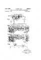
- FIG. l is a partly broken away, schematic elevation of a screw machine provided with the structure of the present invention
- FIG. 2 is an axial sectional illustration of a pair of ro- ⁇ 3,096,673 Patented July 9, 1963 "ice Z tary cams which control the gripping and feeding of the work, respectively, FIG. 2 showing a clutch structure which controls the motion transmission between these rotary cams;
- FIG. 3 is an end view of the structure of FIG. 2 as seen from the left side of FIG. 2;
- FIG. 1a is a schematic elevation of the structure operating the carriage
- FIG. 4 is a transverse sectional elevation ⁇ of the structure of FIG. 2 taken along lines 4 4 of FIG. 2 in the direction of the arrows, and it will be noted that FIG. 2 is a section taken along line 2-2 of FIG. 4 in the direction of the arrows;
- FIG. 5 shows the structure of FIG. 2 in a different position from that illustrated in FIG. 2, the clutch of FIGS. 2 and 5 being disengaged in the position of the parts illustrated in FIG. 5 and being engaged in the position of the parts illustrated in F-IG. 2;
- I FIG. -6 is a diagram showing a development of a cam of the structure of FIGS. 2 and 5 which controls the operation of the clutch;
- FIG. 7 is a fragmentary sectional elevation of the workturning structure of the present invention, FIG. 7 being taken along line 7-7 of FIG. 8 in the direction of the arrows;
- FIG. 8 is a partly sectional plan view of the structure i of FIG. 7, the part of FIG. ⁇ 8 which is in section being taken along line 8-8 of FIG. 7;
- yFIGS. 9-13 respectively illustrate schematically successive stages in the operation of the structure of the invention.
- FIG. 1 there is illustrated therein a screw machine which includes the bed 10, the turret carriage 1,1 rotatably carrying the turret head 12 which in turn carries the several tools 15, and there is also provided the spindle assembly 16 provided with the work grippingmeans in the form of a collet 17 diagrammatically illustrated.
- the spindle is hollow and the work in the form of an elongated bar '19 is fed axially through the spindle from the rear to the front end thereof, collet 17 being located adjacent the front end of the ⁇ spindle to grip the work.
- the'front end porti'ii'uof the bar 19 projects forwardly beyond the collet 17 so as to form the workpiece 20.
- the screw machine further includes a work feeding means in the form of a work feeding carriage 21 shiftable parallel to the axis of the hollow spindle, and at its front end the spindle stock 16 carries a cut-olf tool 22 for cutting oi the workpiece 20, as is conventional.
- the machine tool also includes a carriage 23 ⁇ capable of moving ,back and forth in a direction perpendicular to the spindle axis, and this carriage 23 is provided with the Work turning means of the invention which is capable of turning each workpiece end for end, this work turning means of the invention being indicated in its entirety by the reference character 25.
- Phe machine t-ool also includes a continuously rotating drive shaft 26 which through ,a pair of meshing gears 28 and 29 transmits a drive through the clutch 30, which is only momentarily operated in a IWell known manner, on the one hand to .a cam -driving shaft 3t1 which serves to drive the rotary cams 32 and 3? ⁇ in a manner described below, .and on the other hand the clutch includes 'a clutch portion 30a of the same construction as the clutch 30 and also driven through the gears 28 Aand 29 from the drive shaft 26 for transmitting the drive through the shaft 31a to the rotary cam 34.
- the rotary cam 32 controls the actuation of the Vcollet lor work-gripping means 17 through the conventional collet operating structure 36, while the rotary cam 33 acts through the linkage 37 on the with a camming groove and turns the -bifurcated collet .113 is sta 'n control lever 36 which is supported for turning movement intermediate its ends, and the means 37 which controls the work feeding carriage is also in the form of a bifurcated lever whose turning movement is controlled by the rotation of the rotary cam 33 provided also with a camming groove.
- the rotary cam 34 serves through its camming groove to turn the bifurcated lever 38 which is pivotally connected at its upper end with a push-pull ⁇ bar 39 connected to the work turning means 25 of the invention for actuating the latter in a manner described below.
- the clutches 30 ⁇ and 30a are so-called quick-action clutches and that means that they effect a coupling through a certain angle of rotation, whereupon the ⁇ clutch is released.
- the clutch 30 is usually a 360-degree quick-action clutch and that means that the clutch is in operation through one complete revolution.
- the quick-action ⁇ clutch 30a is a 90degree clutch and that means that the clutch is operated only through an angle of 90 degrees and then released.
- a cam 110 is fastened whose circumference is engaged -by follower 111 of a follower arm 112 which is connected to a toothed ⁇ segment 115 rotationally arranged on a shaft 117.
- the carriage 23 consists of a lower carriage portion 118 and 1an upper carriage portion 119 which are slidably a1'- n I of each other.
- the lower carriage portion o the machine frame and the w g.- -side a rack upper carriage portion the tooth@ 122 meshing with the teeth of A tension spring 125 is attached to the followr ar ad urges the follower 111 against the camming surface of cam 110.
- side carriages as for instance carriage 23
- carriage 23 The operation of side carriages, as for instance carriage 23, is well known in the art and may be achieved in different ways as incorporated in many automatic screw machines as built by Brown & Sharpe Mfg. Co., Buffalo, R.I., U.S.A., or Index-Werke K.G. Hahn & Tessky, Esslingen-on-Neckar. In the aforementioned catalogue of the latter company there is shown on page 16S a FIG.-
- FIGS. 2-6 the structure for controlling the rotary cam means 32 and 33 is illustrated therein.
- the shaft 31 which drives the cam 32 xedly carries at its left end, as viewed in FIG. 2, a pinion 42 which meshes with a gear 43 which is in turn fixed to a cam 45 having a right annular camming projection, as
- FIG. 2 shows a development of the camming portion of the cam 4S.
- the transmission ratio between the pinion 42 and the gear 43 is 1 to 2, so that the cam 45 turns through one revolution while the ⁇ shaft 31 turns through two revolutions.
- a stationary pivot pin 47 turnably supports a lever 48 which at its bottom end carries a pin 49 the left free end of which, as viewed in FIG. 2, engages the camming portion of the cam 45 slidably.
- the upper end portion of the lever 4S is bifurcated, and the arms 5t) and 51 (FIG.
- a spring 58 is carried by a stationary part 46 in a bore of the latter and urges a sleeve which is slidable in this bore to the left, as viewed in FIGS. 2 and 5, against the lever 48 to urge the latter in a clock wise direction around the stationary pin 47 as viewed in FIGS. 2 and 5, so as to maintain the cam follower pin 49 in engagement with the cam 45.
- a sleeve 60 which is -axially :slidable with respect to the shaft 31 and the cam 33, and the lright ends of the keys 56 bear against the left end lof the sleeve 6G, as viewed in FIGS. 2 and 5.
- the right end of the sleeve 60 bears against additional keys 62 which Aare respectively :axially slidable in grooves 65 formed in The . Y. 32.
- cam 33 is formed with grooves 64 which when t Landung?, are in a predetermined angular position with respect to ewchother are respectively algined with and form extensions of the grooves 65 so that they keys 62 can be located in part in the grooves 65 and in part in the grooves 64 for interconnecting the cams 32 and 33 for rotation together, as illustrated in FIG. 2.
- a coil spring 66 is coiled around the shaft 31, bears with its right end against a shoulder formed in the interior of the rotary cam 32, Iand bears with its left end against the keys ⁇ 62 to urge the Ilatter to the left to the position illustrated in FIG. 2.
- the sleeve 60 is shifted to the right, .as viewed in FIGS.
- a spring-pressed detent means is provided for yieldably maintaining the rotary cam 33 in predetermined angular position, and this detent includes the spring-pressed pin 68 provided at its top end with an end portion of V-shaped configuration, as shown most clearly in FIG. 4, adapted to enter into a mating notch formed in the rotary cam 33, as illustrated in FIG. 4, for yieldably maintaining the latter in the angular position illustrated in FIG. 4.
- the rotary cam 33 which controls the feeding ofthe work and the rotary cam 32 which controls the gripping of the work are interconnected by the keys ⁇ 62 so that the clutch formed by the keys is engaged and these cams rotate together.
- the clutch element 30 is momentarily engaged so as to transmit rotation of the gear 29 to the shaft 31, and in this way the rotary cams 32 and 33 will be turned through one revolution inasmuch as the clutch structures 62, 64, 65 is engaged at .this time.
- the cam 45 will turn through only 180.
- the lever 48 will, -in accordance with the developed illustration of the cam shown in FIG. 6, karrive at the 180 position illustrated in FIG.
- the clutch 30 is again actuated so as to provide one revolution of the shaft 31, and in this way the rotary cam 32 will provide an opening and la closing of the collet 17 while the cam 33 will remain stationary and is prevented from Ibeing turned through ⁇ frictional engagement with other elements as a result of the spring-pressed detent pin 68.
- the cam 45 is again turned through 180, and is evident from FIG. 6, shortly before the single revolution of the cam is completed the follower 49 is engaged by a rising portion of the camming surface so as to place the follower 49 in zero position illustrated in FIG. 6.
- the operation of the work-turning means 25 of the invention is brought about by momentary engagement of the clutch 30a which provides a rotation of the shaft 31a in order to cause the cam 34 to turn so as to actuate the work-turning means.
- the work-turning means of the present invention includes a lower unit 70 adjustably carried by the transverse carriage 23 for adjustment along the groove 69 thereof.
- This groove is in the form of a T-slot as is conventional, and with this construction it is possible to tix the lower unit 70 in a desired position along the carriage 23, and it will be noted that the T-slot 69 extends parallel to the spindle axis.
- This lower unit 70 carries an upper unit 75 which is guided by the V-ribs and Igrooves shown in FIG.
- the unit 75 may he provided with van elongated projection of T-shaped configuration, for example, slidably received in a corresponding groove at the free end of the push-pull bar 39 so that the carriage 23 can be moved perpendicularly tothe spindle axis while the unit 75 slides with respect to the push-pull bar 39 while at the same time the movement of the push-pull bar resulting in turning of lever 38 will result in shifting of the unit 75 with respect to the unit 70 in a direction parallel to the spindle axis.
- rDhis upper unit 75 t-urnably supports in its interior a work turning shaft 77 which extends perpendicularly to the spindle yaxis.
- Sritable bearings 78 are provided to support lthe work turning shaft 77 for rotation about its axis.
- the Work turning shaft 77 carries a work holding means in the form of three springy fingers 80, 81, 82 which are respectively provided at their free ends with rollers 83, 84, 85.
- the rollers 83 and 85 carried by the springy :lingers 801 and 82 engage the workpiece 20 on the right side of itsaxis, as viewed in FIG.
- roller 84 engages the workpiece 20 at the left side of its axis, as viewed in FIG. 7, ⁇ so that the work is securely held by these fingers.
- the collet 17 ⁇ is diagrammatically' illustrated in iFIG. 7, and it is apparent that the work holding ⁇ fingers 80-82 engage the workpiece 20 at a portion thereof which extends beyond the collet 17.
- a spring 89 engages the left end face of the pinion 87 so as to urge the latter to the right, as viewed in FIG. 7.
- This pinion 87 meshes with ra rack 90 which is supported by rthe unit 75 for move ment parallel to the spindle axis, the rack 90 itself extending parallel to the ⁇ spindle axis.
- the shaft 77 also turnaibly carries a one-way drive 92 in the form of a ratchet portion 93 -iixed to the pinion 87 for turning movement therewith and ya mating ratchet portion 94 fixed directly to the sha-ft 77, the spring 89 'acting through the pinion 87 on the left ratchet portion 93 of FIG. 7 to urge the latter into engagement with the right ratchet portion 94.
- a one-way drive 92 in the form of a ratchet portion 93 -iixed to the pinion 87 for turning movement therewith and ya mating ratchet portion 94 fixed directly to the sha-ft 77, the spring 89 'acting through the pinion 87 on the left ratchet portion 93 of FIG. 7 to urge the latter into engagement with the right ratchet portion 94.
- this ratchet structure 9.2 will provide only a one-way direction of rotation of the shaft4 As is most clearly shown in FIGIBfa/spfl/S: Urges the rack l90 towardjthestop 100"S110WI1 in FIG 8, and "the rod pol-,tion :about which the spring ⁇ 89 is coiled is fixed .at one end to the rack 90 and at its opposite end carries a pair of lock nuts to adjust the position of the rack 90.
- a springpnessed detent means - is provided to cooperate through the' ratchet portion 94 of the one-way drive 92 with the shaft 77 to prevent rotation of the latter due to frictional engagement of ⁇ the elements 93 and 94 when the element 93 turns in a reverse direction during return of the parts to the position shown in F-IG. 8.
- the lower unit 70 which is directly carried by the carriage 23 fxedly. carries an arm 99 to which the'stop 100 is adjustable xed, this stop being in -t-he form of a screw member carrying a lock nut capable of fixing the stop 100 axially on the arm 99.
- This stop l100l is coaxial with and located in the path of the rack 90.
- FIGS. 7 and 8 operates in the following manner, reference being had toFIGS. 9-13 which illustrate successive stages of the oper-ation of the structure of the invention.
- the carriage 7 23 is moved up to the workpiece so that the work holding fingers Stb-82 grip the workpiece.
- the means for feeding the work is out of operation at this time due to the disengagement of the clutch elements 62, as described above.
- the workpiece 20 is cutoff from the bar d9 by the cut-off tool 22.
- the upper unit 75 is shifted by the push-pull har 39 in a direction parallel to the axis of the workpiece, to the right, as viewed in FIG. ⁇ 1.
- the turret carriage 11 is now in its rearmost position illustrated in FIG. 1.
- the end of the rack 90 will engage the stop 100', and thus the rack 90 will stop moving while the unit 75 will continue to move with respect to the rack so that the pinion 87 turns in order to turn the shaft 77 and thus turn the workpiece 20 end for end through 180.
- the bar -19 can shift rearwardly since the collet 17 is -in a disengaged position at this time, so that when the collet 17 is again actuated to grip the work, the already machined end of the workpiece 20 will be engaged by the tongues of the collet, and the other end of the workpiece will now be positioned for machining.
- the carriage 23 with the structure of the invention is shifted away from the work to the position shown in FIG. 13. Also, at this time, the drive to the rotary cam 34 is cutoff due to the disconnection of the clutch 30a.
- first rotary cam means rotating at a given speed and adapted to actuate a work-gripping means; second rotary cam means adapted to actuate a work ⁇ feeding means; clutch means transmitting a drive from said rst cam means to said second cam means when said clutch means is engaged; third rotary cam.
- rst rotary cam means adapted to actuate a work-gripping means
- second rotary lcam means coaxial with said first rotary cam means and adapted to actuate a work-feeding means
- clutch means cooperating with said first and second rotary cam means for transmitting a drive ⁇ from said first to said second rotary cam means when said clutch means is in an engaged position
- third cam means cooperating with said clutch means for controlling the engagement and disengagement thereof, said clutch means including a plurality of axially shiftable key members and spring means urging said key members Ito a rest position where they transmit the drive from said first to said second rotary cam means, so that said 4clutch means moves said key members in opposition to said spring means for disengaging the clutch
- transmission means driving said third ⁇ cam means from said first cam means at one-half of the speed of said first cam means.
- first rotary cam means adapted to actuate work-gripping means; second rotary cam means coaxial with said first rotary cam means and adapted to actuate a work-feeding means; clutch means cooperating with said first and second rotary cam means for transmitting a drive from said first to said second rotary cam means when said clutch means is in an engaged position; third cam means cooperating with said clutch means for controlling the engagement and disengagement thereof, said first rotary cam means including a tubular cam and a drive shaft extending through said tubular cam and fixed thereto for rotating the latter, said clutch means including a plurality of keys shiftable along said drive shaft for engaging or disengaging said first and second rotary cam means, said second rotary cam means also being tubular and said drive shaft extending freely therethrough, said clutch means including a sleeve slidable on said shaft between the latter and said rotary cam means and engaging said keys for shifting the latter, said clutch means also including a ring surrounding said drive shaft and having axial projections engaging said
- first rotary cam means adapted to actuate Ia work-gripping means; second rotary cam means coaxial with said first rotary cam means and adapted to actuate a work-feeding means; clutch means cooperating with said first and second rotary cam means for transmitting the drive from said first to said second rotary cam means when said clutch means is in an engaged position; third cam means cooperating with said clutch means for controlling the engagement and disengagement thereof; transmission means driving said third cam means from said first cam means at one-half the speed of the latter; Iand spring-pressed detent means cooperating with said second rotary cam means for maintaining the latter in a given angular position when said clutch means is in a disengaged position where said first rotary cam means does not drive said second rotary cam means.
- first rotary cam means adapted to actuate a work-gripping means
- Second rotary cam means adapted to actuate a work-feeding means which feeds an elongated workpiece to said Workgripping means to be gripped thereby
- clutch means having an engaged position transmitting a drive from said rst cam means to said second cam means and la disengaged position where said rst cam means rotates while said second cam means remains stationary
- third rotary cam means cooperating with said clutch means for controlling the engagement yand disengagement thereof
- transmission means driving said third rotary cam means from said tirst rotary cam means at a speed which is h-a-lf of the speed of rotation of said iirst rotary cam means so that said second rotary cam means actuates the work-feeding means to feed a workpiece to said work-gripping means only at every other actuation of the work-gripping means by said first rotary cam means; and means for turning end for end in timed relation with said c
- rst rotary earn means adapted to actuate a work-gripping means
- second rotary cam means adapted to actuate a workfeeding means which feeds an elongated bar to said workgripping means to be gripped thereby
- clutch means having an engaged position transmitting a drive from said first cam means to said second cam means and a disengaged position where said rst cam means rotates while said second cam means remains stationary
- third rotary cam means cooperating with said clutch means for controlling the engagement and disengagement thereof
- transmission means driving -said third rotary cam means from said first rotary cam means at a speed which is half of the speed of rotation of said first rotary cam means so that said second rotary 0am means actuates the work-feeding means to feed the bar to said work-gripping means only at every :other actuation of the work-gripping means by said first rotary cam means, so that the bar will be gripped by the workegripping means ionly during alternate actuations thereof while
- drive means common to and driving both said transmission means and said means for turning the workpiece end for end and for placing the workpiece in a position to be gripped a second time by the work-gripping means.
Landscapes
- Engineering & Computer Science (AREA)
- Mechanical Engineering (AREA)
- Turning (AREA)
- Transmission Devices (AREA)
Applications Claiming Priority (1)
| Application Number | Priority Date | Filing Date | Title |
|---|---|---|---|
| DEI0014942 | 1958-06-06 |
Publications (1)
| Publication Number | Publication Date |
|---|---|
| US3096673A true US3096673A (en) | 1963-07-09 |
Family
ID=7185718
Family Applications (1)
| Application Number | Title | Priority Date | Filing Date |
|---|---|---|---|
| US818712A Expired - Lifetime US3096673A (en) | 1958-06-06 | 1959-06-08 | Automatic working turning means for screw machines |
Country Status (3)
| Country | Link |
|---|---|
| US (1) | US3096673A (de) |
| CH (1) | CH369643A (de) |
| GB (1) | GB895062A (de) |
Cited By (5)
| Publication number | Priority date | Publication date | Assignee | Title |
|---|---|---|---|---|
| US3512423A (en) * | 1967-01-24 | 1970-05-19 | Schuitemaker Patents Sa | Intermittent drive mechanism having self-compensating means for offsetting the effects of developed countertorque |
| US3683724A (en) * | 1970-05-07 | 1972-08-15 | Brian Crane | Attachments for automatic lathes |
| US3714837A (en) * | 1970-06-23 | 1973-02-06 | O Jensen | Indexible clutch mechanism |
| US20060285447A1 (en) * | 2005-06-01 | 2006-12-21 | Sherman Raymond C | Automatic, lockable and engageable/disengageable media tray |
| CN111266656A (zh) * | 2019-11-22 | 2020-06-12 | 莱芜汇金金属制品股份有限公司 | 机床驱动式可伸缩刀具及用该刀具的差速器壳体加工方法 |
Citations (6)
| Publication number | Priority date | Publication date | Assignee | Title |
|---|---|---|---|---|
| US2076635A (en) * | 1935-10-17 | 1937-04-13 | Ramsey Chain Company Inc | Clutch |
| US2128186A (en) * | 1937-08-13 | 1938-08-23 | Buffalo Bolt Company | Blank reversing and shaping mechanism |
| US2392984A (en) * | 1944-05-29 | 1946-01-15 | Transmission Specialties Compa | Clutch structure |
| US2397561A (en) * | 1944-01-17 | 1946-04-02 | Joseph D Petsche | Collet tube collar |
| US2514472A (en) * | 1944-12-18 | 1950-07-11 | Bullard Co | Chuck |
| US2779956A (en) * | 1950-05-02 | 1957-02-05 | Nat Acme Co | Blank reversing means for multiple spindle machine |
-
1959
- 1959-04-10 CH CH7183559A patent/CH369643A/de unknown
- 1959-05-08 GB GB15962/59A patent/GB895062A/en not_active Expired
- 1959-06-08 US US818712A patent/US3096673A/en not_active Expired - Lifetime
Patent Citations (6)
| Publication number | Priority date | Publication date | Assignee | Title |
|---|---|---|---|---|
| US2076635A (en) * | 1935-10-17 | 1937-04-13 | Ramsey Chain Company Inc | Clutch |
| US2128186A (en) * | 1937-08-13 | 1938-08-23 | Buffalo Bolt Company | Blank reversing and shaping mechanism |
| US2397561A (en) * | 1944-01-17 | 1946-04-02 | Joseph D Petsche | Collet tube collar |
| US2392984A (en) * | 1944-05-29 | 1946-01-15 | Transmission Specialties Compa | Clutch structure |
| US2514472A (en) * | 1944-12-18 | 1950-07-11 | Bullard Co | Chuck |
| US2779956A (en) * | 1950-05-02 | 1957-02-05 | Nat Acme Co | Blank reversing means for multiple spindle machine |
Cited By (7)
| Publication number | Priority date | Publication date | Assignee | Title |
|---|---|---|---|---|
| US3512423A (en) * | 1967-01-24 | 1970-05-19 | Schuitemaker Patents Sa | Intermittent drive mechanism having self-compensating means for offsetting the effects of developed countertorque |
| US3683724A (en) * | 1970-05-07 | 1972-08-15 | Brian Crane | Attachments for automatic lathes |
| US3714837A (en) * | 1970-06-23 | 1973-02-06 | O Jensen | Indexible clutch mechanism |
| US20060285447A1 (en) * | 2005-06-01 | 2006-12-21 | Sherman Raymond C | Automatic, lockable and engageable/disengageable media tray |
| US7540491B2 (en) * | 2005-06-01 | 2009-06-02 | Hewlett-Packard Development Company, L.P. | Automatic, lockable, engageable and disengageable media tray |
| CN111266656A (zh) * | 2019-11-22 | 2020-06-12 | 莱芜汇金金属制品股份有限公司 | 机床驱动式可伸缩刀具及用该刀具的差速器壳体加工方法 |
| CN111266656B (zh) * | 2019-11-22 | 2021-02-02 | 莱芜汇金金属制品股份有限公司 | 机床驱动式可伸缩刀具及用该刀具的差速器壳体加工方法 |
Also Published As
| Publication number | Publication date |
|---|---|
| CH369643A (de) | 1963-05-31 |
| GB895062A (en) | 1962-04-26 |
Similar Documents
| Publication | Publication Date | Title |
|---|---|---|
| JPH0310442B2 (de) | ||
| US3096673A (en) | Automatic working turning means for screw machines | |
| US2576570A (en) | Screw machine | |
| US2377383A (en) | Feed control for automatic screw machines | |
| US2310259A (en) | Stock feed for automatic screw machines | |
| US5297454A (en) | Indexing device of machine tool | |
| US3988937A (en) | Device for producing feeding stroke of transfer feeder for use in transfer press | |
| US3381558A (en) | Machine tools | |
| US2007564A (en) | Lathe and like machine tool | |
| GB1072130A (en) | Improvements in machine tools | |
| US2399621A (en) | Device for automatic lathes | |
| US2239443A (en) | Transmission mechanism for lathes | |
| US3169426A (en) | Thread cutting machine | |
| US2126907A (en) | Machine for shaping helicoidal surfaces | |
| US3472104A (en) | Thread-cutting device | |
| US2347372A (en) | Automatic forming machine | |
| US2270310A (en) | Machine tool | |
| US2622454A (en) | Auxiliary transmission mechanism for milling machines | |
| US3015116A (en) | Threading attachment with change speed transmission for reversing tool spindle rotation | |
| US2501281A (en) | Gear train for machine tool slides | |
| US2507725A (en) | Gear cutting machine | |
| US1484604A (en) | Automatic screw machine | |
| US1936447A (en) | Control for hydraulic operating systems | |
| US1363751A (en) | Automatic multiple-spindle lathe | |
| US2039347A (en) | Machine for fashioning articles successively from bar stock |