US3094271A - Seal for refrigerant compressor - Google Patents
Seal for refrigerant compressor Download PDFInfo
- Publication number
- US3094271A US3094271A US209361A US20936162A US3094271A US 3094271 A US3094271 A US 3094271A US 209361 A US209361 A US 209361A US 20936162 A US20936162 A US 20936162A US 3094271 A US3094271 A US 3094271A
- Authority
- US
- United States
- Prior art keywords
- compressor
- impeller
- housing
- shaft
- valve seat
- Prior art date
- Legal status (The legal status is an assumption and is not a legal conclusion. Google has not performed a legal analysis and makes no representation as to the accuracy of the status listed.)
- Expired - Lifetime
Links
Images
Classifications
-
- F—MECHANICAL ENGINEERING; LIGHTING; HEATING; WEAPONS; BLASTING
- F25—REFRIGERATION OR COOLING; COMBINED HEATING AND REFRIGERATION SYSTEMS; HEAT PUMP SYSTEMS; MANUFACTURE OR STORAGE OF ICE; LIQUEFACTION SOLIDIFICATION OF GASES
- F25B—REFRIGERATION MACHINES, PLANTS OR SYSTEMS; COMBINED HEATING AND REFRIGERATION SYSTEMS; HEAT PUMP SYSTEMS
- F25B1/00—Compression machines, plants or systems with non-reversible cycle
- F25B1/04—Compression machines, plants or systems with non-reversible cycle with compressor of rotary type
- F25B1/053—Compression machines, plants or systems with non-reversible cycle with compressor of rotary type of turbine type
Definitions
- refrigerant may be ylost by leakage past the shaft seal lwhen the pressure in the system is above atmospheric for air could leak into the system when the pressure is below atmospheric.
- the refrigerant pressure in the system depends on the characteristics of the particular refrigerant used and the surrounding atmospheric conditions.
- This invention solves the above problems by providing a shutoif valve integral with the compressor for isolating it and its associated refrigeration system from the surrounding atmosphere. This shutoff valve will automatically close when the compressor is stopped and automatically open when the compressor is started.
- Another object .of this invention is to provide a novel shutoff means for isolating the compressor and refrigerating system when the compressor is shut down which is rendered inoperative when the compressor is operated.
- Another object of this invention is to provide a novel means for operating the shutoff device which utilizes the same medium for operating the shutoff device that is used for operating the turbine Iwhich drives the compressor.
- Another object of this invention is to provide a novel means for holding the shutoff device open lafter the compressor is shut down for the period of time required for it to coast to a' stop.
- IFIG. 1 is a longitudinal cross-.section of a turbine driven compressor embodying the novel lfeatures of this invention.
- PIG. 2 is a partial longitudinal section of the shutoff device shown in FIG. l, drawn to an enlarged scale.
- FIG. 1 a compressor having an impeller 10 of the single inlet type mounted on one end of a shaft ⁇ 12. rI'he compressor is driven by Ia turbine hav-ing a turbine wheel I11 which is mounted on the other end of the shaft y12.
- the shaft in tu-rn is rotatably mounted in the housing of the turbocornpressor unit by means of two balls bearings 131 and 14.
- the impeller rotates in a suitably shaped impeller housing 15.
- the impelleri ousing v15 is provided with an inlet 16 which is aligned with the inlet 22 of the impeller and a diffusing section 2l1 which is aligned with discharge 3,094,271 Patented June 18, 1963 ice 2 23 of the impeller. After the refrigerant ilows through the diffusing section of the casing, it flows into a scroll shaped collecting ring 20 and is discharged from the compressor through a suitable discharge conduit, not shown.
- the suction inlet 22 of the compressor is isolated from the discharge of the impeller by means of a labyrinth seal 25.
- the labyrinth seal 25 is mounted in the impeller housing 15 by any 'desired means, such as a press tit, and co-oper'ates with a cylindrical surface 33 formed on the outer periphery of the impeller .adjacent the inlet thereof.
- Another labyrinth seal 30, similar to the labyrinth seal 25, is provided for isolating the discharge 23 of the impeller from the shaft opening in the impeller housing.
- the labyrinth seal 30 is mounted in .the impeller housing .15 by any desired means, such as a press t, and co-operates Iwith a cylindrical surface ⁇ 34 which is formed on the outer periphery of an annular flange projecting from the back side of the impeller w10.
- Each of the labyrinth seals is formed from a stack of .alternate ring shaped members -32 and spacing rings 3,1 as shown in lFIG. 2.
- the stack of ring members 32 and spacing rings 31 are held together as a unit by any desired Ifastening means, such as a plurality of circumferentially spaced rivets (not shown).
- the inner diameter of theV ring shaped members 32 is slightly larger than the corresponding diameter of .the cylindrical surfaces 33 or 34 on the impeller 10.
- the :above described construction provides yan impeller V10 which may be rotated by the turbine 11 so as to draw the refrigerant in through the inlet l16 of the impeller housing and discharge it into the scroll sh-aped collecting ring 20 of the impeller housing.
- yan impeller V10 which may be rotated by the turbine 11 so as to draw the refrigerant in through the inlet l16 of the impeller housing and discharge it into the scroll sh-aped collecting ring 20 of the impeller housing.
- the labyrinth seals E25 and 30 lirni-t the escape of refrigerant from the spaces y24 and 26 to a relatively small amount.
- a shaft seal is provided on the -shaft 12. Shown is atypical face typ-e seal such as a carbon ring type of shaft seal which consists of a carbon ring 36 mounted irr the compressor Ihousing 15 and a metal ring 35 which is secured to the shaft 12.
- the carbon ring 36 is mounted in the compressor housing 'with lits left end abutting against an inwardly projecting shoulder formed in the compressor housing 15.
- the outer periphery of the carbon ring is sealed lby means of an O-ring 39, While its linner periphery is spaced from the shaft 12.
- the metal ring 35 is preferably for-med of hardened steel or a similar material While the carbon ring 36 is formed of graphitic carbon or a similar material.
- the adjacent radial surfaces 37 and 3'8 of the carbon ring 36 and the metal ring 35, respectively, are optically flat rubbing surfaces.
- a shutoff device which consists of a valve surrounding the shaft seal which is actuated by an annular piston to open when the compressor is started and spring biased to close when the compressor is stopped.
- the valve consists of a valve seat 40 shown in FIG.
- valve closure ring 41 formed preferably of slightly resilient, high temperature elastomeric material, such as Teflon or other material which is unaffected by the refrigerant, mounted on the end of lan annular piston, shown generally at 42, which is adapted to move axially in an annular ,cylinder 4'7 formed in the impeller housing 15.
- the inner diameter of the annular piston 42 is sealed by means of an O-ring 44, or equivalent means, which is mounted in the impeller housing 15.
- the outer diameter of Ithe annular piston is sealed [by means of a flexible diaphragm 43, or equivalent means, the outer edge of which is secured to the impeller housing ⁇ 15.
- the inner diameter of the diaphragm 43 is clamped between an axially extending member 42a carrying the valve ring 41 and a radially extending member 42b which are Secured together at 42a ⁇ by a press tit or other means well known in the art to ⁇ form the :annular piston 42.
- a ring type spring 45 is provided for urging the annular piston 42 to the right as shown in the drawing to -bias the valve closure ring 41 into engagement with the valve seat 40 ⁇ when the compressor is shut down.
- means are provided for introducing -a compressed fluid into the annular area 46 on the Iright-hand side of the member 42b of the annular piston 42 when the compressor is started. This fluid pressure will act in opposition to the force of the ring spring 45, thus moving the piston into the annular chamber 48 and refr-acting the valve ring -41 from the valve seat.
- a vent opening 49 which extends through the wall of the impeller housing 1'5 to a chamber 60- in the housing in which the bearings 13 and 14 are mounted.
- the vent functions to prevent -a buildup of pressure in the chamber 48 when the annular piston 42 is moved into that chamber.
- the vent opening 49 additionally functions to permit pressurized lfluid which has leaked from chamber 46 past the periphery of member 42b into .the chamber 48 to iiow through the vent to the chamber 60 in the bearing housing, thus maintaining the pressure inl chamber 48 substantially the ⁇ same -as the pressure in the housing.
- the spring 45 functions to -urge the annular piston to the right as shown Yin the drawing the vent opening 49 permits fluid to flow from the bearing housing into the chamber 48, thus relieving the partial vacuum which would otherwise hinder closing movement of the valve ring 41.
- the pressurized fluid -used to drive the turbine wheel ⁇ 11 is utilized for moving the annular piston 42 in the direction to retract the valve ring 41 from the valve seat 40.
- 'Ilhis pressurized fluid is conducted to the annular area 46 on the righthand side of the member 42b of the annular piston by means of la passageway 50 formed in the main compressor housing ⁇ and a passageway l51 formed in the .turbocompressor housing.
- a small ball check valve 54 which is actuated by a spring A55, is provided in the passageway 51 to retard the backow of tluid from the annular area 46 into the turbine housing when the turbine unit is shut down.
- the pressurized ilu-id used for driving the turbine wheel 11 is admitted to a plenum chamber 57 from which it ows into a suitable nozzle ring 58 which directs the pressurized fluid over the blades of the turbine wheel .1.1.
- a small portion of the pressurized iiuid will escape through the annular area 59 existing between the .outer periphery of the turbine wheel 11 and the inner periphery of the nozzle ring 58. After escaping through the annular area 59, the fluid will flow into an annular area 52 from which it will iiow through the ball check valve 54 Iand passageways 50 :and 51, previously described.
- the above described system thus provides a means whereby the compressor and refrigeration system will be completely isolated by means of a valve which closes when the compressor is shut down. yIn addition, this valve lis automatically opened when the compressor is started since the same medium used by the prime mover of the compressor is used to open the valve.
- the check valve ⁇ 54 closes to retard the backflow of ⁇ the pressurized uid from the annular area 46 .into the turbine housing.
- the ball of the check valve 54 is scored to deliberately provide 4a small ⁇ leakage past the valve sutiicient to gradually allow the pressure in ⁇ annular area 46 to dissipate.
- the spring 4S moves the ,annular piston 42 tto the right, as shown in the drawing, until the valve ring 41 engages the valve seat 40.
- the ⁇ retarding of the ow of tluid from the area 46 permits the compressor unit .to coast to a stop, or nearly to .a stop, before the valve ring 41 engages the valve seat ⁇ 40, thus preventing .damaging the elastomeric material in the valve ring 41.
- a compressor impeller mounted on said shaft for rotation in said impeller chamber;
- ⁇ a driving turbine operatively connected to said shaft;
- a plate member mounted on said shaft and having an annular valve seat disposed contiguous said impeller;
- first sealing means for preventing leakage of uids between said housing and said impeller chamber including piston means surrounding said shaft and having an annular valve closure member adapted to be moved into and out of engagement with said valve seat;
- a turbine driven centrifugal compressor a housing; a shaft rotatably mounted in said housing; an impeller chamber adjoining said housing; a compressor impeller mounted on said shaft for rotation in said impeller chamber; a driving turbine operatively connected to said shaft; a plate member mounted on said shaft and having an annular valve seat disposed contiguous said impeller; sealing means for preventing leakage of fluids between said housing and said impeller chamber including piston means surrounding said shaft and having an annular valve closure member adapted to be moved into and out of engagement with said valve seat; means defining a cylindrical chamber, said piston means being disposed for movement in said cylindrical chamber; resilient means engaging said piston means for biasing said valve closure member into engagement with said valve seat when the compressor is idle; means for conducting fluid under pressure from the inlet of said driving turbine to one side of said cylindrical chamber to actuate said piston means in opposition to the resilient means to move said
- a turbine driven centrifugal compressor a housing; a shaft rotatably mounted in said housing; an impeller chamber adjoining said housing; a compressor impeller mounted on said shaft for rotation in said impeller chamber; a driving turbine operatively connected to said shaft; sealing means for preventing leakage of fluids between said housing and said impeller chamber including an annular valve seat disposed on said shaft contiguous said impeller and an annular piston having an annular valve closure member adapted to be moved into and out of engagement with said valve seat; means defining a cylindrical chamber, said annular piston being disposed for movement in said cylindrical chamber; resilient means engaging said piston for biasing said valve closure member into engagement with said valve seat when the compressor is idle; means for conducting fluid under pressure from the inlet of said driving turbine to one side of said cylindrical chamber to actuate said piston in opposition to the resilient means and move said valve closure member out of engagement with said valve seat when motive fluid is admitted to the driving turbine; and means for retarding the flow of fluid from said cylindrical chamber when said driving turbine is shut down to prevent engagement of the
- a turbine driven centrifugal compressor a housing; a shaft rotatably mounted in said housing; an impeller chamber adjoining said housing; a compressor impeller mounted on said shaft for rotation in said impeller chamber;l a driving turbine operatively connected to said shaft; sealing means for preventing leakage of fluids between said housing and said impeller chamber including an annular valve seat disposed contiguous said impeller and an annular piston having an annular valve closure member adapted to be moved into and out of engagement with said valve seat;
- resilient means engaging said piston for biasing said valve closure member into engagement with said valve seat when the compressor is idle;
- passage means for conducting fluid under pressure from the inlet of said driving turbine to said operating pressure chamber to actuate said piston in opposition to the resilient means and move said valve closure member out of engagement with said valve seat when motive fluid is admitted to the driving turbine;
- an annular valve seat formed on said impeller sealing means for preventing leakage of uids between said housing and said impeller chamber including a piston surrounding said shaft and having a valve closure member adapted to be moved into and out of engagement with said valve seat;
- resilient means engaging said piston for biasing said valve closure member into engagement with said valve seat when the compressor is idle;
- passage means for conducting fluid under pressure from the inlet of said driving turbine to said operating pressure chamber to actuate said piston in opposition to the resilient means and move said valve closure member out of engagement with said valve seat when motive uid is admitted to the driving turbine;
- sealing means for preventing leakage of uids between said housing and said impeller chamber including a valve closure member adapted to be moved into and out of engagement with said valve seat;
- sealing means for preventing leakage of uids between said housing and said impeller chamber including a valve closure member adapted to be moved into and out of engagement with said valve seat;
- uid operated means for moving said valve closure member out of engagement with said valve seat when motive uid is admitted to the driving turbine;
- sealing means for preventing leakage of fluids between said housing and said impeller chamber including a valve closure member adapted Ito be moved into and out of engagement with said valve seat;
Description
June 1s, 1963 H. A, GREENWALD. 3,094,271
SEAL FOR REFRIGERANT COMPRESSOR Filed July 12, 1962 United States Patent O 3,094,271 SEAL FOR REFRIGERANT COMPRESSOR Harold A. Greenwald, Los Angeles, Calif., assigner to The Garrett Corporation, Los Angeles, Calif., a corporation of California Filed July 12, 1962, Ser. No. 209,361 8 Claims. (Cl. 230-116) This invention pertains to compressors and more particularly to turbine driven centrifugal refrigeration compressors.
This application is a continuation-impart of my copending application Serial No. 31,183, entitled Seal for Refrigerant Compressor, filed May 23, 1960, now abandoned and which in turn was a division of my application ySerial No. 629,884, entitled Seal for Refrigerant Compressor, filed December 21, 1956, now Patent No. 2,973,- i135 issued February 28,V 196.1.
In centrifugal refrigeration compressors it is desirable to provide means for isolating the compressor and the refrigeration system from the surrounding atmosphere when the compressor is shut down. If the compressor and refrigeration systems lare not isolated, refrigerant may be ylost by leakage past the shaft seal lwhen the pressure in the system is above atmospheric for air could leak into the system when the pressure is below atmospheric. The refrigerant pressure in the system depends on the characteristics of the particular refrigerant used and the surrounding atmospheric conditions.
This invention solves the above problems by providing a shutoif valve integral with the compressor for isolating it and its associated refrigeration system from the surrounding atmosphere. This shutoff valve will automatically close when the compressor is stopped and automatically open when the compressor is started.
Accordingly, it is an object of .this invention to provide a novel shutoff device for isolating the compressor and Irefrigeration system from the surrounding atmosphere in the remainder of the compressor or the bearing housing when the compressor is shut down.
Another object .of this invention is to provide a novel shutoff means for isolating the compressor and refrigerating system when the compressor is shut down which is rendered inoperative when the compressor is operated.
Another object of this invention is to provide a novel means for operating the shutoff device which utilizes the same medium for operating the shutoff device that is used for operating the turbine Iwhich drives the compressor.
Another object of this invention is to provide a novel means for holding the shutoff device open lafter the compressor is shut down for the period of time required for it to coast to a' stop.
These and other objects and advantages of this invention will be more apparent to those skilled in thel art from the following detailed `description' when taken in conjunction with Ithe lattached .drawings in which:
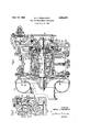
IFIG. 1 is a longitudinal cross-.section of a turbine driven compressor embodying the novel lfeatures of this invention; and
PIG. 2 is a partial longitudinal section of the shutoff device shown in FIG. l, drawn to an enlarged scale.
Referring to the drawing, there is shown in FIG. 1 a compressor having an impeller 10 of the single inlet type mounted on one end of a shaft `12. rI'he compressor is driven by Ia turbine hav-ing a turbine wheel I11 which is mounted on the other end of the shaft y12. The shaft in tu-rn is rotatably mounted in the housing of the turbocornpressor unit by means of two balls bearings 131 and 14. The impeller rotates in a suitably shaped impeller housing 15. The impelleri ousing v15 is provided with an inlet 16 which is aligned with the inlet 22 of the impeller and a diffusing section 2l1 which is aligned with discharge 3,094,271 Patented June 18, 1963 ice 2 23 of the impeller. After the refrigerant ilows through the diffusing section of the casing, it flows into a scroll shaped collecting ring 20 and is discharged from the compressor through a suitable discharge conduit, not shown.
The suction inlet 22 of the compressor is isolated from the discharge of the impeller by means of a labyrinth seal 25. The labyrinth seal 25 is mounted in the impeller housing 15 by any 'desired means, such as a press tit, and co-oper'ates with a cylindrical surface 33 formed on the outer periphery of the impeller .adjacent the inlet thereof. Another labyrinth seal 30, similar to the labyrinth seal 25, is provided for isolating the discharge 23 of the impeller from the shaft opening in the impeller housing. The labyrinth seal 30 is mounted in .the impeller housing .15 by any desired means, such as a press t, and co-operates Iwith a cylindrical surface `34 which is formed on the outer periphery of an annular flange projecting from the back side of the impeller w10. Each of the labyrinth seals is formed from a stack of .alternate ring shaped members -32 and spacing rings 3,1 as shown in lFIG. 2. The stack of ring members 32 and spacing rings 31 are held together as a unit by any desired Ifastening means, such as a plurality of circumferentially spaced rivets (not shown). The inner diameter of theV ring shaped members 32 is slightly larger than the corresponding diameter of .the cylindrical surfaces 33 or 34 on the impeller 10.
The :above described construction provides yan impeller V10 which may be rotated by the turbine 11 so as to draw the refrigerant in through the inlet l16 of the impeller housing and discharge it into the scroll sh-aped collecting ring 20 of the impeller housing. As the refrigerant is discharged through the discharge 23 of the impeller, a small amount will leak axially past the outer edges of the disch-arge :and tend to escape into the spaces 24 and 26 on the front and back side of the impeller, respectively. The labyrinth seals E25 and 30 lirni-t the escape of refrigerant from the spaces y24 and 26 to a relatively small amount.
While the above described labyrinth seal 30` prevents any substantial leakage of Ithe refrigerant from the space 26 to the back side of the compressor impeller, a small amount .of refrigerant will leak past the labyrinth seal 30. In order to prevent the escape of the refrigerant from the compressor to the atmosphere or the housing in which the bearings are mounted, a shaft seal is provided on the -shaft 12. Shown is atypical face typ-e seal such as a carbon ring type of shaft seal which consists of a carbon ring 36 mounted irr the compressor Ihousing 15 and a metal ring 35 which is secured to the shaft 12. The carbon ring 36 is mounted in the compressor housing 'with lits left end abutting against an inwardly projecting shoulder formed in the compressor housing 15. The outer periphery of the carbon ring is sealed lby means of an O-ring 39, While its linner periphery is spaced from the shaft 12. The metal ring 35 is preferably for-med of hardened steel or a similar material While the carbon ring 36 is formed of graphitic carbon or a similar material. The adjacent radial surfaces 37 and 3'8 of the carbon ring 36 and the metal ring 35, respectively, are optically flat rubbing surfaces. Thus the steel ring 35 which rotates with the shaft when Ithe unit is running and the carbon ring which does not rotate forman effective seal to prevent `any but minute amounts of the refrigerant from leaking from the system along the shaft =12. The natural lubricating properties of the carbon ring 36 together with oil mist which flows from the bearing housing through passageway/s 1-7, 18 and 119 formed in the shaft |12 provide the desired lubrication and cooling.
While the shaft seal provides an effective means for preventing all but minute amounts of leakage of refrigerant from the system when the compressor is operating, the pressure difference across the seal may be greater when the unit is idle than when it is operating. This will tend to increase leakage of refrigerant to the atmosphere on hot days, or allow the atmosphere to leak in on cold days when the refrigerant pressure is below atmospheric [or the bearing housing pressure. In order to prevent this leakage of refrigerant out or atmosphere in, a shutoff device is provided which consists of a valve surrounding the shaft seal which is actuated by an annular piston to open when the compressor is started and spring biased to close when the compressor is stopped. The valve consists of a valve seat 40 shown in FIG. 2 which is formed on the metal ring 35 adjacent the outer periphery thereof and a valve closure ring 41 formed preferably of slightly resilient, high temperature elastomeric material, such as Teflon or other material which is unaffected by the refrigerant, mounted on the end of lan annular piston, shown generally at 42, which is adapted to move axially in an annular ,cylinder 4'7 formed in the impeller housing 15. Thus the valve seat 40 rotates with the shaft when the unit is running while the valve closure ring 41 is moved laxially into :and out of engagement with the valve seat in the manner hereinafter described.
The inner diameter of the annular piston 42 is sealed by means of an O-ring 44, or equivalent means, which is mounted in the impeller housing 15. The outer diameter of Ithe annular piston is sealed [by means of a flexible diaphragm 43, or equivalent means, the outer edge of which is secured to the impeller housing `15. The inner diameter of the diaphragm 43 is clamped between an axially extending member 42a carrying the valve ring 41 and a radially extending member 42b which are Secured together at 42a` by a press tit or other means well known in the art to `form the :annular piston 42. A ring type spring 45 is provided for urging the annular piston 42 to the right as shown in the drawing to -bias the valve closure ring 41 into engagement with the valve seat 40 `when the compressor is shut down.
In order to prevent frictional damage to the valve ring 41, means are provided for introducing -a compressed fluid into the annular area 46 on the Iright-hand side of the member 42b of the annular piston 42 when the compressor is started. This fluid pressure will act in opposition to the force of the ring spring 45, thus moving the piston into the annular chamber 48 and refr-acting the valve ring -41 from the valve seat.
Communicating with the annular area 48 is a vent opening 49 which extends through the wall of the impeller housing 1'5 to a chamber 60- in the housing in which the bearings 13 and 14 are mounted. The vent functions to prevent -a buildup of pressure in the chamber 48 when the annular piston 42 is moved into that chamber. The vent opening 49 additionally functions to permit pressurized lfluid which has leaked from chamber 46 past the periphery of member 42b into .the chamber 48 to iiow through the vent to the chamber 60 in the bearing housing, thus maintaining the pressure inl chamber 48 substantially the `same -as the pressure in the housing. When the spring 45 functions to -urge the annular piston to the right as shown Yin the drawing the vent opening 49 permits fluid to flow from the bearing housing into the chamber 48, thus relieving the partial vacuum which would otherwise hinder closing movement of the valve ring 41.
As shown in FIG. 1 of the drawing, the pressurized fluid -used to drive the turbine wheel `11 is utilized for moving the annular piston 42 in the direction to retract the valve ring 41 from the valve seat 40. 'Ilhis pressurized fluid is conducted to the annular area 46 on the righthand side of the member 42b of the annular piston by means of la passageway 50 formed in the main compressor housing `and a passageway l51 formed in the .turbocompressor housing. A-s hereinafter noted, a small ball check valve 54, which is actuated by a spring A55, is provided in the passageway 51 to retard the backow of tluid from the annular area 46 into the turbine housing when the turbine unit is shut down. The pressurized ilu-id used for driving the turbine wheel 11 is admitted to a plenum chamber 57 from which it ows into a suitable nozzle ring 58 which directs the pressurized fluid over the blades of the turbine wheel .1.1. A small portion of the pressurized iiuid will escape through the annular area 59 existing between the .outer periphery of the turbine wheel 11 and the inner periphery of the nozzle ring 58. After escaping through the annular area 59, the fluid will flow into an annular area 52 from which it will iiow through the ball check valve 54 Iand passageways 50 :and 51, previously described.
The above described system thus provides a means whereby the compressor and refrigeration system will be completely isolated by means of a valve which closes when the compressor is shut down. yIn addition, this valve lis automatically opened when the compressor is started since the same medium used by the prime mover of the compressor is used to open the valve.
In operation, when the supply of pressurized uid owing to the turbine is shut off, the check valve `54 closes to retard the backflow of `the pressurized uid from the annular area 46 .into the turbine housing. However, the ball of the check valve 54 is scored to deliberately provide 4a small `leakage past the valve sutiicient to gradually allow the pressure in `annular area 46 to dissipate. As the pressure in the area 46 dissipates, the spring 4S moves the ,annular piston 42 tto the right, as shown in the drawing, until the valve ring 41 engages the valve seat 40. The `retarding of the ow of tluid from the area 46 permits the compressor unit .to coast to a stop, or nearly to .a stop, before the valve ring 41 engages the valve seat `40, thus preventing .damaging the elastomeric material in the valve ring 41.
While .only one preferred embodiment of this invention has been described in detail, it will be apparent to those skilled in the `art that many modifications and improvements can be made. Also, Iwhile the invention was described -as applied primarily to a refrigeration compressor, it can be applied to other types of centrifugal compressors.
I claim:
1. In a turbine driven centrifugal compressor:
a housing;
a shaft rotatably mounted in said housing;
an impeller chamber adjoining said housing;
a compressor impeller mounted on said shaft for rotation in said impeller chamber; `a driving turbine operatively connected to said shaft; a plate member mounted on said shaft and having an annular valve seat disposed contiguous said impeller;
first sealing means for preventing leakage of uids between said housing and said impeller chamber including piston means surrounding said shaft and having an annular valve closure member adapted to be moved into and out of engagement with said valve seat;
means defining a cylindrical chamber, said piston means being disposed for movement in said cylindrical chamber;
resilient means engaging said piston means for biasing said valve closure member into engagement with said valve seat when fthe compressor is idle;
means for conducting fluid under pressure from the inlet of said driving turbine to one side of said cylindrical chamber to actuate said piston means in opposition to the resilient means to move said valve closure member out of engagement with said valve `seat when motive fluid is admitted to the driving turbine;
means for retarding the iiow of fluid from said cylindrical chamber when said driving turbine is shut down to prevent engagement of the valve closure member with the valve seat while the compressor is coasting to a stop;
and second sealing means in series with said first seal- Iing means and including a sealing ring having a surface contacting said plate member of said first sealing means. 2. Ina turbine driven centrifugal compressor: a housing; a shaft rotatably mounted in said housing; an impeller chamber adjoining said housing; a compressor impeller mounted on said shaft for rotation in said impeller chamber; a driving turbine operatively connected to said shaft; a plate member mounted on said shaft and having an annular valve seat disposed contiguous said impeller; sealing means for preventing leakage of fluids between said housing and said impeller chamber including piston means surrounding said shaft and having an annular valve closure member adapted to be moved into and out of engagement with said valve seat; means defining a cylindrical chamber, said piston means being disposed for movement in said cylindrical chamber; resilient means engaging said piston means for biasing said valve closure member into engagement with said valve seat when the compressor is idle; means for conducting fluid under pressure from the inlet of said driving turbine to one side of said cylindrical chamber to actuate said piston means in opposition to the resilient means to move said valve closure member out of engagement with said valve seat when motive fluid is admitted to the driving turbine; and means for retarding the iiow of fluid from said cylindrical chamber when said driving turbine is shut down to prevent engagement of the valve closure member with the valve seat while the compressor 1s coasting to a stop. 3. In a turbine driven centrifugal compressor: a housing; a shaft rotatably mounted in said housing; an impeller chamber adjoining said housing; a compressor impeller mounted on said shaft for rotation in said impeller chamber; a driving turbine operatively connected to said shaft; sealing means for preventing leakage of fluids between said housing and said impeller chamber including an annular valve seat disposed on said shaft contiguous said impeller and an annular piston having an annular valve closure member adapted to be moved into and out of engagement with said valve seat; means defining a cylindrical chamber, said annular piston being disposed for movement in said cylindrical chamber; resilient means engaging said piston for biasing said valve closure member into engagement with said valve seat when the compressor is idle; means for conducting fluid under pressure from the inlet of said driving turbine to one side of said cylindrical chamber to actuate said piston in opposition to the resilient means and move said valve closure member out of engagement with said valve seat when motive fluid is admitted to the driving turbine; and means for retarding the flow of fluid from said cylindrical chamber when said driving turbine is shut down to prevent engagement of the valve closure member with fthe valve seat while the compressor is coasting to a stop. 4. In a turbine driven centrifugal compressor: a housing; a shaft rotatably mounted in said housing; an impeller chamber adjoining said housing; a compressor impeller mounted on said shaft for rotation in said impeller chamber;l a driving turbine operatively connected to said shaft; sealing means for preventing leakage of fluids between said housing and said impeller chamber including an annular valve seat disposed contiguous said impeller and an annular piston having an annular valve closure member adapted to be moved into and out of engagement with said valve seat;
means defining an operating pressure chamber, said l piston being subjected on one side to the pressure in said operating pressure chamber;
resilient means engaging said piston for biasing said valve closure member into engagement with said valve seat when the compressor is idle;
passage means for conducting fluid under pressure from the inlet of said driving turbine to said operating pressure chamber to actuate said piston in opposition to the resilient means and move said valve closure member out of engagement with said valve seat when motive fluid is admitted to the driving turbine;
and means -for retarding the ow of fluid from said operating `chamber when said driving turbine is shut down to prevent engagement of the valve closure member with the valve seat while the compressor is coasting to a stop.
5. In a turbine driven centrifugal compressor:
a housing;
a shaft rotatably mounted in said housing;
an impeller chamber contiguous said housing;
a compressor impeller mounted on said shaft for rotation in said impeller chamber;
a driving turbine operatively connected to said shaft;
an annular valve seat formed on said impeller sealing means for preventing leakage of uids between said housing and said impeller chamber including a piston surrounding said shaft and having a valve closure member adapted to be moved into and out of engagement with said valve seat;
resilient means engaging said piston for biasing said valve closure member into engagement with said valve seat when the compressor is idle;
means defining an operating pressure chamber, said pist0n lbeing subjected on one side to the pressure in said operating pressure chamber and on the opposite side to the pressure in said housing;
passage means for conducting fluid under pressure from the inlet of said driving turbine to said operating pressure chamber to actuate said piston in opposition to the resilient means and move said valve closure member out of engagement with said valve seat when motive uid is admitted to the driving turbine;
and means for retarding the ow of fluid from said operating pressure chamber when said driving turbine is shut down to prevent engagement of the valve closure member with the valve seat while the compressor is coasting to a stop.
6. In a turbine driven centrifugal compressor:
a housing;
a shaft rotatably mounted in said housing;
a-n impeller chamber contiguous said housing;
a compressor impeller mounted on said shaft for rotation in said impeller chamber;
a driving lturbine operatively connected to said shaft;
an annular valve seat disposed contiguous said impeller;
sealing means for preventing leakage of uids between said housing and said impeller chamber including a valve closure member adapted to be moved into and out of engagement with said valve seat;
resilient means for biasing said valve closure member into engagement with said valve seat when the compressor is idle;
means actuated by the uid medium utilized for operating the driving turbine for moving said valve closure member ont of engagement with said valve seat when motive fluid is admitted to the driving turbine;
and means for retarding the engagement of the valve closure member with the valve seat when the driving turbine is shut down until the compressor has coasted to a stop.
7. In a .turbine driven centrifugal compressor:
a housing;
a shaft rotatably mounted in said housing;
an impeller chamber contiguous said housing;
a compressor impeller mounted on said shaft for rotation in said impeller chamber;
a driving turbine operatively connected to said shaft;
an annular valve seat disposed contiguous said impeller;
sealing means for preventing leakage of uids between said housing and said impeller chamber including a valve closure member adapted to be moved into and out of engagement with said valve seat;
resilient means for biasing said valve closure member into engagement with said valve seat when the compressor is idle;
uid operated means for moving said valve closure member out of engagement with said valve seat when motive uid is admitted to the driving turbine;
passage means connecting said uid operated means to the inlet of said driving turbine;
and means including a check valve mounted in said passage means for retarding the escape of fluid from said uid operated means when said driving turbine is shut down to prevent engagement f the valve closure member with the valve seat while the compressor is coasting to a stop.
8. In a turbine driven centrifugal compressor:
a housing;
a shaft rotatably mounted in said housing;
an impeller chamber contiguous said housing;
a compressor impeller mounted on said shaft for rotation in said impeller chamber;
a driving turbine operatively connected to said shaft;
an annular Valve seat disposed contiguous said impeller;
sealing means for preventing leakage of fluids between said housing and said impeller chamber including a valve closure member adapted Ito be moved into and out of engagement with said valve seat;
resilient means for biasing said valve closure member into engagement with said valve seat when the compressor is idle;
and means actuated by the fluid medium utilized for operating the driving turbine for moving said valve closure member out of engagement with said valve seat when motive uid is admitted to the driving turbine.
References Cited in the file of this patent UNITED STATES PATENTS 2,393,691 Karassik Jan. 29, 1946 2,646,999 Barske July 28, 1953 2,873,986 Murray Feb. 17, 1959 FOREIGN PATENTS 228,945 Great Britain May 21, 1925
Claims (1)
1. IN A TURBINE DRIVEN CENTRIFUGAL COMPRESSOR: A HOUSING; A SHAFT ROTATABLY MOUNTED IN SAID HOUSING; AN IMPELLER CHAMBER ADJOINING SAID HOUSING; A COMPRESSOR IMPELLER MOUNTED ON SAID SHAFT FOR ROTATION IN SAID IMPELLER CHAMBER; A DRIVING TURBINE OPERATIVELY CONNECTED TO SAID SHAFT; A PLATE MEMBER MOUNTED ON SAID SHAFT AND HAVING AN ANNULAR VALVE SEAT DISPOSED CONTIGUOUS SAID IMPELLER; FIRST SEALING MEANS FOR PREVENTING LEAKAGE OF FLUIDS BETWEEN SAID HOUSING AND SAID IMPELLER CHAMBER INCLUDING PISTON MEANS SURROUNDING SAID SHAFT AND HAVING AN ANNULAR VALVE CLOSURE MEMBER ADAPTED TO BE MOVED INTO AND OUT OF ENGAGEMENT WITH SAID VALVE SEAT; MEANS DEFINING A CYLINDRICAL CHAMBER, SAID PISTON MEANS BEING DISPOSED FOR MOVEMENT IN SAID CYLINDRICAL CHAMBER;
Priority Applications (1)
| Application Number | Priority Date | Filing Date | Title |
|---|---|---|---|
| US209361A US3094271A (en) | 1962-07-12 | 1962-07-12 | Seal for refrigerant compressor |
Applications Claiming Priority (1)
| Application Number | Priority Date | Filing Date | Title |
|---|---|---|---|
| US209361A US3094271A (en) | 1962-07-12 | 1962-07-12 | Seal for refrigerant compressor |
Publications (1)
| Publication Number | Publication Date |
|---|---|
| US3094271A true US3094271A (en) | 1963-06-18 |
Family
ID=22778469
Family Applications (1)
| Application Number | Title | Priority Date | Filing Date |
|---|---|---|---|
| US209361A Expired - Lifetime US3094271A (en) | 1962-07-12 | 1962-07-12 | Seal for refrigerant compressor |
Country Status (1)
| Country | Link |
|---|---|
| US (1) | US3094271A (en) |
Cited By (4)
| Publication number | Priority date | Publication date | Assignee | Title |
|---|---|---|---|---|
| US3635581A (en) * | 1969-08-22 | 1972-01-18 | Air Reduction | High-pressure centrifugal pump |
| US4285632A (en) * | 1979-02-28 | 1981-08-25 | United Aircraft Products, Inc. | Oiling system for rotor bearings |
| US4364717A (en) * | 1978-07-03 | 1982-12-21 | Barmag Barmer Maschinenfabrik Ag | Exhaust gas turbocharger |
| US20150086332A1 (en) * | 2013-09-25 | 2015-03-26 | Hyundai Wia Corporation | Turbocharger |
Citations (4)
| Publication number | Priority date | Publication date | Assignee | Title |
|---|---|---|---|---|
| GB228945A (en) * | 1924-02-08 | 1925-05-21 | International General Electric Company | |
| US2393691A (en) * | 1943-11-03 | 1946-01-29 | Worthington Pump & Mach Corp | Pumping unit |
| US2646999A (en) * | 1948-01-23 | 1953-07-28 | Filton Ltd | Fluid seal |
| US2873986A (en) * | 1954-10-21 | 1959-02-17 | Murray William | Combined fluid and contact seal |
-
1962
- 1962-07-12 US US209361A patent/US3094271A/en not_active Expired - Lifetime
Patent Citations (4)
| Publication number | Priority date | Publication date | Assignee | Title |
|---|---|---|---|---|
| GB228945A (en) * | 1924-02-08 | 1925-05-21 | International General Electric Company | |
| US2393691A (en) * | 1943-11-03 | 1946-01-29 | Worthington Pump & Mach Corp | Pumping unit |
| US2646999A (en) * | 1948-01-23 | 1953-07-28 | Filton Ltd | Fluid seal |
| US2873986A (en) * | 1954-10-21 | 1959-02-17 | Murray William | Combined fluid and contact seal |
Cited By (4)
| Publication number | Priority date | Publication date | Assignee | Title |
|---|---|---|---|---|
| US3635581A (en) * | 1969-08-22 | 1972-01-18 | Air Reduction | High-pressure centrifugal pump |
| US4364717A (en) * | 1978-07-03 | 1982-12-21 | Barmag Barmer Maschinenfabrik Ag | Exhaust gas turbocharger |
| US4285632A (en) * | 1979-02-28 | 1981-08-25 | United Aircraft Products, Inc. | Oiling system for rotor bearings |
| US20150086332A1 (en) * | 2013-09-25 | 2015-03-26 | Hyundai Wia Corporation | Turbocharger |
Similar Documents
| Publication | Publication Date | Title |
|---|---|---|
| US3468548A (en) | Rotating shaft seal | |
| US4477223A (en) | Sealing system for a turboexpander compressor | |
| US3004782A (en) | Shaft seal | |
| US2936715A (en) | Seal assembly | |
| US2853020A (en) | Shaft seal | |
| US2973136A (en) | Compressor | |
| US3410565A (en) | Centrifugal and face contact seal | |
| US4722663A (en) | Seal-off mechanism for rotating turbine shaft | |
| US3526408A (en) | Mechanical seal construction | |
| CN108019430B (en) | Fluid machinery lubricating system assembly | |
| US3062554A (en) | Rotary shaft seal | |
| US2953416A (en) | Thrust bearing construction | |
| US2835514A (en) | Rotary shaft seal | |
| US4544167A (en) | Face seal with resilient packing ring forcing face rings together | |
| US3094271A (en) | Seal for refrigerant compressor | |
| US2956502A (en) | Fuel pump | |
| US3096985A (en) | Empergency shaft sealing device | |
| US3028181A (en) | Seals for rotating shafts | |
| US3731940A (en) | Elastomer seal with a plurality of annular ribs for a rotating shaft of a centrifugal pump or the like | |
| US2775400A (en) | Turbine driven fan unit | |
| US3540742A (en) | Mechanical seal construction | |
| US2973135A (en) | Seal for refrigerant compressor | |
| US3479040A (en) | Mechanical seal construction | |
| US3071347A (en) | Variable area nozzle device | |
| US2502173A (en) | Fluid balancing means |