US3083384A - Wipers for end lasting machines - Google Patents
Wipers for end lasting machines Download PDFInfo
- Publication number
- US3083384A US3083384A US152135A US15213561A US3083384A US 3083384 A US3083384 A US 3083384A US 152135 A US152135 A US 152135A US 15213561 A US15213561 A US 15213561A US 3083384 A US3083384 A US 3083384A
- Authority
- US
- United States
- Prior art keywords
- wipers
- side surfaces
- wiper
- front side
- rear side
- Prior art date
- Legal status (The legal status is an assumption and is not a legal conclusion. Google has not performed a legal analysis and makes no representation as to the accuracy of the status listed.)
- Expired - Lifetime
Links
Images


Classifications
-
- A—HUMAN NECESSITIES
- A43—FOOTWEAR
- A43D—MACHINES, TOOLS, EQUIPMENT OR METHODS FOR MANUFACTURING OR REPAIRING FOOTWEAR
- A43D23/00—Single parts for pulling-over or lasting machines
- A43D23/02—Wipers; Sole-pressers; Last-supports; Pincers
Definitions
- This invention relates to improved wipers for usein a shoe end lasting machine such as the heel seat lastingmachine disclosed in pending application Serial No. 107,156, filed May 2, 1961.
- End lasting wipers conventionally have fiat coplanar undersurfaces and forwardly divergent front side surfaces adapted to embrace the end of a last having a shoe upper and insole thereon and have drive means for translating the wipers forwardly across, the insole and swinging the front side surfaces toward each other to cause the divergent. side surfaces to cross the last and wipe the lasting margin of the upper against the insole.
- rear side surfaces of the wipers that are located rearwardly of the front side surfaces. The separation of the rear side surfaces creates a gap, and the portion of the, wiped in margin that underlies this gap does not have pressure applied to it during the forward movement of the wipers and during the application of bedding pressure after the wipers have completed their forward movement.
- This problem has been mitigated by covering the gap in allpositions of the wipers. This has been done by providing a bridging element on One of the wipers that extends from its rear side surface past the rear side surface of the other wiper into a recess in the undersurface of the other wiper.
- the bridging element has a fiat undersurface that is coplanar with the wiper undersurfaces and is so constructed that it, together with the wipers, completely covers the wiped in upper margin during the forward movement of the wipers and after the wipers have completed their forward movement.
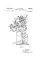
- FIG. 1 is a side elevation of the heel seat lasting mane
- FIG. 2 is a front elevation of the machine
- FIG. 3 is a detail in section of a part of the machine
- FIG. 4 is a plan view of the wiper drive means
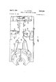
- FIG. 5 is an exploded perspective. view of the wipers
- FIG. 6 is a representation looking from above of the wipers and the shoe to be lasted with the wipers in their retracted position;
- FIG. 7 is a view similar to FIG. 6 but showing the wipers in their forward position.
- FIG. 8 is a sectional side elevation of the machine parts at the completion of' the wiping operation.
- the wipers of the, instant invention may be. used in a heel seat lasting mac ine such as that shown in pending application Serial No. 107,156, filed May 2, 1961.
- the machine comprises a post 10 to the upper endof which is secured a last supporting plate 12 and a lastpin 14, (FIG. 2).
- An upper tensioning unit 16 is mounted on the post 16.
- the unit 16 comprises a front pincers 18, two side pincers 2t and a toe rest 22.
- a block 24 is swingably mounted on the post 14 for oscillation about the axis of; the post.
- the block has rails 26 connected thereto. and extending-forwardly thereof on which the unit 16 is slidably mounted for movement toward and away from the post 16.
- a pair of air actuated motors 28. are pivoted to the rails 26 and have piston rods 30 connected to the. unit 16 to effect movement'of the unit 16 along the rails 24.
- the pincers 1 8 and 20- are mounted on a bar 32, and an air actuated motor (not shown) is connected to the bar 32 to elfect 2 upward and downward movement of the pincers 1 8 and 20 with respect to the rails 26.
- the post 10 and the upper tensioning unit 16 carried thereby are swingably mounted on a pivot 33 for bodily movement toward and away from a heel seat lasting unit 34 mounted in the frame 36 of the machine.
- the unit 34 comprises a u-shaped heel clamping pad 38. made of flexible material such as. leather and wipers 40' and 42 mounted; in wiper cams 44.
- a hold-down unit 46 is mounted on the frame above the unit 34.
- the unit 46 comprises a hold-down foot 48' that is normally located with its bottom slightly below the bottoms of the wipers and which is elevated from its normal position upon actuation of an air operated motor 50.
- the post, 10 is pivotally' connected to a pitman 52 which-in turn is operatively connected to a rack 54 where by reciprocation of the rack. by an air actuated motor 56 effects movement of the post 10 and the upper tensioning unit 16 carried thereby toward and away from the heel seat lastingunit 34 and the hold-down unit 46.
- the pivot 33 is located at the end ofthe piston rod 58 of an air actuated motor- 60, the piston rod being guided in a bearing 62 mounted on the frame 36 of the machine.
- the heel seat lasting unit 34 is supported on a main slide plate -64 that is slidably mounted for forward and rearward movement on gibs 66 inthe frame 36 (FIG. 3).
- a block 68 is secured to the plate 64 and is slidable in a slot 70 formed in a table 72, which table forms a part of the frame 36.
- a floating actuator 74 is se cured to the block 68.
- the actuator 74 comprises a bar 76- depending from and rigid with the block 68.
- An air operated motor 78 is pivoted to the bar 76 and has a piston rod 80 extending upwardly therefrom.
- a pairof toggle links 82 and 84 are pivoted at their adjoining ends to the piston rod 80- and are respectively pivoted at their opposite ends to the bar 76 and to a block 86, that is located in a fixed position in the machine. Actuation of the motor 78 to openor close the toggle linkage formed by the members 80, 82 and 84 will cause the main slide plate 64 and the members carried thereby to move forwardly or rearwardly in the frame.
- the legs, 88 of the clamping pad 38 are connected to levers 90 (FIG. 2), and the levers form part of a driving mechanism (not shown) mounted on the main slide plate 64 for moving the pad 38 forwardly and the padlegs 88'toward each other to clamp the heel portion of a shoe upper against a shoe last as described below.
- a bridge d2 is anchored at its ends to the main slide plate 64 and extends thereover *(FIG. 4.).
- An air oneratedmotor Q4.' (FIG. l) is secured to a rib 96 ,at the rear of the main slide plate 6.4.
- the piston rod 98. of the motor 94-. has a rack 1G4 thereon that is in mesh with a gear 102 rotatably mounted: beneath the bridge 92 on a pin 164- fixed in the bridge.
- a wiper supporting slide plate 196 is slidably supported on gibs 16.8 in the frame 36.
- the plate 166- has a slot llli extending transversely to the rack lililwhich receives an eccentrically mounted crank pin 112,.
- the pistonv rod 98 hasanenlargement' 114 to which are pivoted the ends of links 116.
- the opPOsite ends of the links 116 are pivoted to.
- the wiper cams 4.4- whichmount the wiper-s 40: and 42;.
- the wiper cams 4.4 have curved cam. slots 118.v with a center of curvature. at the point or vertex where the wipersdiverge from each other, indicated. by the numeral 120*;
- the wiper cams rest on the plate- 106, and the plate- 106 has rollers 122 extending-upwardly therefrom into the cam slots 1-18;
- a bridging element 140 is secured in a recess in the undersurface 134- of the wiper 42 and is received in a recess 142 in the undersurface 132 of the wiper 4h.
- undersurface of the bridging element is flat and coplanar with the undersurface 134.
- the rear end 144 of the bridge is on an arc whose center of curvature lies at the vertex 129.
- the end 144 starts at the front side surface 130 of the wiper 42, arcs rearwardly to intersect the rear side surface 126,
- ⁇ then intersects the rear side surface 124 of the wiper 49, arcs forwardly in the recess 142 and terminates in a lip 146 that extends forwardly of the front side surface 123.
- the rear end 148 of the recess 142 is also on an arc whose center of curvature'is at the vertex 120 and is contiguous to the bridging element end 144 to accommodate the bridging element.
- the portion 159 of the front end of the bridging element 14% that lies within the wiper 42 is coextensive with the front side surface 139 of the wiper 4-2, and the remainder of the front end of the bridging element forms the front of the lip 146 and extends forwardly of the front side surface 128 of the wiper do.
- a last 151 is provided having an insole 152 mounted on its bottom and an upper 1S4 draped thereon.
- a liner 156 is secured to the heel of the upper to engage the heel of the last, and a counter 15% is located in the pocket formed between the upper and liner, the counter having the characteristics described in the aforementioned application Serial No. 107,156 and in pending application Serial No. 80,919, filed January 5, 1961.
- the last is placed bottom-up on the last supporting plate 12 with the pin 14 entering the conventional last pin hole in the last.
- the toe portions of the upper and last are supported on the toe roller 22, the toeof the upper margin is inserted between the jaws of the front pincers 18, the forepart portions of the upper margin are inserted between the jaws of the side pincers 20, and the pincers are actuated to cause their jaws to grip the upper margin.
- the motors 28 are now actuated to move the upper tensioning unit 16 and the pincers 18, 20 carried thereby forwardly to stretch the upper tightly about the heel of the last and tension-mold the counter to the shape of the heel of the last.
- the motor 56 is now actuated to swing the post and the upper tensioning unit 16 carried thereby toward the heel seat lasting unit 34 to a position adjacent to but not in contact with the heel clamping pad 38 wherein the post It] is substantially in alignment with the hold-down foot 48.
- the motor 60 is now actuated to raise the post to bring the insole 152 in engagement with the hold-down foot 48, after which the pincers :18 and 20 are raised upwardly in unison to apply an upward tension to the margin of the upper 154 at its toe and forepart portions to thereby stretch the upper tightly on the last and assemble it in proper position for the heel seat lasting operation.
- the motor 78 is now actuated to straighten the toggle links 82, 84 and thereby move the block 63 and the heel seat lasting unit 34 carried thereby from its normal,
- the motor 94 is actuated to advance the piston rod 98, the rack 1049 and the piston rod enlargement 114 to cause the wipers to move from the PEG. 6 position to the FIG. 7 position to wipe or fold the margin of the upper 154 and counter 153 down upon the insole 152, as indicated in FIGS. 7 and 8.
- the wiping ressure completes the melding of the counter and causes the counter, through adhesive on its surfaces, to bond the wiped-in margin of the upper to the insole.
- the forward movement of the piston rod 98, through the links 116, causes the front side surfaces 123, 13h to swing toward each other about the vertex 12s with the slots 113 swinging forwardly with respect to the rollers 122 and causes the surfaces 128, 13h to approach each other in their wiping movement across the bottom of the last.
- the forward movement of the piston rod 33, through the rack 160, the gear 1G2, the slot 118 and the pin 112 also causes the plate res to move forwardly thereby providing a forward, translatory movement of the wipers as well as in inward movement about the vertex 12%.
- the portions of the wiper undersurfaces adjacent the vertex 12% cross the heel of the last along its median, and, durin g the inward swinging movement of the wipers, the lip 14o retreats within the recess 142, due to the concentricity of the bridge end 14-4 and the slots 118, so that at the completion of the forward wiper movement the forward end of the lip 1% is coextensive with the front side surface 128 of the wiper 4%.
- the bridging element 14o thereby serves to cover the gap created by the separation of the rear side surfaces 124, 126 of the wipers 4t 42 so that all of the wiped in upper margin is covered by a uniplanar surface.
- a lug on the piston rod actuates a three way valve 162 which actuates the motor 50 to raise the hold-down foot 48 to the position indicated in FIG. 8.
- the motor 69 now applies upward pressure by the last directly against the wipers to provide an overwiping and bedding pressure between the wipers and the wiped in margin of the upper during the latter part of the Wiper stroke and also after the termination of the Wiper stroke.
- the pincers 18, 20 are now opened to release the toe and forepart portions of the upper margin, the pincers are lowered to their initial positions on the upper tensioning unit 16, the clamping pad 38 is returned to its retracted position in the heel seat lasting unit 34, the motor 78 is actuated to return the heel seat lasting unit to its initial out-ofthe-way position, the motors 28 are actuated to return the upper tensioning unit 16 to its original position, the
- motor 60 is actuated to lower the post to lower the shoe and last away from the wipers 40, 42, the motor 94 is actuated to retract the wipers, the motor 50 is actuated to lower the hold-down foot 48 to its initial position, and the motor 56 is actuated to swing the post It and the upper tensioning unit 16 carried thereby to its initial position.
- an end lasting machine that includes: a shoe support for supporting a last having a shoe upper and insole mounted thereon; a pair of symmetrically disposed wipers, each wiper having a front side surface and a rear side surface located rearwardly of the front side surface, the front side surfaces being forwardly divergent to embrace the last and the rear side surfaces being in opposed relation; and means connected to the wipers to translate them forwardly across the insole and to concomitantly swing the front side surfaces toward each other and the rear side surfaces away from each other about a vertex located on the line of symmetry of the wipers no further rearwardly than the rear side surfaces to cause the front side surfaces to fold the lasting margin of the upper against the insole; the improvement comprising: a recess in a first one of said wipers; a bridging element on the second wiper extending from its rear side surface past the rear side surface of the first Wiper into said recess with the rear end of the bridging element contiguous to the rear end of the recess,
- an end lasting machine that includes: a shoe support for supporting a last having a shoe upper and insole mounted thereon; a pair of symmetrically disposed wipers, each wiper having a front side surface and a rear side surface located rearwardly of the front side surface, the front side surfaces being forwardly divergent to embrace the last and the rear side surfaces being in opposed relation; and means connected to the wipers to translate them forwardly across the insole from a retracted position to a forward position and to concomitantly swing the front side surfaces toward each other and the rear side surfaces away from each other to thereby cause the front side surfaces to fold the lasting margin of the upper against the insole; the improvement comprising: a bridging element in a first one of said wipers extending from its rear side surface past the rear side surface of the second wiper, the bridging element being so constructed that in the retracted position of the wipers it has a lip projecting forwardly of the front side surface of the second wiper and the lip retreats within the second wiper during the
- an end lasting machine that includes: a shoe support for supporting a last having a shoe upper and insole mounted thereon; a pair of symmetrically disposed wipers, each wiper having a front side surface and a rear side surface located rearwardly of the front side surface, the front side surfaces being forwardly divergent to embrace the last and the rear side surfaces being in opposed relation; and means connected to the wipers to translate them forwardly across the insole and to concomitantly swing the front side surfaces toward each other and the rear side surfaces away from each other about a vertex located at the juncture of the front and rear side surfaces to cause the front side surfaces to fold the lasting margin of the upper against the insole; the improvement comprising: a recess in a first one of said wipers; a bridging element on the second wiper extending from its rear side surface past the rear side surface of the first wiper into the recess with the rear end of the bridging element contiguous to the rear end of the recess, said bridging element end and rece
- an end lasting machine that includes: a shoe support for supporting a last having a shoe upper and insole mounted thereon; a pair of symmetrically disposed wipers having flat coplanar undersurfaces, each wiper having a front side surface and a rear side surface located rearwardly of the front side surface, the front side surfaces being forwardly divergent to embrace the last and the rear side surfaces being in opposed relation; and means connected to the Wipers to translate them forwardly across the insole and to concomitantly swing the front side surfaces toward each other and the rear side surfaces away from each other about a vertex located on the line of symmetry of the wipers no further rearwardly than the rear side surfaces to cause the front side surfaces to fold the lasting margin of the upper against the insole; the improvement comprising: a recess in the undersurface of a first one of said wipers; a bridging element on the second wiper, having an undersurface that is coplanar with the wiper undersurfaces, extending from the rear side surface of the second wiper past the rear side side
- an end lasting machine that includes: a shoe support for supporting a last having a shoe upper and insole thereon; a pair of symmetrically disposed wipers having flat coplanar undersurfaces, each wiper having a front side surface and a rear side surface located rearwardly of the front side surface, the front side surfaces being forwardly divergent to embrace the last and the rear side surfaces being in opposed relation; and means connected to the wipers to translate them forwardly across the insole from a retracted position to a forward position and to concomitantly swing the front side surfaces toward each other and the rear side surfaces away from each other about a vertex located on the line of symmetry of the wipers no further rearwardly than the rear side surfaces to cause the front side surfaces to fold the lasting margin of the upper against the insole; the improvement comprising: a recess in the undersurface of a first one of said wipers; a bridging element on the second wiper, having an undersurface that is coplanar with the wiper undersurfaces, extending from the
Landscapes
- Footwear And Its Accessory, Manufacturing Method And Apparatuses (AREA)
Description
April 2, 1963 P. L. DE PESA WIPERS FOR END LASTING MACHINES 6 Sheets-Sheet 1 Filed Nov. 10. 1961 //v I/EN 70R Pefer L. DePesa B/WZYW AT Y April 2, 1963 Pl 1.. DE PESA 3, 3, 4
WIPERS FOR END LASTING MACHINES Filed Nov. 10, 1961 6 Sheets-Sheet 2 GJ 5/8 0 O O I r 9 J O G 3 April 2, 1963 P. L. DE PESA WIPERS FOR END LASTING MACHINES 6 Sheets-Sheet 4 Filed NOV. 10, 1961 April 2, 1963 P. L. DE PESA 3,083,384
WIPERS FOR END LASTING MACHINES Filed Nov. 10, 1961 6 Sheets-Sheet 5 April 2, 1963 P. L. DE PESA 3,083,384
WIPERS FOR END LASTING MACHINES F'iled Nov 10, 1961 6 Sheets-Sheet 6 FIG-8 United htates Patent 3,083,364 WIPERS FOR END LASTING MACHENES Peter L. De Pesa, West Quincy, Mass, assignor to Jacob S. Kamhorian, West Newton, Mass. Filed Nov. 19, 1961, Set. N0. 152,135 7 Qlaitns. (Cl. 1212.5)
This invention relates to improved wipers for usein a shoe end lasting machine such as the heel seat lastingmachine disclosed in pending application Serial No. 107,156, filed May 2, 1961.
End lasting wipers conventionally have fiat coplanar undersurfaces and forwardly divergent front side surfaces adapted to embrace the end of a last having a shoe upper and insole thereon and have drive means for translating the wipers forwardly across, the insole and swinging the front side surfaces toward each other to cause the divergent. side surfaces to cross the last and wipe the lasting margin of the upper against the insole. However, during the inward movement of the front side surfaces, there is also outward movement, of rear side surfaces of the wipers that are located rearwardly of the front side surfaces. The separation of the rear side surfaces creates a gap, and the portion of the, wiped in margin that underlies this gap does not have pressure applied to it during the forward movement of the wipers and during the application of bedding pressure after the wipers have completed their forward movement.
This problem has been mitigated by covering the gap in allpositions of the wipers. This has been done by providing a bridging element on One of the wipers that extends from its rear side surface past the rear side surface of the other wiper into a recess in the undersurface of the other wiper. The bridging element has a fiat undersurface that is coplanar with the wiper undersurfaces and is so constructed that it, together with the wipers, completely covers the wiped in upper margin during the forward movement of the wipers and after the wipers have completed their forward movement.
Referring to the accompanying drawings:
FIG. 1 is a side elevation of the heel seat lasting mane;
FIG. 2 is a front elevation of the machine;
FIG. 3 is a detail in section of a part of the machine;
FIG. 4 is a plan view of the wiper drive means;
FIG. 5 is an exploded perspective. view of the wipers;
FIG. 6 is a representation looking from above of the wipers and the shoe to be lasted with the wipers in their retracted position;
FIG. 7 is a view similar to FIG. 6 but showing the wipers in their forward position; and
FIG. 8, is a sectional side elevation of the machine parts at the completion of' the wiping operation.
As aforesaid, the wipers of the, instant invention may be. used in a heel seat lasting mac ine such as that shown in pending application Serial No. 107,156, filed May 2, 1961. The machine comprises a post 10 to the upper endof which is secured a last supporting plate 12 and a lastpin 14, (FIG. 2). An upper tensioning unit 16 is mounted on the post 16. The unit 16 comprises a front pincers 18, two side pincers 2t and a toe rest 22. A block 24 is swingably mounted on the post 14 for oscillation about the axis of; the post. The block has rails 26 connected thereto. and extending-forwardly thereof on which the unit 16 is slidably mounted for movement toward and away from the post 16. A pair of air actuated motors 28. are pivoted to the rails 26 and have piston rods 30 connected to the. unit 16 to effect movement'of the unit 16 along the rails 24. The pincers 1 8 and 20- are mounted on a bar 32, and an air actuated motor (not shown) is connected to the bar 32 to elfect 2 upward and downward movement of the pincers 1 8 and 20 with respect to the rails 26.
The post 10 and the upper tensioning unit 16 carried thereby are swingably mounted on a pivot 33 for bodily movement toward and away from a heel seat lasting unit 34 mounted in the frame 36 of the machine. The unit 34 comprises a u-shaped heel clamping pad 38. made of flexible material such as. leather and wipers 40' and 42 mounted; in wiper cams 44. A hold-down unit 46 is mounted on the frame above the unit 34. The unit 46 comprises a hold-down foot 48' that is normally located with its bottom slightly below the bottoms of the wipers and which is elevated from its normal position upon actuation of an air operated motor 50.
The post, 10 is pivotally' connected to a pitman 52 which-in turn is operatively connected toa rack 54 where by reciprocation of the rack. by an air actuated motor 56 effects movement of the post 10 and the upper tensioning unit 16 carried thereby toward and away from the heel seat lastingunit 34 and the hold-down unit 46. The pivot 33 is located at the end ofthe piston rod 58 of an air actuated motor- 60, the piston rod being guided in a bearing 62 mounted on the frame 36 of the machine.
The heel seat lasting unit 34 is supported on a main slide plate -64 that is slidably mounted for forward and rearward movement on gibs 66 inthe frame 36 (FIG. 3). A block 68 is secured to the plate 64 and is slidable in a slot 70 formed in a table 72, which table forms a part of the frame 36. A floating actuator 74 is se cured to the block 68. The actuator 74 comprises a bar 76- depending from and rigid with the block 68. An air operated motor 78 is pivoted to the bar 76 and has a piston rod 80 extending upwardly therefrom. A pairof toggle links 82 and 84 are pivoted at their adjoining ends to the piston rod 80- and are respectively pivoted at their opposite ends to the bar 76 and to a block 86, that is located in a fixed position in the machine. Actuation of the motor 78 to openor close the toggle linkage formed by the members 80, 82 and 84 will cause the main slide plate 64 and the members carried thereby to move forwardly or rearwardly in the frame.
The legs, 88 of the clamping pad 38 are connected to levers 90 (FIG. 2), and the levers form part of a driving mechanism (not shown) mounted on the main slide plate 64 for moving the pad 38 forwardly and the padlegs 88'toward each other to clamp the heel portion of a shoe upper against a shoe last as described below.
A bridge d2 is anchored at its ends to the main slide plate 64 and extends thereover *(FIG. 4.). An air oneratedmotor Q4.' (FIG. l) is secured to a rib 96 ,at the rear of the main slide plate 6.4. The piston rod 98. of the motor 94-.has a rack 1G4 thereon that is in mesh with a gear 102 rotatably mounted: beneath the bridge 92 on a pin 164- fixed in the bridge. A wiper supporting slide plate 196 is slidably supported on gibs 16.8 in the frame 36. The plate 166- has a slot llli extending transversely to the rack lililwhich receives an eccentrically mounted crank pin 112,. dependingfrom th ge r 162;. The pistonv rod 98 hasanenlargement' 114 to which are pivoted the ends of links 116. The opPOsite ends of the links 116 are pivoted to. the wiper cams 4.4- whichmount the wiper-s 40: and 42;. The wiper cams 4.4 have curved cam. slots 118.v with a center of curvature. at the point or vertex where the wipersdiverge from each other, indicated. by the numeral 120*; The wiper cams rest on the plate- 106, and the plate- 106 has rollers 122 extending-upwardly therefrom into the cam slots 1-18;
With the wipers 40-, 42 mounted in the machine in their retracted positions, they respectively have rear side faces 124 and 128 and the surfaces 126 and 139 meet 7 at the aforementioned vertex 1-259.
A bridging element 140 is secured in a recess in the undersurface 134- of the wiper 42 and is received in a recess 142 in the undersurface 132 of the wiper 4h. The
undersurface of the bridging element is flat and coplanar with the undersurface 134. The rear end 144 of the bridge is on an arc whose center of curvature lies at the vertex 129. a
With the wipers in their retracted position, the end 144 starts at the front side surface 130 of the wiper 42, arcs rearwardly to intersect the rear side surface 126,
{then intersects the rear side surface 124 of the wiper 49, arcs forwardly in the recess 142 and terminates in a lip 146 that extends forwardly of the front side surface 123. The rear end 148 of the recess 142 is also on an arc whose center of curvature'is at the vertex 120 and is contiguous to the bridging element end 144 to accommodate the bridging element. The portion 159 of the front end of the bridging element 14% that lies within the wiper 42 is coextensive with the front side surface 139 of the wiper 4-2, and the remainder of the front end of the bridging element forms the front of the lip 146 and extends forwardly of the front side surface 128 of the wiper do.
A last 151 is provided having an insole 152 mounted on its bottom and an upper 1S4 draped thereon. A liner 156 is secured to the heel of the upper to engage the heel of the last, and a counter 15% is located in the pocket formed between the upper and liner, the counter having the characteristics described in the aforementioned application Serial No. 107,156 and in pending application Serial No. 80,919, filed January 5, 1961. The last is placed bottom-up on the last supporting plate 12 with the pin 14 entering the conventional last pin hole in the last. The toe portions of the upper and last are supported on the toe roller 22, the toeof the upper margin is inserted between the jaws of the front pincers 18, the forepart portions of the upper margin are inserted between the jaws of the side pincers 20, and the pincers are actuated to cause their jaws to grip the upper margin. The motors 28 are now actuated to move the upper tensioning unit 16 and the pincers 18, 20 carried thereby forwardly to stretch the upper tightly about the heel of the last and tension-mold the counter to the shape of the heel of the last. The motor 56 is now actuated to swing the post and the upper tensioning unit 16 carried thereby toward the heel seat lasting unit 34 to a position adjacent to but not in contact with the heel clamping pad 38 wherein the post It] is substantially in alignment with the hold-down foot 48. The motor 60 is now actuated to raise the post to bring the insole 152 in engagement with the hold-down foot 48, after which the pincers :18 and 20 are raised upwardly in unison to apply an upward tension to the margin of the upper 154 at its toe and forepart portions to thereby stretch the upper tightly on the last and assemble it in proper position for the heel seat lasting operation. The motor 78 is now actuated to straighten the toggle links 82, 84 and thereby move the block 63 and the heel seat lasting unit 34 carried thereby from its normal,
rearward, out-of-the-way position to a position adjacent the shoe and last. The driving mechanism for the heel clamping pad 33 is now actuated to cause the pad to move forwardly and the pad 'legs 88 to move inwardly thereby causing the pad to clamp the heel of the upper against the last as indicated in phantom in FIG. 6 and described below.
A. compression mold the counter 153 to the shape of the last.
At the completion of the clamping operation, the motor 94 is actuated to advance the piston rod 98, the rack 1049 and the piston rod enlargement 114 to cause the wipers to move from the PEG. 6 position to the FIG. 7 position to wipe or fold the margin of the upper 154 and counter 153 down upon the insole 152, as indicated in FIGS. 7 and 8. The wiping ressure completes the melding of the counter and causes the counter, through adhesive on its surfaces, to bond the wiped-in margin of the upper to the insole. The forward movement of the piston rod 98, through the links 116, causes the front side surfaces 123, 13h to swing toward each other about the vertex 12s with the slots 113 swinging forwardly with respect to the rollers 122 and causes the surfaces 128, 13h to approach each other in their wiping movement across the bottom of the last. The forward movement of the piston rod 33, through the rack 160, the gear 1G2, the slot 118 and the pin 112 also causes the plate res to move forwardly thereby providing a forward, translatory movement of the wipers as well as in inward movement about the vertex 12%. The portions of the wiper undersurfaces adjacent the vertex 12% cross the heel of the last along its median, and, durin g the inward swinging movement of the wipers, the lip 14o retreats within the recess 142, due to the concentricity of the bridge end 14-4 and the slots 118, so that at the completion of the forward wiper movement the forward end of the lip 1% is coextensive with the front side surface 128 of the wiper 4%. The bridging element 14o thereby serves to cover the gap created by the separation of the rear side surfaces 124, 126 of the wipers 4t 42 so that all of the wiped in upper margin is covered by a uniplanar surface. The elimination of this gap and the provision of a substantially continuous planar surface bearing against the upper margin provides for a wiping operation that effectively flattens the upper margin against the insole during the wiping op eration and during the application of bedding pressure Since the slot extends normal to the path of movement of the piston rod 98, the movement of the slot from the rightward position of FIG. 4 to the leftward position indicated in phantom causes the plate 1% initially to move forwardly almost as fast as the piston rod 98 and then to gradually slow down, until, towards the end of the stroke of the piston rod 93, the plate has substantially no forward movement. The result of this is that, initially, the wipers move forward with substantially no forward movement about the vertex 120, and at the end of the wiper stroke the wipers move toward each other about the vertex with very little forward movement. This produces a wiping action where the force created by the wipers in moving across the edge of the insole 152 at any given point is substantially radial to the curvature of the insole at that point.
During the forward stroke of the piston rod 3 a lug on the piston rod actuates a three way valve 162 which actuates the motor 50 to raise the hold-down foot 48 to the position indicated in FIG. 8. The motor 69 now applies upward pressure by the last directly against the wipers to provide an overwiping and bedding pressure between the wipers and the wiped in margin of the upper during the latter part of the Wiper stroke and also after the termination of the Wiper stroke.
This concludes the lasting operation. The pincers 18, 20 are now opened to release the toe and forepart portions of the upper margin, the pincers are lowered to their initial positions on the upper tensioning unit 16, the clamping pad 38 is returned to its retracted position in the heel seat lasting unit 34, the motor 78 is actuated to return the heel seat lasting unit to its initial out-ofthe-way position, the motors 28 are actuated to return the upper tensioning unit 16 to its original position, the
motor 60 is actuated to lower the post to lower the shoe and last away from the wipers 40, 42, the motor 94 is actuated to retract the wipers, the motor 50 is actuated to lower the hold-down foot 48 to its initial position, and the motor 56 is actuated to swing the post It and the upper tensioning unit 16 carried thereby to its initial position.
It should be understood that the present disclosure is for the purpose of illustration only and that this invention includes all modifications that fall within the scope of the appended claims. Terms such as front, forwardly and under are merely indicative of the rela- -tive paths of movement and the positions of the machine parts and should be so construed.
I claim:
1. In an end lasting machine that includes: a shoe support for supporting a last having a shoe upper and insole mounted thereon; a pair of symmetrically disposed wipers, each wiper having a front side surface and a rear side surface located rearwardly of the front side surface, the front side surfaces being forwardly divergent to embrace the last and the rear side surfaces being in opposed relation; and means connected to the wipers to translate them forwardly across the insole and to concomitantly swing the front side surfaces toward each other and the rear side surfaces away from each other about a vertex located on the line of symmetry of the wipers no further rearwardly than the rear side surfaces to cause the front side surfaces to fold the lasting margin of the upper against the insole; the improvement comprising: a recess in a first one of said wipers; a bridging element on the second wiper extending from its rear side surface past the rear side surface of the first Wiper into said recess with the rear end of the bridging element contiguous to the rear end of the recess, said bridging element end and recess end being located on an arc whose center of curvature lies at said vertex.
2. In an end lasting machine that includes: a shoe support for supporting a last having a shoe upper and insole mounted thereon; a pair of symmetrically disposed wipers, each wiper having a front side surface and a rear side surface located rearwardly of the front side surface, the front side surfaces being forwardly divergent to embrace the last and the rear side surfaces being in opposed relation; and means connected to the wipers to translate them forwardly across the insole from a retracted position to a forward position and to concomitantly swing the front side surfaces toward each other and the rear side surfaces away from each other to thereby cause the front side surfaces to fold the lasting margin of the upper against the insole; the improvement comprising: a bridging element in a first one of said wipers extending from its rear side surface past the rear side surface of the second wiper, the bridging element being so constructed that in the retracted position of the wipers it has a lip projecting forwardly of the front side surface of the second wiper and the lip retreats within the second wiper during the movement of the wipers from their retracted position to their forward position.
3. In an end lasting machine that includes: a shoe support for supporting a last having a shoe upper and insole mounted thereon; a pair of symmetrically disposed wipers, each wiper having a front side surface and a rear side surface located rearwardly of the front side surface, the front side surfaces being forwardly divergent to embrace the last and the rear side surfaces being in opposed relation; and means connected to the wipers to translate them forwardly across the insole and to concomitantly swing the front side surfaces toward each other and the rear side surfaces away from each other about a vertex located at the juncture of the front and rear side surfaces to cause the front side surfaces to fold the lasting margin of the upper against the insole; the improvement comprising: a recess in a first one of said wipers; a bridging element on the second wiper extending from its rear side surface past the rear side surface of the first wiper into the recess with the rear end of the bridging element contiguous to the rear end of the recess, said bridging element end and recess end being located on an arc whose center of curvature lies at said vertex.
4. In an end lasting machine that includes: a shoe support for supporting a last having a shoe upper and insole mounted thereon; a pair of symmetrically disposed wipers having flat coplanar undersurfaces, each wiper having a front side surface and a rear side surface located rearwardly of the front side surface, the front side surfaces being forwardly divergent to embrace the last and the rear side surfaces being in opposed relation; and means connected to the Wipers to translate them forwardly across the insole and to concomitantly swing the front side surfaces toward each other and the rear side surfaces away from each other about a vertex located on the line of symmetry of the wipers no further rearwardly than the rear side surfaces to cause the front side surfaces to fold the lasting margin of the upper against the insole; the improvement comprising: a recess in the undersurface of a first one of said wipers; a bridging element on the second wiper, having an undersurface that is coplanar with the wiper undersurfaces, extending from the rear side surface of the second wiper past the rear side surface of the first wiper into said recess with the rear end of the bridging element contiguous to the rear end of the recess, said bridging element end and recess end being located on an arc whose center of curvature lies at said vertex.
5. In an end lasting machine that includes: a shoe support for supporting a last having a shoe upper and insole thereon; a pair of symmetrically disposed wipers having flat coplanar undersurfaces, each wiper having a front side surface and a rear side surface located rearwardly of the front side surface, the front side surfaces being forwardly divergent to embrace the last and the rear side surfaces being in opposed relation; and means connected to the wipers to translate them forwardly across the insole from a retracted position to a forward position and to concomitantly swing the front side surfaces toward each other and the rear side surfaces away from each other about a vertex located on the line of symmetry of the wipers no further rearwardly than the rear side surfaces to cause the front side surfaces to fold the lasting margin of the upper against the insole; the improvement comprising: a recess in the undersurface of a first one of said wipers; a bridging element on the second wiper, having an undersurface that is coplanar with the wiper undersurfaces, extending from the rear side surface of the second wiper past the rear side surface of the first wiper into said recess with the rear end of the bridging element being contiguous to the rear end of the recess, said bridging element end and recess end being located on an arc whose center of curvature lies at said vertex; and a lip on the bridging element that, in the retracted position of the wipers, projects forwardly of the front side surface of the first wiper.
6. The lasting machine according to claim 5 where said vertex is located at the juncture of the front side surfaces and rear side surfaces.
7. The lasting machine according to claim 6 wherein the front end of the bridging element is substantially coextensive with the front side surface of the second wiper and, in the forward position of the wipers, is substantially coextensive with the front side surface of the first wiper.
References Cited in the file of this patent UNITED STATES PATENTS
Claims (1)
1. IN AN END LASTING MACHINE THAT INCLUDES: A SHOE SUPPORT FOR SUPPORTING A LAST HAVING A SHOE UPPER AND INSOLE MOUNTED THEREON; A PAIR OF SYMMETRICALLY DISPOSED WIPERS, EACH WIPER HAVING A FRONT SIDE SURFACE AND A REAR SIDE SURFACE LOCATED REARWARDLY OF THE FRONT SIDE SURFACE, THE FRONT SIDE SURFACES BEING FORWARDLY DIVERGENT TO EMBRACE THE LAST AND THE REAR SIDE SURFACES BEING IN OPPOSED RELATION; AND MEANS CONNECTED TO THE WIPERS TO TRANSLATE THEM FORWARDLY ACROSS THE INSOLE AND TO CONCOMITANTLY SWING THE FRONT SIDE SURFACES TOWARD EACH OTHER AND THE REAR SIDE SURFACES AWAY FROM EACH OTHER ABOUT A VERTEX LOCATED ON THE LINE OF SYMMETRY OF THE WIPERS NO FURTHER REARWARDLY THAN THE REAR SIDE SURFACES TO CAUSE THE FRONT SIDE SURFACES TO FOLD THE LASTING MARGIN OF THE UPPER AGAINST THE INSOLE; THE IMPROVEMENT COMPRISING: A RECESS IN A FIRST ONE OF SAID WIPERS; A BRIDGING ELEMENT ON THE SECOND WIPER EXTENDING FROM ITS
Priority Applications (1)
| Application Number | Priority Date | Filing Date | Title |
|---|---|---|---|
| US152135A US3083384A (en) | 1961-11-10 | 1961-11-10 | Wipers for end lasting machines |
Applications Claiming Priority (1)
| Application Number | Priority Date | Filing Date | Title |
|---|---|---|---|
| US152135A US3083384A (en) | 1961-11-10 | 1961-11-10 | Wipers for end lasting machines |
Publications (1)
| Publication Number | Publication Date |
|---|---|
| US3083384A true US3083384A (en) | 1963-04-02 |
Family
ID=22541650
Family Applications (1)
| Application Number | Title | Priority Date | Filing Date |
|---|---|---|---|
| US152135A Expired - Lifetime US3083384A (en) | 1961-11-10 | 1961-11-10 | Wipers for end lasting machines |
Country Status (1)
| Country | Link |
|---|---|
| US (1) | US3083384A (en) |
Cited By (1)
| Publication number | Priority date | Publication date | Assignee | Title |
|---|---|---|---|---|
| EP0585982A1 (en) * | 1992-09-04 | 1994-03-09 | OFFICINE MECCANICHE MOLINA & BIANCHI S.p.A. | Apparatus for folding the edge of a vamp on the last of a shoe-making machine |
Citations (3)
| Publication number | Priority date | Publication date | Assignee | Title |
|---|---|---|---|---|
| US689476A (en) * | 1901-03-18 | 1901-12-24 | Sophian E Fischer | Gun-sight. |
| US2221864A (en) * | 1939-06-17 | 1940-11-19 | United Shoe Machinery Corp | Lasting machine |
| US3016551A (en) * | 1960-11-23 | 1962-01-16 | United Shoe Machinery Corp | Transparent lasting machine wipers |
-
1961
- 1961-11-10 US US152135A patent/US3083384A/en not_active Expired - Lifetime
Patent Citations (3)
| Publication number | Priority date | Publication date | Assignee | Title |
|---|---|---|---|---|
| US689476A (en) * | 1901-03-18 | 1901-12-24 | Sophian E Fischer | Gun-sight. |
| US2221864A (en) * | 1939-06-17 | 1940-11-19 | United Shoe Machinery Corp | Lasting machine |
| US3016551A (en) * | 1960-11-23 | 1962-01-16 | United Shoe Machinery Corp | Transparent lasting machine wipers |
Cited By (1)
| Publication number | Priority date | Publication date | Assignee | Title |
|---|---|---|---|---|
| EP0585982A1 (en) * | 1992-09-04 | 1994-03-09 | OFFICINE MECCANICHE MOLINA & BIANCHI S.p.A. | Apparatus for folding the edge of a vamp on the last of a shoe-making machine |
Similar Documents
| Publication | Publication Date | Title |
|---|---|---|
| US3963840A (en) | Cement lasting the side and heel portions of a shoe assembly | |
| US3083384A (en) | Wipers for end lasting machines | |
| US3126563A (en) | Wipers with gap covering bridge | |
| US3082449A (en) | Lasting machines | |
| US3009182A (en) | Method of toe lasting | |
| US2271682A (en) | Counter former | |
| US3818526A (en) | Pulling and lasting machines | |
| US3115649A (en) | Heel clamp | |
| US3386115A (en) | Shoe end lasting with pronged wipers | |
| US2134148A (en) | Lasting machine | |
| US3931788A (en) | Adhesive extruding nozzle-guidance arrangements | |
| US2308271A (en) | Method of and means for shaping and smoothing shoe uppers | |
| US3091786A (en) | Apparatus for lasting pointed toe shoes | |
| US3241164A (en) | Lasting machine having spindle brake | |
| US2131837A (en) | Toe lasting mechanism | |
| US1063271A (en) | Toe-spreader. | |
| US2194892A (en) | Machine for molding counter stiffeners | |
| US3546727A (en) | Lasting machine having upper conforming yoke | |
| US3149354A (en) | Hold-down for lasting machine | |
| US3271799A (en) | Adhesive activator for shoe lasting machines | |
| US2258600A (en) | Upper shaping machine | |
| US3051969A (en) | Shoe conforming and wiper heating apparatus | |
| US1197439A (en) | Upper-forming machine. | |
| GB1158743A (en) | Lasting Machine | |
| US1722499A (en) | Lasting machine |