US3083383A - Staple lasting machine - Google Patents
Staple lasting machine Download PDFInfo
- Publication number
- US3083383A US3083383A US787034A US78703459A US3083383A US 3083383 A US3083383 A US 3083383A US 787034 A US787034 A US 787034A US 78703459 A US78703459 A US 78703459A US 3083383 A US3083383 A US 3083383A
- Authority
- US
- United States
- Prior art keywords
- wipers
- rib
- margin
- last
- insole
- Prior art date
- Legal status (The legal status is an assumption and is not a legal conclusion. Google has not performed a legal analysis and makes no representation as to the accuracy of the status listed.)
- Expired - Lifetime
Links
Images


Classifications
-
- A—HUMAN NECESSITIES
- A43—FOOTWEAR
- A43D—MACHINES, TOOLS, EQUIPMENT OR METHODS FOR MANUFACTURING OR REPAIRING FOOTWEAR
- A43D21/00—Lasting machines
- A43D21/12—Lasting machines with lasting clamps, shoe-shaped clamps, pincers, wipers, stretching straps or the like for forming the toe or heel parts of the last
- A43D21/127—Lasting machines with lasting clamps, shoe-shaped clamps, pincers, wipers, stretching straps or the like for forming the toe or heel parts of the last with wipers
Definitions
- This invention relates to apparatus, for operating on the ends of shoes, of the kind disclosed in a pending application for United States patent, Serial No. 778,188, filed December 4, 1958, in the names of Robert B. Dunlap and Jacob S. Kamborian, now Patent No. 3,011,186, granted December 5, 1961, and, in particular, to mechanism adapted to be employed in conjunction with that machine for setting staples or equivalent attaching elements through the margin of the upper after it has been stressed inwardly over the shoulder of the last into engagement with the insole rib and optionally to trim the excess margin.
- the principal objects of the invention are to provide improved staple driving mechanism for use in conjunction with the aforesaid machine in which the staples will be driven into the insole rib substantially perpendicular to the curvature thereof at the point of driving regardless of the angular position of the wipers; to provide staple driving mechanism which will set the staple through the margin and rib close to the base of the latter; to provide staple driving mechanism which can be put into operation, or not, so that the machine may optionally be used as disclosed in the aforesaid application for cement lasting or welt lasting; to provide staple driving mechanism which is of relatively simple design and can be incorporated in a conventional toe lasting machine without impairing its use for cement lasting; and to provide staple driving mechanism for automatically setting the staples when the wipers become engaged with the insole rib.
- the machine has means for mounting a last, upon which the upper and insole are assembled, means angularly movable about a point on a median line of the last to close about the ends thereof, means for effecting relative movement of the last and members relative to each other to bring the members into engagement with the upper at the base of the insole rib, and staple driving means carried by the members operable when they engage the margin at the base of the rib to drive staples through the margin into the rib.
- the aforesaid members are wipers, have concave leading edges and are angularly movable so as to conform to the shape of the toe and the driving mechanism is so disposed on the Wipers as to drive the staples through the leading edges of the wipers in a plane parallel to the bottom of the last, substantially perpendicular to the curvature of the insole rib at their point of engagement therewith, so as to set the staples close to the base of the rib.
- One or more driving mechanisms may be associated with each wiper for driving one or more staples into the toe at each side of the tip.
- knives are mounted on the wipers or carriers substituted therefor and the means mounting the last includes a jaw having engagement with the insole and parts, one of which engages the inner side of the rib and the other of which projects forwardly above the. rib and cooperates with the knives to shear the margin.
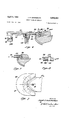
- FIG. 1 is a plan view of a part of the toe lasting machine shown in the aforementioned pending application, with the cap at the toe of the machine removed so as to show the wipers and the mechanism which effects linear and angular movement of the wipers into engagement with the toe of the last;
- FIG. 2 is a plan view of the wipers to much larger scale with the wiper operating mechanism omitted, showing the staple driving mechanism;
- FIG. 3 is a section to even larger scale taken on the line 3-3 of FIG. 2, through one of the staple driving mechanisms;
- FIG. 3a is a fragmentary section taken on the line I'm-3a of FIG. 3;
- FIG. 4 is an elevation to much smaller scale of the motor means for operating the staple driving means
- FIG. 5 is a plan View of Wiper blades provided with a staple driving mechanism for driving four staples into the work;
- FIG. 6 is a plan view of the bottom of a shoe at the toe showing staples driven through the lasting margin into the insole rib;
- FIG. 7 is a plan view of trimming means which may be used in conjunction with the wipers for trimming the excess margin substantially simultaneously with the staple operation;
- FIG. 8 is a vertical section to anenlarged scale of the toe wiping and trimming means and the staple driving means
- FIG. 9 is a fragmentary section showing the trimmer in operation.
- FIG. 10 is an elevation of one element of the clamps showing the starting switch forinitiating operation of the machine when the. shoe is mounted in readiness to be operated upon, taken on the line 10-10 of FIG. 7.
- FIG. 4 there is shown in dot and dash lines a frame 10 which supports a pair of toe clamps12 and 14, a heel clamp 16 and a pair of wipers 13 for movement relative to each other to stress an upper heightwise of the last and inwardly over the bottom.
- the wipers 18-18 are fastened respectively in a pair of cam plates 29-20 supported on a slide plate 22 for bodily movementtowa-rd the end of the last and for g m nt on the slide plate. to close the wipers about the end of the last,
- the angular movement is eifected by means of curved cam slots 24-24 and links 26-26 and the linear movement is effected by levers 28-28.
- the links and levers 26-26 and 28-28 are connected to a head 30 slidable in a slot in the plate 22, the head in turn being fastened to the end of a piston rod 32 protruding from a fluid pressure operated cylinder 34.
- Each of the Wiper blades 18 contains a narrow elongate T-shaped slot 36 disposed at such an angle that the mouth of the slot opens through the leading edge of the wiper blade substantially at right angles to the curvature of the leading edge at that point.
- a T-shaped driving member 33 (FIG. 3a) is arranged to slide in the slot 36 and has fastened to its underside a pin 40 which is engaged with an ,arcuate groove 42 formed in a block 44 situated beneath the wipers (FIG. 3). The block 44 is fastened to a-post 46 (FIG.
- a slide bar 48 which is disposed in a horizontal guide passage 50 so that the block 44 is constrained to move horizontally along the median line lengthwise of the last.
- the lower end of the post 46 is pivotally connected at 52 to a driving arm 54, which in turn is pivotally connected at its lower end to one endof a link 56, the opposite end of which is pivotally connected to the frame of the machine.
- the forward end of a piston rod 58 is pivotally connected to the driving arm 54 intermediate its ends and motion is imparted to the piston rod by a fluid pressure operated cylinder 60 which is pivotally connected at its rear end to the frame of the machine. By admitting a pressure fluid to the cylinder 60 the driving arm 54 may be moved forwardly and rearwardly so as to impart corresponding movement to the block 44. Forward movement of the block 44 will impart movement to the pins 40 and hence to the driving members 38.
- the arcu-ate groove 42 in the block 44 permits the maintenance of a driving connection between the driving arm 54 and the staple driving members 38 regardless of the angular position of the Wipers, for as the wipers are closed about the end of the shoe the pins 40 slide within the arcuate slot 42 so that they are always in alignment with the longitudinal axis of the drivers and so that movement of the block 44 forwardly imparts movement to the drivers through the pins at the particular angle at which theyhappen to be disposed at any given time.
- Staples s are supplied to the driving members 38 through slots 62 (FIGS. 2 and 3) in the wiper blades which have communication with the passages 36 and vertically disposed staple magazines 64 fastened to the wipers for movement therewith by screws'66.
- Each magazine is adapted to receive a stick of lightly attache-d staples 6'8, such as are conventionally available for staple driving devices and the stick is pressed downwardly into the magazine 'by a follower 70 backed by a spring 72.
- the driving member 38 moves forwardly it detaches the lowermost staple from the stick and drives it into the work. When it returns the next staple descends into the passage in readiness for the next forward movement of the driving member.
- the pins 40 slide in the slot 42 toward the lengthwise median line of the last.
- the jaw 12 is shaped so that its edge engages the inner side of the inseam rib r (FIG. 3) and may, if desired, have a concave surface 74 for assisting in turning the legs of the stapleinwardly.
- FIG. 2 there are two staple driving mechanisms, one associated with each wiper blade, and for most purposes a single staple driven into the lasting margin through the rib, one at each side of the tip, sufiices to hold the upper taut without need for a lasting wire or additional fastening means until the welt can be attached.
- the upper material is very thin and hence has no body for holding its shape or is heavy and stubborn to shaping it may be desirable to insert additional'staples between those inserted at either side of the toe and the pulling over tacks t shown in FIG. 6.
- additional staple driving mechanism shown in dotted lines in FIG. 5, identical with that described above, to be operated automatically as heretofore explained to drive two more staples, one at each side of the tip, so that there are two staples at each side betwen the tip and the pulling over tacks.
- Fluid pressure is supplied to the cylinder 60 by appropriate valves and valve operating solenoids when the wipers reach the innermost extent of their wiping movement and are engaged with the insole rib. This may conveniently'be affected by a switch added to the timer T of the aforesaid toe lasting machine which supplies current to the coil of a solenoid operated valve to supply the pressure fluid to the cylinder, at one end to advance the driving member and at the opposite end to retract it.
- the stapling means is shown in combination with wiping means and it is customary to remove the shoe from the machine after the upper is wiped inwardly against the rib and stapled thereto and place it in a trimming machine for removing the excess marginal material. It is a further object of this invention to add a trimmer to the wipers so that trimming can be accomplished simultaneously with the wiping and stapling operation without transfer to another machine. This may be done by fastening a trimming blade to each of the wiper blades so as to be movable therewith, or by removing the wipers and substituting therefor trimmer carrying supports which operate to impart wiping action to the margin as trimming is effected.
- FIGS. 7 to 10 inclusive there is shown a pair of carrier plates 82-82 which may be bolted to the cam plates 2tl20, shown in FIG. 1, so as to be movable about the end of the shoe.
- the plates"82-82 there are fastened trimming knives 8484, preferably so as to be readily removable for replacement as they become dull.
- the clamp '12 shown in FIG. 4, is replaced by a clamp 12a, containing a groove 86 in its edge face, a forwardly extending lip '88 at the top side of the groove and a forwardly extending lip 99 at the bottom side of the groove.
- the lip 90 bears against the inside of the insole rib r and the lip 88 projects over the upper edgeof the rib.
- the undersurface of the lip 88 lies substantially in the plane of the upper surface of the knives 8484 and forms a shearing surface, the lip 88 holding the marginal material of the upper upright so that it can be sheared off by the forward movement of the knives 8484.
- the groove 86 provides a space for movement of the knives inwardly beyond the edge of the lip 88.
- each carrier 82 contains passages 92 for staples.
- a driver 94 is arranged to slide in the passage for driving staples supplied thereto through the forward end of the carrier and through the margin and insole rib against the clamp 12a.
- the rear ends of the drivers, of which there are two, as shown herein, are provided with pins 96 which engage an arcuate groove 98 in a block 164 which corresponds to the block 44 previously described.
- the staples S are supplied to the passages 92 at the undersides of the carriers 8282 from magazines 102-402,, as distinguished from the upper side.
- the lip 90 contains recesses 104 for turning the legs of the staples as they are driven through the rib into engagement with it.
- the trimming means When the trimming means is added to the end lasting and stapling machine described above, operation of the machine is initiated in the usual manner by push button vcontrol.
- the trimming means is embodied in an end lasting and stapling machine independently of the aforesaid end lasting machine operation may be initiated by a microswitch 105 mounted in the clamp 12a, with its trip 1% aligned with a pin slidable in a passage in the clamp, with its forward end projecting slightly beyond the lip 9%.
- the insole rib r pushes the pin 108 rearwardly, thus actuating the trip of the switch element 106.
- a toe lasting machine for operating on welt-type shoes, means mounting a last with a margined upper and a ribbed insole assembled thereon, and a pair of wipers for movement linearly and 'angularly into engagement with the end of the last to stress the margin of the upper over the shoulder into engagement with the insole rib, a passage in each wiper disposed substantially perpendicular to the edge through which it emerges, said passages being movable with the wipers so that their ends are substantially perpendicular to the curvature of the rib at their place of contact therewith, a driver operable in each passage and movable with the wipers and relative thereto, a block containing an arcuate groove, a pin on each driver extending into said arcuate groove, said groove permitting the pin and groove connection to be main tained regardless of the angular disposition of the wipers, and means for effecting linear movement of the block axially of the last to accomplish driving of the drivers.
- a toe lasting machine for operating a welt-type shoes, means mounting a last with a margined upper and a ribbed insole assembled thereon, and a pair of wipers movable linearly and angularly into engagement with the end of the last to stress the margin of the upper over the shoulder into engagement with the insole rib, a passage in each wiper disposed substantially perpendicular to the edge through which it emerges, said passages being movable with the wipers so that their ends are substantially perpendicular to the curvature of the insole rib at their place of contact with the rib, a driver operable in each passage and movable with the wiper and relative thereto, a block containing an arcuate groove having its center of curvature on a line extending lengthwise of the last, a pin on each driver engaged with said groove, said groove permitting the pins to remain therein regardless of the angular disposition of the wipers, and a fluid pressure operated motor for effecting movement of the block axially of
- Apparatus according to claim 2, wherein the means mounting the last includes an anvil engaged with the insole rib at the inner side.
- a machine for fastening the margin of an upper to the rib of an insole comprising a support for holding the last bottom side up with a ribbed insole and upper assembled thereon, a pair of wipers, means for supporting the wipers for angular movement relative to the last to close them about the toe and to stress the upper inwardly against the insole rib, a passage in each wiper substantially perpendicular to the leading edge for receiving a staple for sliding movement in a plane substantially parallel to the bottom of the last, a T-shaped driver disposed in the passage for advancing the staple along the passage, a driving arm pivotally connected at its upper end to the stem of the T-shaped driver, a link pivotally connected at one end to the lower end of the driving arm and at its other end to the frame, a piston rod pivotally connected to the driving .arm intermediate its ends and a cylinder containing the piston rod and means !for supplying fluid pressure to the cylinder to effect reciprocation of the rod.
- a machine for operating on the ends of shoes means mounting a last with a margined upper and a ribbed insole assembled thereon, and instrumentalities for operating on the upper, means for etfecting relative movement of the mounting means and the instrumentalities to gather the margin about the end and force it into the corner at the base of the insole rib, means carried by the instrumental-ides to drive staples through the margin while it is engaged with the rib, and means carried by the mounting means engageable by the insole rib when the last is mounted thereon to initiate operation of the machine.
- a machine for operating on the ends of shoes means mounting a last with a margined upper and a ribbed insole assembled thereon, and instrumentalities for operating on the upper, said instrumentalities including trimming means, means for effecting relative movement of the mounting means and instrumentalities to gather the margin about the end to press it into engagement with the insole rib and to trim off the excess margin at the edge of the rib, and staple driving means carried by the instrumentalities operable when the latter move into engagement with the rib to drive staples through the margin into the rib.
- means mounting a last with a margined upper and a ribbed insole assembled thereon, and instrumentalities for operating on the upper, said instrumentalities comprising carrier members movable about the end of the last and operable by such movement to stress the margin inwardly over the shoulder into engagement with the insole rib, trimming means mounted on said carrier and movable therewith for trimming the excess margin above the insole rib, and staple driving mechanism mounted on said carriers and movable therewith to drive staples through the margin into the insole rib.
- a machine for operating on the toe of a welt shoe means mounting a last with a margined upper and a ribbed insole assembled thereon, and instrumentalities for ope-rating on the upper, said mounting means including a clamp engaged with the insole at the inner side of the insole rib, and said instrumentalities including trimming means, means for effecting relative movement of the mounting means and the instrumentalities to gather the margin about the toe, and press it into engagement with the insole rib, and simultaneously to advance the trimming means against the margin supported by the clamp, and staple driving means carried by the instrumentalities operable when the instrumentalities are engaged by the margin at the base of the insole rib to drive staples therethrough, and means for eifecting operation of the staple driving means.
- a machine for operating on the toe of a welt shoe means mounting a last with a margined upper and a ribbed insole assembled thereon, and instrumentalities for operating on the upper, said mounting means including a clamp engaged with the insole having parts engaged with the rib and the margin, the latter constituting one element of a shear, trimming blades constituting the other elements of the shear mounted on the instrnmentalities and cooperable with the element on the clamp to trim the margin of the upper as they move into shearing relation, means for effecting relative movement of the support and inst-rurnentalities to press the margin inwardly into engagement with the insole rib and simultaneously to trim off the excess margin, staples driving mechanism mounted on the instrumentalities and movable therewith into the corner at the base of the rib, and means for effecting operation of the staple driving means to drive staples through the margin into the rib.
- a machine for operating on the end of a welt shoe means mounting a last with a ma-rgined upper and a ribbed insole assembled thereon, and instrumentalities for operating on the upper, said mounting means including a clamp engaged with the insole having a part constituting an anvil bearing against the base of the rib at the inside and a part constituting one element of a shear projecting forwardly above the top of the rib, blades constituting the other elements of the shear mounted on the instrumentalities and movable therewith into cooperativeengagement with the one element to trim the margin, means for effecting relative movement of the supporting means and the instrumentalities simultaneously to trim the margin above the base of the rib and force that part of the margin at the base into the corner, staple driving means mounted on the instrumentalities and movable therewith as the latter enters the corner, and means for effecting operation of the staple driving means to drive staples through the margin into the insole rib.
- a machine for trimming the excess marginal material at the end of a last-mounted shoe comprising a margined upper and a ribbed insole, means mounting trimming means for movement about the ends of the shoe on a center located on a median line of the last to bring the trimming means into engagement with the margin above the base of the insole rib, staple driving means carried by said mounting means movable therewith into engagement with the upper at the base of the rib as the trimming means severes the margin, and means for efiecting operation of the staple driving means to drive staples through the margin into the rib as the latter is moved into engagement with the margin at the base of the rib.
- a lasting machine comprising: a shoe support for supporting a last having thereon a margined upper and a ribbed insole; a pair of end embracing wipers mounted for forward and inward movement, each of said wipers having a forward surface adapted during the wiper movement to engage the margin, wipe the margin against the insole, and press the margin against the insole rib; first motor means connected to the wipers to effect said forward and inward movement; a passage in each of said wipers intersecting its forward surface; a driving member movably mounted in each passage and supported for movement with its associated wiper during said forward and inward movement and also for movement along the passage; and separate motor means connected to the driving members for driving the driving members forwardly in the passages to thereby drive fastening members located in the passages through the margin to secure the margin to the rib.
- the lasting machine according to claim 14 further 8 comprising: means for supplying fastening members to the passages in front of the driving members.
- trimming means mounted on the wipers above said passages and extending forwardly of said forward surfaces to trim the excess margin extending above the insole rib.
- a lasting machine comprising: a shoe support for supporting a last having thereon a margined upper and a ribbed insole; a pair of symmetrically disposed shoe end embracing wipers mounted for forward and inward movement, each of said wipers having a forward surface adapted during the wiper movement to engage the upper margin, wipe the margin against the insole, and press the margin against the insole rib; first motor means connected to the wipers to efiect said forward and inward movement;'a passage in each of said wipers intersecting its forward surface; a driving member movably mounted in each passage; a block located adjacent the wipers mounted for movement along the line of symmetry; a connection between the driving members and the block permitting the driving members to move in unison with the wipers during the forward and inward movement thereof; and second motor means connected to the block operative to move the block forwardly and move the driving members forwardly in the passages to thereby drive a fastening member located in each passage through the margin to secure the margin to the margin
- a lasting machine comprising: a frame; a shoe support for supporting a last having thereon a margined upper and a ribbed insole; a pair of symmetrically disposed shoe end embracing wipers mounted in the frame for forward and inward movement, each of said wipers having a forward surface adapted during the wiper movement to engage the upper margin, wipe the margin against the insole, and press the margin against the insole rib; first motor means connected to the wipers to effect said forward and inward movement; a passage in each of said wipers intersecting its forward surface; a driving member movably mounted in each passage; a pin depending from each driving member; a block located below the Wipers having a forwardly extending arcuate groove whose center of curvature is on the line of symmetry of the wipers, said pins being slidably mounted in said groove; a bar connected to the block movably mounted in the frame to permit forward and rearward movement of the block along the line of symmetry; and second motor means connected to the block
Landscapes
- Portable Nailing Machines And Staplers (AREA)
Description
April 1963 J. s. KAMBORIAN 3,083,383
STAPLE LASTING MACHINE Filed Jan. 15, 1959 5 Sheets-Sheet 1 INVENTOR. Jzm ll'awzaiz'a'lz .Fy. 2
kwazm vxw April 2, 1963 J. s. KAMBORIAN 3,083,383
STAPLE LASTING MACHINE Filed Jan. 15, 1959 5 Sheets-Sheet 2 INVENTOR. Jfa'aofi cilamarz'aiz BY fwz ww W A rr r:
April 1963 J. s. KAMBORIAN 3,083,383
STAPLE LASTING MACHINE Filed Jan. 15, 1959 3 Sheets-Sheet 5 INVENTOR. Jkz'ad fil'ezmarz'azz United States Patent 3,033,383 STAPLE LASTING MACHINE Jacob S. Kamborian, West Newton, Mass. international Shoe Machine Corp, 292 Main St, Cambridge, Mass.)
Filed Jan. 15, 1959, Ser. No. 787,034 19Claims. (Ci. 12-122) This invention relates to apparatus, for operating on the ends of shoes, of the kind disclosed in a pending application for United States patent, Serial No. 778,188, filed December 4, 1958, in the names of Robert B. Dunlap and Jacob S. Kamborian, now Patent No. 3,011,186, granted December 5, 1961, and, in particular, to mechanism adapted to be employed in conjunction with that machine for setting staples or equivalent attaching elements through the margin of the upper after it has been stressed inwardly over the shoulder of the last into engagement with the insole rib and optionally to trim the excess margin. It is to be understood, however, that the mechanism could be used in conjunction with any end lasting machine where there are wipers or equivalent means movable about the end of a last operable by such movement to stretch the margin inwardly over the shoulder of the last, into engagement with the insole rib.
The principal objects of the invention are to provide improved staple driving mechanism for use in conjunction with the aforesaid machine in which the staples will be driven into the insole rib substantially perpendicular to the curvature thereof at the point of driving regardless of the angular position of the wipers; to provide staple driving mechanism which will set the staple through the margin and rib close to the base of the latter; to provide staple driving mechanism which can be put into operation, or not, so that the machine may optionally be used as disclosed in the aforesaid application for cement lasting or welt lasting; to provide staple driving mechanism which is of relatively simple design and can be incorporated in a conventional toe lasting machine without impairing its use for cement lasting; and to provide staple driving mechanism for automatically setting the staples when the wipers become engaged with the insole rib. Further objects are to provide manually operable staple setting mechanism in conjunction with the automatically operable staple driving means optionally useable independently of the automatic driving means for setting additional staples between the previously driven staples and the pulling over tacks. Further objects are to provide means for trimming the excess margin simultaneously with the fastening operation or following the latter.
As herein illustrated, the machine has means for mounting a last, upon which the upper and insole are assembled, means angularly movable about a point on a median line of the last to close about the ends thereof, means for effecting relative movement of the last and members relative to each other to bring the members into engagement with the upper at the base of the insole rib, and staple driving means carried by the members operable when they engage the margin at the base of the rib to drive staples through the margin into the rib. The aforesaid members are wipers, have concave leading edges and are angularly movable so as to conform to the shape of the toe and the driving mechanism is so disposed on the Wipers as to drive the staples through the leading edges of the wipers in a plane parallel to the bottom of the last, substantially perpendicular to the curvature of the insole rib at their point of engagement therewith, so as to set the staples close to the base of the rib. There is means for effecting driving movement of the drivers of the respective wipers regardless of the angular disposition and means for supplying staples, one at a time,
to each driver for each driving operation. One or more driving mechanisms may be associated with each wiper for driving one or more staples into the toe at each side of the tip. For trimming, knives are mounted on the wipers or carriers substituted therefor and the means mounting the last includes a jaw having engagement with the insole and parts, one of which engages the inner side of the rib and the other of which projects forwardly above the. rib and cooperates with the knives to shear the margin.
The invention will now be described in greater detail with reference to the accompanying drawings wherein:
FIG. 1 is a plan view of a part of the toe lasting machine shown in the aforementioned pending application, with the cap at the toe of the machine removed so as to show the wipers and the mechanism which effects linear and angular movement of the wipers into engagement with the toe of the last;
FIG. 2 is a plan view of the wipers to much larger scale with the wiper operating mechanism omitted, showing the staple driving mechanism;
FIG. 3 is a section to even larger scale taken on the line 3-3 of FIG. 2, through one of the staple driving mechanisms;
FIG. 3a is a fragmentary section taken on the line I'm-3a of FIG. 3;
FIG. 4 is an elevation to much smaller scale of the motor means for operating the staple driving means;
FIG. 5 is a plan View of Wiper blades provided with a staple driving mechanism for driving four staples into the work;
FIG. 6 is a plan view of the bottom of a shoe at the toe showing staples driven through the lasting margin into the insole rib;
FIG. 7 is a plan view of trimming means which may be used in conjunction with the wipers for trimming the excess margin substantially simultaneously with the staple operation;
FIG. 8 is a vertical section to anenlarged scale of the toe wiping and trimming means and the staple driving means;
FIG. 9 is a fragmentary section showing the trimmer in operation; and
FIG. 10 is an elevation of one element of the clamps showing the starting switch forinitiating operation of the machine when the. shoe is mounted in readiness to be operated upon, taken on the line 10-10 of FIG. 7.
Referring to FIG. 4, there is shown in dot and dash lines a frame 10 which supports a pair of toe clamps12 and 14, a heel clamp 16 and a pair of wipers 13 for movement relative to each other to stress an upper heightwise of the last and inwardly over the bottom.
The wipers 18-18 (FIG. 1) are fastened respectively in a pair of cam plates 29-20 supported on a slide plate 22 for bodily movementtowa-rd the end of the last and for g m nt on the slide plate. to close the wipers about the end of the last, The angular movement is eifected by means of curved cam slots 24-24 and links 26-26 and the linear movement is effected by levers 28-28. The links and levers 26-26 and 28-28 are connected to a head 30 slidable in a slot in the plate 22, the head in turn being fastened to the end of a piston rod 32 protruding from a fluid pressure operated cylinder 34. The details of the construction and. operation of the aforesaid mechanism are clearly set forth in the aforesaid pending application for patent and since they do not in themselves contribute to the staple driving except to advance the wipers into position for the driving operation they will not be described further herein.
Each of the Wiper blades 18 (FIGS. 2, 3 and 3a) contains a narrow elongate T-shaped slot 36 disposed at such an angle that the mouth of the slot opens through the leading edge of the wiper blade substantially at right angles to the curvature of the leading edge at that point. A T-shaped driving member 33 (FIG. 3a) is arranged to slide in the slot 36 and has fastened to its underside a pin 40 which is engaged with an ,arcuate groove 42 formed in a block 44 situated beneath the wipers (FIG. 3). The block 44 is fastened to a-post 46 (FIG. 4), at the forward end of a slide bar 48, which is disposed in a horizontal guide passage 50 so that the block 44 is constrained to move horizontally along the median line lengthwise of the last. The lower end of the post 46 is pivotally connected at 52 to a driving arm 54, which in turn is pivotally connected at its lower end to one endof a link 56, the opposite end of which is pivotally connected to the frame of the machine. The forward end of a piston rod 58 is pivotally connected to the driving arm 54 intermediate its ends and motion is imparted to the piston rod by a fluid pressure operated cylinder 60 which is pivotally connected at its rear end to the frame of the machine. By admitting a pressure fluid to the cylinder 60 the driving arm 54 may be moved forwardly and rearwardly so as to impart corresponding movement to the block 44. Forward movement of the block 44 will impart movement to the pins 40 and hence to the driving members 38.
The arcu-ate groove 42 in the block 44 permits the maintenance of a driving connection between the driving arm 54 and the staple driving members 38 regardless of the angular position of the Wipers, for as the wipers are closed about the end of the shoe the pins 40 slide within the arcuate slot 42 so that they are always in alignment with the longitudinal axis of the drivers and so that movement of the block 44 forwardly imparts movement to the drivers through the pins at the particular angle at which theyhappen to be disposed at any given time. There is enough play in the linkage consisting of the driving arm 54 and member 56 by reason of their pivotal connections to permit the 'block to move forward linearly as the wipers are advanced toward the end of the last to take up the distance between the leading edges and the last. Staples s are supplied to the driving members 38 through slots 62 (FIGS. 2 and 3) in the wiper blades which have communication with the passages 36 and vertically disposed staple magazines 64 fastened to the wipers for movement therewith by screws'66. Each magazine is adapted to receive a stick of lightly attache-d staples 6'8, such as are conventionally available for staple driving devices and the stick is pressed downwardly into the magazine 'by a follower 70 backed by a spring 72. As the driving member 38 moves forwardly it detaches the lowermost staple from the stick and drives it into the work. When it returns the next staple descends into the passage in readiness for the next forward movement of the driving member. During the forward movement of the driving members, the pins 40 slide in the slot 42 toward the lengthwise median line of the last.
As will be seen by reference to FIG. 3, since the wiper itself hugs the bottom of the shoe very closely the mouth of the staple passage is close to the base of the inseam rib r and hence the staple is driven close to the base. 7 To insure clinching of the staple the jaw 12 is shaped so that its edge engages the inner side of the inseam rib r (FIG. 3) and may, if desired, have a concave surface 74 for assisting in turning the legs of the stapleinwardly.
I As shown in FIG. 2, there are two staple driving mechanisms, one associated with each wiper blade, and for most purposes a single staple driven into the lasting margin through the rib, one at each side of the tip, sufiices to hold the upper taut without need for a lasting wire or additional fastening means until the welt can be attached. If the upper material is very thin and hence has no body for holding its shape or is heavy and stubborn to shaping it may be desirable to insert additional'staples between those inserted at either side of the toe and the pulling over tacks t shown in FIG. 6. This maybe done by employing additional staple driving mechanism, shown in dotted lines in FIG. 5, identical with that described above, to be operated automatically as heretofore explained to drive two more staples, one at each side of the tip, so that there are two staples at each side betwen the tip and the pulling over tacks.
Very good results can be obtained with only two staples, one on either side of the toe when the upper itself is impregnated with a quick-setting thermosetting resin. By using a resin which sets up quickly sufiicient stifiness is imparted to the upper so that in conjunction with the two staples substantially none of the tautness imparted to the upper by the lasting operation will be lost. Similar results may be obtained by using a box toe impregnated with a quick-setting thermosetting resin.
Fluid pressure is supplied to the cylinder 60 by appropriate valves and valve operating solenoids when the wipers reach the innermost extent of their wiping movement and are engaged with the insole rib. This may conveniently'be affected by a switch added to the timer T of the aforesaid toe lasting machine which supplies current to the coil of a solenoid operated valve to supply the pressure fluid to the cylinder, at one end to advance the driving member and at the opposite end to retract it.
As heretofore described, the stapling means is shown in combination with wiping means and it is customary to remove the shoe from the machine after the upper is wiped inwardly against the rib and stapled thereto and place it in a trimming machine for removing the excess marginal material. It is a further object of this invention to add a trimmer to the wipers so that trimming can be accomplished simultaneously with the wiping and stapling operation without transfer to another machine. This may be done by fastening a trimming blade to each of the wiper blades so as to be movable therewith, or by removing the wipers and substituting therefor trimmer carrying supports which operate to impart wiping action to the margin as trimming is effected. It is within the scope of the invention, however, to combine trimming and stapling in a machine independently of the wiping and to transfer the shoe from the machine described above, in which the margin is wiped over and two staples are inserted at the toe, to a machine in which the margin is trimmed and additional staples are inserted.
More specifically, as shown in FIGS. 7 to 10 inclusive, there is shown a pair of carrier plates 82-82 which may be bolted to the cam plates 2tl20, shown in FIG. 1, so as to be movable about the end of the shoe. At the forward upper edge of the plates"82-82 there are fastened trimming knives 8484, preferably so as to be readily removable for replacement as they become dull. To effect trimming the clamp '12, shown in FIG. 4, is replaced by a clamp 12a, containing a groove 86 in its edge face, a forwardly extending lip '88 at the top side of the groove and a forwardly extending lip 99 at the bottom side of the groove.
As shown in FIG. 8, when the last is held clamped between the clamping members 12a and 14, the lip 90 bears against the inside of the insole rib r and the lip 88 projects over the upper edgeof the rib. The undersurface of the lip 88 lies substantially in the plane of the upper surface of the knives 8484 and forms a shearing surface, the lip 88 holding the marginal material of the upper upright so that it can be sheared off by the forward movement of the knives 8484. The groove 86 provides a space for movement of the knives inwardly beyond the edge of the lip 88.
As previously described in detail, with reference to the wipers 18, each carrier 82 contains passages 92 for staples. A driver 94 is arranged to slide in the passage for driving staples supplied thereto through the forward end of the carrier and through the margin and insole rib against the clamp 12a. The rear ends of the drivers, of which there are two, as shown herein, are provided with pins 96 which engage an arcuate groove 98 in a block 164 which corresponds to the block 44 previously described. The staples S are supplied to the passages 92 at the undersides of the carriers 8282 from magazines 102-402,, as distinguished from the upper side. The lip 90 contains recesses 104 for turning the legs of the staples as they are driven through the rib into engagement with it.
As thus constructed, it is clear that as the members 82-82. move inwardly over the shoulder of the last their undersides impart an inward wiping action onthe upper, forcing it into the corner between the upper side of the insole and the insole rib, substantially simultaneously with the cutting operation which severs the excess margin and that as the cutting is completed the forward edges of the carriers 8232 force the upper into the corner at the base of the rib. At this point the staples S are driven as shown in FIG. 9.
When the trimming means is added to the end lasting and stapling machine described above, operation of the machine is initiated in the usual manner by push button vcontrol. If the trimming means is embodied in an end lasting and stapling machine independently of the aforesaid end lasting machine operation may be initiated by a microswitch 105 mounted in the clamp 12a, with its trip 1% aligned with a pin slidable in a passage in the clamp, with its forward end projecting slightly beyond the lip 9%. Thus, when the last, with the upper assembled thereon, is placed between the clamps and pulled up into position to be operated upon, the insole rib r pushes the pin 108 rearwardly, thus actuating the trip of the switch element 106.
It should be understood that the present disclosure is for the purpose of illustration only and that this invention includes all modifications and equivalents which fall within the scope of the appended claims.
I claim:
1. In a toe lasting machine for operating on welt-type shoes, means mounting a last with a margined upper and a ribbed insole assembled thereon, and a pair of wipers for movement linearly and 'angularly into engagement with the end of the last to stress the margin of the upper over the shoulder into engagement with the insole rib, a passage in each wiper disposed substantially perpendicular to the edge through which it emerges, said passages being movable with the wipers so that their ends are substantially perpendicular to the curvature of the rib at their place of contact therewith, a driver operable in each passage and movable with the wipers and relative thereto, a block containing an arcuate groove, a pin on each driver extending into said arcuate groove, said groove permitting the pin and groove connection to be main tained regardless of the angular disposition of the wipers, and means for effecting linear movement of the block axially of the last to accomplish driving of the drivers.
2. In a toe lasting machine for operating a welt-type shoes, means mounting a last with a margined upper and a ribbed insole assembled thereon, and a pair of wipers movable linearly and angularly into engagement with the end of the last to stress the margin of the upper over the shoulder into engagement with the insole rib, a passage in each wiper disposed substantially perpendicular to the edge through which it emerges, said passages being movable with the wipers so that their ends are substantially perpendicular to the curvature of the insole rib at their place of contact with the rib, a driver operable in each passage and movable with the wiper and relative thereto, a block containing an arcuate groove having its center of curvature on a line extending lengthwise of the last, a pin on each driver engaged with said groove, said groove permitting the pins to remain therein regardless of the angular disposition of the wipers, and a fluid pressure operated motor for effecting movement of the block axially of the last to accomplish driving movement of the drivers.
3. Apparatus, according to claim 2, wherein there is means for guiding the block for linear movement axially of the last.
4. Apparatus, according to claim 2, wherein there is staple feeding means fast to each wiper and movable therewith for supplying staples, one at a time, to the drivers.
5. Apparatus, according to claim 2, wherein the means mounting the last includes an anvil engaged with the insole rib at the inner side.
6. A machine for fastening the margin of an upper to the rib of an insole comprising a support for holding the last bottom side up with a ribbed insole and upper assembled thereon, a pair of wipers, means for supporting the wipers for angular movement relative to the last to close them about the toe and to stress the upper inwardly against the insole rib, a passage in each wiper substantially perpendicular to the leading edge for receiving a staple for sliding movement in a plane substantially parallel to the bottom of the last, a T-shaped driver disposed in the passage for advancing the staple along the passage, a driving arm pivotally connected at its upper end to the stem of the T-shaped driver, a link pivotally connected at one end to the lower end of the driving arm and at its other end to the frame, a piston rod pivotally connected to the driving .arm intermediate its ends and a cylinder containing the piston rod and means !for supplying fluid pressure to the cylinder to effect reciprocation of the rod.
7. In a machine for operating on the ends of shoes, means mounting a last with a margined upper and a ribbed insole assembled thereon, and instrumentalities for operating on the upper, means for etfecting relative movement of the mounting means and the instrumentalities to gather the margin about the end and force it into the corner at the base of the insole rib, means carried by the instrumental-ides to drive staples through the margin while it is engaged with the rib, and means carried by the mounting means engageable by the insole rib when the last is mounted thereon to initiate operation of the machine.
8. In a machine for operating on the ends of shoes, means mounting a last with a margined upper and a ribbed insole assembled thereon, and instrumentalities for operating on the upper, said instrumentalities including trimming means, means for effecting relative movement of the mounting means and instrumentalities to gather the margin about the end to press it into engagement with the insole rib and to trim off the excess margin at the edge of the rib, and staple driving means carried by the instrumentalities operable when the latter move into engagement with the rib to drive staples through the margin into the rib.
9. In a machine for operating on the ends of welt shoes, means mounting a last with a margined upper and a ribbed insole assembled thereon, and instrumentalities for operating on the upper, said instrumentalities comprising carrier members movable about the end of the last and operable by such movement to stress the margin inwardly over the shoulder into engagement with the insole rib, trimming means mounted on said carrier and movable therewith for trimming the excess margin above the insole rib, and staple driving mechanism mounted on said carriers and movable therewith to drive staples through the margin into the insole rib.
10. In -a machine for operating on the toe of a welt shoe, means mounting a last with a margined upper and a ribbed insole assembled thereon, and instrumentalities for ope-rating on the upper, said mounting means including a clamp engaged with the insole at the inner side of the insole rib, and said instrumentalities including trimming means, means for effecting relative movement of the mounting means and the instrumentalities to gather the margin about the toe, and press it into engagement with the insole rib, and simultaneously to advance the trimming means against the margin supported by the clamp, and staple driving means carried by the instrumentalities operable when the instrumentalities are engaged by the margin at the base of the insole rib to drive staples therethrough, and means for eifecting operation of the staple driving means. 7
11. In a machine for operating on the toe of a welt shoe, means mounting a last with a margined upper and a ribbed insole assembled thereon, and instrumentalities for operating on the upper, said mounting means including a clamp engaged with the insole having parts engaged with the rib and the margin, the latter constituting one element of a shear, trimming blades constituting the other elements of the shear mounted on the instrnmentalities and cooperable with the element on the clamp to trim the margin of the upper as they move into shearing relation, means for effecting relative movement of the support and inst-rurnentalities to press the margin inwardly into engagement with the insole rib and simultaneously to trim off the excess margin, staples driving mechanism mounted on the instrumentalities and movable therewith into the corner at the base of the rib, and means for effecting operation of the staple driving means to drive staples through the margin into the rib.
12. In a machine for operating on the end of a welt shoe, means mounting a last with a ma-rgined upper and a ribbed insole assembled thereon, and instrumentalities for operating on the upper, said mounting means including a clamp engaged with the insole having a part constituting an anvil bearing against the base of the rib at the inside and a part constituting one element of a shear projecting forwardly above the top of the rib, blades constituting the other elements of the shear mounted on the instrumentalities and movable therewith into cooperativeengagement with the one element to trim the margin, means for effecting relative movement of the supporting means and the instrumentalities simultaneously to trim the margin above the base of the rib and force that part of the margin at the base into the corner, staple driving means mounted on the instrumentalities and movable therewith as the latter enters the corner, and means for effecting operation of the staple driving means to drive staples through the margin into the insole rib.
13. In a machine for trimming the excess marginal material at the end of a last-mounted shoe comprising a margined upper and a ribbed insole, means mounting trimming means for movement about the ends of the shoe on a center located on a median line of the last to bring the trimming means into engagement with the margin above the base of the insole rib, staple driving means carried by said mounting means movable therewith into engagement with the upper at the base of the rib as the trimming means severes the margin, and means for efiecting operation of the staple driving means to drive staples through the margin into the rib as the latter is moved into engagement with the margin at the base of the rib.
14. A lasting machine comprising: a shoe support for supporting a last having thereon a margined upper and a ribbed insole; a pair of end embracing wipers mounted for forward and inward movement, each of said wipers having a forward surface adapted during the wiper movement to engage the margin, wipe the margin against the insole, and press the margin against the insole rib; first motor means connected to the wipers to effect said forward and inward movement; a passage in each of said wipers intersecting its forward surface; a driving member movably mounted in each passage and supported for movement with its associated wiper during said forward and inward movement and also for movement along the passage; and separate motor means connected to the driving members for driving the driving members forwardly in the passages to thereby drive fastening members located in the passages through the margin to secure the margin to the rib.
15. The lasting machine according to claim 14 further 8 comprising: means for supplying fastening members to the passages in front of the driving members.
16. The machine according to claim 14 further comprising: trimming means mounted on the wipers above said passages and extending forwardly of said forward surfaces to trim the excess margin extending above the insole rib.
17. A lasting machine comprising: a shoe support for supporting a last having thereon a margined upper and a ribbed insole; a pair of symmetrically disposed shoe end embracing wipers mounted for forward and inward movement, each of said wipers having a forward surface adapted during the wiper movement to engage the upper margin, wipe the margin against the insole, and press the margin against the insole rib; first motor means connected to the wipers to efiect said forward and inward movement;'a passage in each of said wipers intersecting its forward surface; a driving member movably mounted in each passage; a block located adjacent the wipers mounted for movement along the line of symmetry; a connection between the driving members and the block permitting the driving members to move in unison with the wipers during the forward and inward movement thereof; and second motor means connected to the block operative to move the block forwardly and move the driving members forwardly in the passages to thereby drive a fastening member located in each passage through the margin to secure the margin to the rib.
18. A lasting machine comprising: a frame; a shoe support for supporting a last having thereon a margined upper and a ribbed insole; a pair of symmetrically disposed shoe end embracing wipers mounted in the frame for forward and inward movement, each of said wipers having a forward surface adapted during the wiper movement to engage the upper margin, wipe the margin against the insole, and press the margin against the insole rib; first motor means connected to the wipers to effect said forward and inward movement; a passage in each of said wipers intersecting its forward surface; a driving member movably mounted in each passage; a pin depending from each driving member; a block located below the Wipers having a forwardly extending arcuate groove whose center of curvature is on the line of symmetry of the wipers, said pins being slidably mounted in said groove; a bar connected to the block movably mounted in the frame to permit forward and rearward movement of the block along the line of symmetry; and second motor means connected to the block operative to move the block forwardly and move the driving members forwardly in the passages to thereby drive a fastening element located in each passage through the margin to secure the margin to the rib.
19. The machine according to claim 18 further comprising: a slot in each wiper extending downwardly from the upper surface thereof and intersecting each passage; and means for supplying fastening elements through the slots into the passages.
References Cited in the file of this patent UNITED STATES PATENTS 1,018,477 Brock Feb. 27, 1912 1,118,968 Stewart Dec. 1, 1914 1,500,152 Pym July 8, 1924 1,918,274 Chapelle et al July 18, 1933 2,235,887 Kamborian Mar. 25, 1941 2,263,699 Hoza Nov. 25, 1941 2,280,199 Quinn Apr. 21, 1942 2,543,178 Kvapil Feb. 27, 195.1 2,632,189 Chapelle Mar. 24, 1953
Claims (1)
1. IN A TOE LASTING MACHINE FOR OPERATING ON WELT-TYPE SHOES, MEANS MOUNTING A LAST WITH A MARGINED UPPER AND A RIBBED INSOLE ASSEMBLED THEREON, AND A PAIR OF WIPERS FOR MOVEMENT LINEARLY AND ANGULARLY INTO ENGAGEMENT WITH THE END OF THE LAST TO STRESS THE MARGIN OF THE UPPER OVER THE SHOULDER INTO ENGAGEMENT WITH THE INSOLE RIB, A PASSAGE IN EACH WIPER DISPOSED SUBSTANTIALLY PERPENDICULAR TO THE EDGE THROUGH WHICH IT EMERGES, SAID PASSAGES BEING MOVABLE WITH THE WIPERS SO THAT THEIR ENDS ARE SUBSTANTIALLY PERPENDICULAR TO THE CURVATURE OF THE RIB AT THEIR PLACE OF CONTACT THEREWITH, A DRIVER OPERABLE IN EACH PASSAGE AND MOVABLE WITH THE WIPERS AND RELATIVE THERETO, A BLOCK CONTAINING AN ARCUATE GROOVE, A PIN ON EACH DRIVER EXTENDING INTO SAID ARCUATE GROOVE, SAID GROOVE PERMITTING THE PIN AND GROOVE CONNECTION TO BE MAINTAINED REGARDLESS OF THE ANGULAR DISPOSITION OF THE WIPERS, AND MEANS FOR EFFECTING LINEAR MOVEMENT OF THE BLOCK AXIALLY OF THE LAST TO ACCOMPLISH DRIVING OF THE DRIVERS.
Priority Applications (2)
| Application Number | Priority Date | Filing Date | Title |
|---|---|---|---|
| US787034A US3083383A (en) | 1959-01-15 | 1959-01-15 | Staple lasting machine |
| CH7851159A CH393137A (en) | 1958-09-22 | 1959-09-22 | Machine for shaping shoe uppers |
Applications Claiming Priority (1)
| Application Number | Priority Date | Filing Date | Title |
|---|---|---|---|
| US787034A US3083383A (en) | 1959-01-15 | 1959-01-15 | Staple lasting machine |
Publications (1)
| Publication Number | Publication Date |
|---|---|
| US3083383A true US3083383A (en) | 1963-04-02 |
Family
ID=25140238
Family Applications (1)
| Application Number | Title | Priority Date | Filing Date |
|---|---|---|---|
| US787034A Expired - Lifetime US3083383A (en) | 1958-09-22 | 1959-01-15 | Staple lasting machine |
Country Status (1)
| Country | Link |
|---|---|
| US (1) | US3083383A (en) |
Citations (9)
| Publication number | Priority date | Publication date | Assignee | Title |
|---|---|---|---|---|
| US1018477A (en) * | 1907-10-26 | 1912-02-27 | United Shoe Machinery Ab | Lasting-machine. |
| US1118968A (en) * | 1913-05-03 | 1914-12-01 | United Shoe Machinery Ab | Fastener-inserting means. |
| US1500152A (en) * | 1919-10-24 | 1924-07-08 | United Shoe Machinery Corp | Machine for working uppers over lasts |
| US1918274A (en) * | 1930-02-20 | 1933-07-18 | United Shoe Machinery Corp | Lasting machine |
| US2235887A (en) * | 1938-09-27 | 1941-03-25 | Gen Res Inc | Manufacture of footwear |
| US2263699A (en) * | 1938-11-02 | 1941-11-25 | Hoza John | Machine for lasting the toe portion of uppers in the manufacture of shoes |
| US2280199A (en) * | 1941-06-10 | 1942-04-21 | United Shoe Machinery Corp | Heel-end lasting machine |
| US2543178A (en) * | 1944-09-30 | 1951-02-27 | Bata Narodni Podnik | Machine for tacking footwear |
| US2632189A (en) * | 1952-04-24 | 1953-03-24 | Albert L La Chapelle | Process for lasting shoes |
-
1959
- 1959-01-15 US US787034A patent/US3083383A/en not_active Expired - Lifetime
Patent Citations (9)
| Publication number | Priority date | Publication date | Assignee | Title |
|---|---|---|---|---|
| US1018477A (en) * | 1907-10-26 | 1912-02-27 | United Shoe Machinery Ab | Lasting-machine. |
| US1118968A (en) * | 1913-05-03 | 1914-12-01 | United Shoe Machinery Ab | Fastener-inserting means. |
| US1500152A (en) * | 1919-10-24 | 1924-07-08 | United Shoe Machinery Corp | Machine for working uppers over lasts |
| US1918274A (en) * | 1930-02-20 | 1933-07-18 | United Shoe Machinery Corp | Lasting machine |
| US2235887A (en) * | 1938-09-27 | 1941-03-25 | Gen Res Inc | Manufacture of footwear |
| US2263699A (en) * | 1938-11-02 | 1941-11-25 | Hoza John | Machine for lasting the toe portion of uppers in the manufacture of shoes |
| US2280199A (en) * | 1941-06-10 | 1942-04-21 | United Shoe Machinery Corp | Heel-end lasting machine |
| US2543178A (en) * | 1944-09-30 | 1951-02-27 | Bata Narodni Podnik | Machine for tacking footwear |
| US2632189A (en) * | 1952-04-24 | 1953-03-24 | Albert L La Chapelle | Process for lasting shoes |
Similar Documents
| Publication | Publication Date | Title |
|---|---|---|
| GB1454939A (en) | Cement lasting machine | |
| US3083383A (en) | Staple lasting machine | |
| US2000912A (en) | Machine for shaping shoe uppers | |
| US2754529A (en) | Breast line lasting machines | |
| GB1048751A (en) | Pulling over and lasting of shoes | |
| US2096761A (en) | Machine for operating on stitchdown shoes | |
| US2293244A (en) | Machine for fastening uppers to insoles | |
| US2490900A (en) | End lasting machine | |
| US3096531A (en) | Heel end assembling and backpart molding machine | |
| US2727257A (en) | Machine for operating on shoes | |
| US2043305A (en) | Apparatus for making shoes | |
| US1963170A (en) | Lasting machine | |
| US2395874A (en) | Lasting machine | |
| US3594838A (en) | Lasting machines | |
| US2318632A (en) | Assembling machine | |
| US1968146A (en) | Machine for shaping shoe uppers | |
| GB1158743A (en) | Lasting Machine | |
| US2040138A (en) | Method and machine for use in lasting shoes | |
| US2275487A (en) | Means for use in shaping uppers over lasts | |
| US2174133A (en) | Apparatus for making boots and shoes | |
| US2722022A (en) | Cement lasting machines | |
| US2896231A (en) | Fastener driving devices | |
| US3075209A (en) | Machines for attaching loose outsoles to the breasts of loose louis heels | |
| US2235888A (en) | Lasting machine | |
| US1500152A (en) | Machine for working uppers over lasts |